CAME FUTURAKITBLACK Инструкция по установке

Тип
Инструкция по установке

CAME FUTURAKITBLACK — это видеодомофон с 7-дюймовым экраном и разрешением 800х512 пикселей, который обеспечивает четкое и детализированное изображение посетителей. Устройство имеет интуитивно понятный интерфейс и простое управление, что позволяет легко принимать вызовы, открывать дверь и просматривать журнал вызовов. CAME FUTURAKITBLACK поддерживает подключение до двух вызывных панелей и двух дополнительных камер, что делает его идеальным решением для многоквартирных домов или частных домов с несколькими входами.

CAME FUTURAKITBLACK — это видеодомофон с 7-дюймовым экраном и разрешением 800х512 пикселей, который обеспечивает четкое и детализированное изображение посетителей. Устройство имеет интуитивно понятный интерфейс и простое управление, что позволяет легко принимать вызовы, открывать дверь и просматривать журнал вызовов. CAME FUTURAKITBLACK поддерживает подключение до двух вызывных панелей и двух дополнительных камер, что делает его идеальным решением для многоквартирных домов или частных домов с несколькими входами.

VAS101
Futura X1 WH LVC/01
INSTALLATION MANUAL
FUTURAKITVC04
EN
English
FB00954-EN
VIDEO ENTRY KIT
2
1
a
212
161
29
60
83,5
83,5
B
A
C
Page 2 - Manual FB00954-EN - vers. 1 - 10/2017- © Came S.p.A. - The contents of this manual may be changed, at any time, and without notice.
General Notes
Read the instructions carefully before beginning the installa-
tion and carry out the actions as specified by the manufacturer.
The installation, programming, commissioning and main-
tenance of the product must only be carried out by qualified
technicians, properly trained in compliance with the regulations
in force, including health and safety measures and the disposal
of packaging.
The installer must ensure that the information for the user,
where there is any, is provided and delivered.
Before carrying out any cleaning or maintenance operation,
disconnect the devices from the power supply.
The equipment must only be used for the purpose for which
it was expressly designed.
The manufacturer declines all liability for any damage as a
result of improper, incorrect or unreasonable use.
The product complies with the applicable reference directives.
Dismantling and disposal. Dispose of the packaging and the
device properly at the end of its life cycle, according to the
regulations in force in the country where the product is used.
The recyclable components bear the symbol and code for the
material.
THE DATA AND INFORMATION PROVIDED IN THIS MANUAL ARE
SUBJECT TO CHANGE AT ANY TIME WITHOUT PRIOR NOTICE. MEA-
SUREMENTS, UNLESS OTHERWISE INDICATED, ARE IN MILLIMETRES.
Futura X1 WH
Wall-mounted installation
Unfasten the equipment from the metal support by letting it run
smoothly along it after you have pressed the plastic catch A.
Fix the metal support to the round Ø 60 mm back-box Ba
or the rectangular 503 back-box BB using the screws
provided and paying attention to the (TOP) direction indication.
The box must be installed at an appropriate height for the user.
Avoid tightening the screws too much.
Once the connections are made, hook the video terminal onto the
metal support CD.To unhook the unit from the metal support
press the plastic catch and lift the terminal E.
For recessed installation refer to the recessing kit manual.
1
D E
F
G
H
I
LOCAL
BUS
LOCAL
BUS
CL.RES
M/S
LOCAL
SW1 SW3
SW4
M1
BUS
CL.RES CL.RES CL.RES
001DC006AC
1 2 3
MASTER SLAVE
M/S M/S
Page 3 - Manual FB00954-EN - vers. 1 - 10/2017- © Came S.p.A. - The contents of this manual may be changed, at any time, and without notice.
Technical Features
Type
Futura X1 WH
Power supply by BUS (VDC)
15÷20
Consumption (mA max)
410
Consumption in stand by (mA)
<1
Local power supply (VDC)
16÷18
Consumption (mA max)
370
Consumption of single LED (mA)
(panic, disabling ring)
1
Storage temperature (°C)
-25 ÷ +70
Operating temperature (°C)
0 ÷ +35
IP Rating
20
Video standard
PAL/NTSC
Display colour TFT LCD (pollici)
7
Features
Terminal board Fa
+Local power supply
BBUS line input
+Doorbell
AL Alarm Input
Selection of source of power supply (BUS/LOCAL) G
Separate power supply
Power supply by BUS
Selection of last receiver on the line (CL.RES) H
Master/slave selection (M/S) I
In the event of a call, the caller’s picture is displayed only on
those receivers configured as “MASTER”s.
Page 4 - Manual FB00954-EN - vers. 1 - 10/2017- © Came S.p.A. - The contents of this manual may be changed, at any time, and without notice.
Setting melodies
All the programming stages described below must be carried out in sequence:
1- Going into Programming.
Press button 5 times in 5 secs.
A short beep confirms that you have entered programming mode.
2- Programming the melody associated with a call from the entry panel.
To listen to the melodies in sequence, press key .
To select the melody and exit programming, press key .
To select the melody and continue with programming, press key .
3- Programming the melody associated with a call from the front door.
To listen to the melodies in sequence, press key .
To select the melody and exit programming, press key .
To select the melody and continue with programming, press key .
4- Programming the number of rings for the call.
Press key as many times as you want it to ring (from 1 to 6 rings). Three seconds after the last press of the key the call selected for
the chosen number of rings will be played back.
To exit programming, press key .
See the entry panel documentation for call programming.
A
43,5
45
7,5 57
70
106
A
B
64,5
70
145
43,5
45
7,5 57
70
106
A
B
64,5
70
145
M2M1
+
a
Page 5 - Manual FB00954-EN - vers. 1 - 10/2017- © Came S.p.A. - The contents of this manual may be changed, at any time, and without notice.
VAS101
Installation
The power supplier must ALWAYS be installed horizontally. The
device can be installed on a DIN rail (EN 50022) in an appropriate
electric panel.
NOTE. Proper ventilation is required if the power supplier is in-
stalled in a metal container.
Technical features
VAS101
Power supply [V AC] 230
Max current demand [A AC]
0,2
Max energy dissipation [W] 10
Nominal power supply [V DC] 18
Nominal current demand [A DC]
1 for 1’
Nominal current demand [A DC] 0.5 for 3’
Storage temperature [°C] -25 ÷ +70
Operating temperature [°C]
0 ÷ +35
IP Rating [IP] 30
Features A
Terminal board a
~Mains
~
Terminal board
+Power supply 18 VDC (*)
(*) The appliance is electronically protected against overloads
and short circuits.
A
C
500 mm
1080 mm
77¡
94¡
800 mm
500 mm
163,5 mm
43,5 mm
500 mm
1080 mm
77¡
94¡
800 mm
500 mm
163,5 mm
43,5 mm
B
D
135
99 30
3.5
6.5
243
207
135
99 30
3.5
6.5
243
207
Page 6 - Manual FB00954-EN - vers. 1 - 10/2017- © Came S.p.A. - The contents of this manual may be changed, at any time, and without notice.
LVC/01
Wall Mounting
With the Allen wrench unscrew the blocking screws and remove
the plate A. Fix the given plugs and screw the entry panel B
at the desired height considering the position of the lens of the
camera C. Run the hose with the system conductors B.
Extract the plastic terminal cover and wire the connections D.
Once all the connections have been made, re-insert the terminal
covers.
For the installation of the accessories refer to the chapter “Button
module installation”. Perform the programming and adjustment
operations of the entry panel as described to the chapter “Pro-
gramming”. Install the front plate A.
Recessed Installation (optional)
Install the recessed box at the desired height considering the
position of the lens of the camera C, but in advance, run the
hose with the system conductors through one of the breaking
points F a.
H= 165 cm
(RECOMMENDED
HEIGHT)
G
I
F
1
2
A
B
a
E
J
H
Page 7 - Manual FB00954-EN - vers. 1 - 10/2017- © Came S.p.A. - The contents of this manual may be changed, at any time, and without notice.
During installation of the recessed box use the provided spacer to
prevent deformation F . With the Allen wrench unscrew the
blocking screws and remove the entry panel plate A. Introduce
the cable connections in the special hole B and fix the entry
panel on the frame as shown in figure G; extract the plastic
terminal cover and wire the connections D.
Once the connections have been made and re-insert the terminal
covers. For the installation of the accessories refer to the chapter
“Button module installation”.
Perform the programming and adjustment operations of the entry
panel as described to the chapter “Programming”. Install the front
plate A.
Button module installation
Insert the button module as highlighted H paying special atten-
tion to the top to bottom orientation J.
Remove the glass and write the user names I, paying special
attention to the orientation of the glass J.
K
a
M1
BOUT
M2
SW3
PROG RESET
LED PROG
M1
BOUT
M2
SW3
PROG RESET
PROG
a
L
Page 8 - Manual FB00954-EN - vers. 1 - 10/2017- © Came S.p.A. - The contents of this manual may be changed, at any time, and without notice.
Accessories K
DPS single button a,
LTP Wall roof ,
Recessed box LSI ,
Recessed frame LCI .
Technical features
Type LVC/01
Power supply [V AC] 16-18
Consumption [mA] 250
Consumption in stand by [mA] 100
Storage temperature [°C] -25 ÷ +70
Operating temperature [°C) -15 ÷ +50
IP Rating [IP] 54
Standard video PAL/NTSC
Resolution [pixel]
680x512
Minimum lighting [LUX] 1
Features L
Terminal board a
BOUT Riser
+Power supply 16-18 VDC
Terminal board
Earth
Door lock release button (NA)
Solenoid lock
12 V 1 A max
PROG key and PROG LED
Programming key and LED (see 'Programming' paragraph).
The PROG LED can take on the following states:
O
On
Slow flashing
Quick flashing
Adjustments
loudspeaker audio
microphone audio
Solenoid lock 1-10 s. (default 1 s)
Personalized labels, dimensions
53x13x0,3 mm 53x33x0,3 mm
M1
BOUT
M2
SW3
PROG
RESET
PROG
M2M1
+
VLS/300
B
B
NO
C
+
VAS101
VLS/300
M
SW3
PROG RESET
PROG
SW3
PROG RESET
PROG
>3’
<6’
SW3
PROG RESET
PROG
M1
BOUT
PROG
M2
M1
BOUT
PROG
M2
A
beep
a
Page 9 - Manual FB00954-EN - vers. 1 - 10/2017- © Came S.p.A. - The contents of this manual may be changed, at any time, and without notice.
Connection example M
Programming
The kit is pre-configured to manage a single call originating from a single entry panel. One or more receivers answering the same call
can be added, by following the below “Call button programming” procedure.
Initial programming
Accessing programming. Press the PROG button a for at least 3 seconds and re-
lease it (within 6 seconds) as soon as the PROG LED comes on and the backlighting
on the buttons flashes as shown in figure . If the PROG LED does not come on, this
shows a fault. Check the connections and go back to programming.
Programming button type. Press the first button on the entry panel in the position
marked /A until the backlit LEDS stop flashing and remain lit.
Programming the call keys. Press the door lock release and AUX2 buttons.
On the entry panel, press the call key to associate with the internal extension : an
acoustic signal will confirm that the setting was stored. Hang up the receiver again.
Repeat the same operations for the other extensions.
SW3
PROG RESET
PROG
<1’
SW3
PROG RESET
PROG
SW3
PROG RESET
PROG
<1’
M1
BOUT
PROG
M2
SW3
PROG RESET
PROG
>3’
<6’
SW3
PROG RESET
PROG
>3’
<6’
a
beep
SW3
PROG RESET
PROG
M1
BOUT
PROG
M2
Page 10 - Manual FB00954-EN - vers. 1 - 10/2017- © Came S.p.A. - The contents of this manual may be changed, at any time, and without notice.
Exiting programming. Briefly press the PROG button: the PROG LED goes o.
N.B. If no action is performed, the procedure will automatically end after 30 minutes.
Reprogramming procedure
Accessing programming. Press the PROG button a for at least 3 seconds and re-
lease it (within 6 seconds) as soon as the PROG LED flashes and the backlighting on the
buttons comes on as shown in figure . If the PROG LED does not come on, this shows
a fault. Check the connections and go back to programming.
Programming the call keys. Press the door lock release and AUX2 buttons.
On the entry panel, press the call key to associate with the internal extension : an
acoustic signal will confirm that the setting was stored. Hang up the receiver again.
Repeat the same operations for the other extensions.
Exiting programming. Briefly press the PROG button : the PROG LED goes o. N.B.
If no action is performed, the procedure will automatically end after 30 minutes.
Programming button type. At the “Programming Call Buttons” stage, press the PROG
button for at least 3 seconds and release it (within 6 seconds) as soon as the PROG
LED comes on and the backlighting on the buttons flashes as shown in figure ,
entring the “Programming button type” procedure.
Press the first button on the entry panel in the position marked until the backlit LEDS
stop flashing and remain lit.
At the end, to exit programming, briefly press the PROG button : the PROG LED goes
o. If no action is performed, the procedure will automatically end after 30 minutes.
SW3
PROG RESET
PROG
>8’
<11’
a
SW3
PROG RESET
PROG
M1
BOUT
SW3
PROG RESET
PROG
M2
3 beep
<1’
M1
BOUT
SW3
PROG
RESET
PROG
M2
M1
BOUT
SW3
PROG
RESET
PROG
M2
a
Page 11 - Manual FB00954-EN - vers. 1 - 10/2017- © Came S.p.A. - The contents of this manual may be changed, at any time, and without notice.
Programming an intercom group
y Programming of the intercom group must only take place AFTER assigning a call button to all the extensions.
With the jumper SW3 connected, press the PROG button for at least 8 seconds and
release it (within 11 seconds) a as soon as the PROG LED flashes and the backlighting
on the buttons comes on as shown in figure .
To enable the intercom function, go to the internal extension that you want to program
and press the call button to be used to intercom call it: an acoustic signal will confirm
the programming . Continue by repeating the same operations for all the other in-
ternal extensions to be included in the intercom group. At the end, briefly press the
PROG button .
N.B. If no action is performed, the procedure will automatically end after 30
minutes.
yOnce an internal extension has been included in an intercom group through
the assignment of a call button, it can no longer be excluded from the group. If
you want to change the call button for an internal extension that is already pro-
grammed as intercommunicating or add new internal extensions to the group,
simply repeat the sequence of steps described for “Programming an intercom
group”.
Disabling the intercom function
To deactivate the intercom function, you simply have to disconnect the SW3 jumper a;
by doing this, programming of the intercom system is also inhibited.
To re-activate this same function, simply re-insert the SW3 jumper .
a
a
001CS2PLCO
+
BOUT
-
-
-
M1
+
M2
M2
A
001DC01LUXO
CL.RESM/S
001DC002AC
+
BOUT
-
+
-
M1
LOCAL
BUS
001DC002AC
2
2
2
2
2
2
2
2
001DC002AC
2
001DC002AC
2
2
2
001DC011AC
4
4
10
11
7
2
+
001DC011AC
CAME GATE
001DC002AC
2
2
2
2
2
2
2
2
001DC002AC
2
001DC002AC
2
2
2
001DC011AC
4
4
10
11
7
2
+
001DC011AC
CAME GATE
001DC002AC
2
2
2
2
2
2
2
2
001DC002AC
2
001DC002AC
2
2
2
001DC011AC
4
4
10
11
7
2
+
001DC011AC
CAME GATE
FUTURA X1 WH
LVC/01
VAS/101
Page 12 - Manual FB00954-EN - vers. 1 - 10/2017- © Came S.p.A. - The contents of this manual may be changed, at any time, and without notice.
Connection examples
001CS2PLCO
+
BOUT
-
-
-
M2
+
M2
M1
001DC002AC
A
001DC01LUXO
CL.RESM/S
+
BOUT
-
+
-
M1
LOCAL
BUS
001DC01LUXO
CL.RESM/S
+
BOUT
-
+
-
M1
LOCAL
BUS
001DC01LUXO
CL.RESM/S
+
BOUT
-
+
-
M1
LOCAL
BUS
LVC/01
FUTURA X1 WH
FUTURA X1 WH
FUTURA X1 WH
VAS/101
Page 13 - Manual FB00954-EN - vers. 1 - 10/2017- © Came S.p.A. - The contents of this manual may be changed, at any time, and without notice.
001CS2PLCO
2
12
OUT
SW2
SW4
SW3
001DC006AC
34
IN
SW0
+
BOUT
-
M1
001DC002AC
A
+
M2
-
-
M2
1
001DC01LUXO
CL.RESM/S
1
2
001DC01LUXO
CL.RESM/S
+
BOUT
-
+
-
M1
LOCAL
BUS
2001DC01LUXO
CL.RESM/S
+
BOUT
-
+
-
M1
LOCAL
BUS
+
BOUT
-
+
-
M1
LOCAL
BUS
1
001DC01LUXO
CL.RESM/S
+
BOUT
-
+
-
M1
LOCAL
BUS
FUTURA X1 WHFUTURA X1 WH
FUTURA X1 WH FUTURA X1 WH
LVC/01
VAS/101
Page 14 - Manual FB00954-EN - vers. 1 - 10/2017- © Came S.p.A. - The contents of this manual may be changed, at any time, and without notice.
Lb
La
N° Master N° Slave
001DC006AC
Lc
001CS2PLCO
001DC002AC
001DC011AC
XDV/304
VAS/101
LVC/01
VCM/1D UTP CAT5
N° Master 1 1
N° Slave 7 1
VCM/1D VCM/2D UTP/CAT 5 2 x 2,5 mm2
La+Lb ≤100 m ≤30 m
Lc ≤25 m ≤60 m
Page 15 - Manual FB00954-EN - vers. 1 - 10/2017- © Came S.p.A. - The contents of this manual may be changed, at any time, and without notice.
Distances
CAME S.p.A.
Via Martiri Della Libertà, 15
31030 Dosson di Casier - Treviso - Italy
tel. (+39) 0422 4940 - fax. (+39) 0422 4941
Page 16 - Manual FB00954-EN - vers. 1 - 10/2017- © Came S.p.A. - The contents of this manual may be changed, at any time, and without notice.
VAS101
Futura X1 WH LVC/01
РУКОВОДСТВО ПО УСТАНОВКЕ
FUTURAKITVC04
RU
Pусский
FB00954-RU
ВИДЕОКАМЕРЫ
2
1
a
212
161
29
60
83,5
83,5
B
A
C
Стр. 2 - Руководство FB00954-RU - вер. 1 - 10/2017 - © CAME S.p.A. - Содержание данного руководства может быть изменено в любое время без предварительного уведомления.
Общие предупреждения
Перед началом работ по установке внимательно ознакомь-
тесь с инструкциями и выполните установку согласно рекомен-
дациям производителя.
Установка, программирование, ввод в эксплуатацию и обслу-
живание продукта должны выполняться только квалифициро-
ванным и специально обученным персоналом с соблюдением
действующих стандартов, включая требования по охране тру-
да, технике безопасности и утилизации упаковки.
Специалист по установке должен убедиться, что информа-
ция для пользователя, когда это применимо, имеется в нали-
чии и передана по назначению.
Перед очисткой или техническим обслуживанием следует
отсоединять устройство от источника электропитания.
Устройства следует использовать только в целях, для кото-
рых они предназначены.
Производитель не несет никакой ответственности за любые
повреждения, возникшие в результате неправильного, некор-
ректного или неоправданного использования.
Изделие соответствует требованиям действующих дирек-
тив.
Прекращение использования и утилизация. Не вы-
брасывайте упаковку и устройство в окружающую среду.
Утилизируйте их в соответствии с требованиями законо-
дательства, действующего в стране установки. Компонен-
ты, пригодные для повторного использования, отмечены
специальным символом с обозначением материала.
КОМПАНИЯ CAME S.P.A. СОХРАНЯЕТ ЗА СОБОЙ ПРАВО НА ИЗМЕ-
НЕНИЕ СОДЕРЖАЩЕЙСЯ В ЭТОЙ ИНСТРУКЦИИ ИНФОРМАЦИИ В
ЛЮБОЕ ВРЕМЯ И БЕЗ ПРЕДВАРИТЕЛЬНОГО УВЕДОМЛЕНИЯ. ВСЕ
РАЗМЕРЫ ПРИВЕДЕНЫ В ММ, ЕСЛИ НЕ УКАЗАНО ИНОЕ.
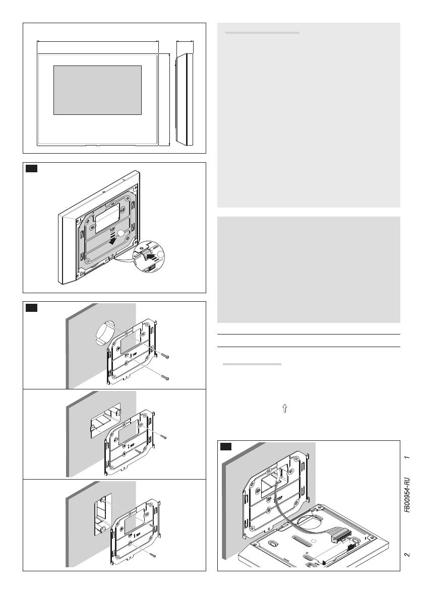
Futura X1 WH
Накладной монтаж
Нажав на пластиковый фиксатор, снимите устройство с метал-
лического кронштейна A. Закрепите металлическую опору к
круглой монтажной коробке Ø 60 мм Ba или к прямоугольной
коробке 503 B B, используя прилагаемые винты и со-
блюдая указание (TOP) . Коробку следует устанавливать на вы-
соте, удобной для пользователя. Избегайте чрезмерного затяги-
вания винтов. Выполнив подключение, установите абонентское
1
D E
F
G
H
I
LOCAL
BUS
LOCAL
BUS
CL.RES
M/S
LOCAL
SW1 SW3
SW4
M1
BUS
CL.RES CL.RES CL.RES
001DC006AC
1 2 3
MASTER SLAVE
M/S M/S
Стр. 3 - Руководство FB00954-RU - вер. 1 - 10/2017 - © CAME S.p.A. - Содержание данного руководства может быть изменено в любое время без предварительного уведомления.
устройство на кронштейн CD. Чтобы отсоединить устройство
от металлического кронштейна, нажмите на пластиковый фик-
сатор и одновременно потяните корпус устройства E.
При встроенной установке обратитесь к руководству из комплек-
та для встроенной установки.
Технические характеристики
Тип
Futura X1 WH
Питание от шины (пост. ток)
15÷20
Потребление (мA макс.)
410
Потребление в дежурном режиме (мА)
<1
Локальный источник питания (пост. ток)
16÷18
Потребление (мA макс.)
370
Потребление отд.светодиода (мА)
(паника, отключение звонка)
1
Температура хранения (°C)
-25 ÷ +70
Рабочая температура (°C)
0 ÷ +35
Класс IP
20
Видеостандарт
PAL/NTSC
Дисплей LCD TFT цветной (дюймы)
7
Опциональные
Клеммная колодка Fa
+Локальный источник питания
BВход линии шины
+Вызов с лестничной площадки
AL Вход сигнала тревоги
Выбор источника питания (BUS/LOCAL) G
Отдельное питание a
Питание от шины
Выбор последнего абонентского устройства на линии (CL.
RES) H
Выбор мастер/подчиненное устройство (M/S) I
В случае вызова, изображение звонящего появляется только на
устройствах, имеющих конфигурацию «МАСТЕР».
Стр. 4 - Руководство FB00954-RU - вер. 1 - 10/2017 - © CAME S.p.A. - Содержание данного руководства может быть изменено в любое время без предварительного уведомления.
Настройка мелодий
Необходимо последовательно выполнить все этапы программирования, описанные ниже:
1. Вход в режим программирования.
Нажмите 5 раз кнопку в течение 5 секунд.
Короткий звуковой сигнал подтвердит вход в режим программирования.
2. Программирование мелодии вызова с вызывной панели.
Для последовательного прослушивания мелодий нажмите кнопку .
Для выбора мелодии и выхода из режима программирования нажмите кнопку .
Для выбора мелодии и продолжения программирования нажмите кнопку .
3. Программирование мелодии дверного звонка.
Для последовательного прослушивания мелодий нажмите кнопку .
Для выбора мелодии и выхода из режима программирования нажмите кнопку .
Для выбора мелодии и продолжения программирования нажмите кнопку .
4. Программирование количества звонков во время вызова.
Нажмите клавишу столько раз, сколько звонков требуется для вызова (от 1 до 6). Спустя 3 секунды после последнего
нажатия клавиши мелодия вызова будет воспроизведена заданное количество раз.
Для выхода из режима программирования нажмите кнопку .
Информация о программировании вызовов приведена в документации к вызывной панели.
  • Page 1 1
  • Page 2 2
  • Page 3 3
  • Page 4 4
  • Page 5 5
  • Page 6 6
  • Page 7 7
  • Page 8 8
  • Page 9 9
  • Page 10 10
  • Page 11 11
  • Page 12 12
  • Page 13 13
  • Page 14 14
  • Page 15 15
  • Page 16 16
  • Page 17 17
  • Page 18 18
  • Page 19 19
  • Page 20 20
  • Page 21 21
  • Page 22 22
  • Page 23 23
  • Page 24 24
  • Page 25 25
  • Page 26 26
  • Page 27 27
  • Page 28 28
  • Page 29 29
  • Page 30 30
  • Page 31 31
  • Page 32 32

CAME FUTURAKITBLACK Инструкция по установке

Тип
Инструкция по установке

CAME FUTURAKITBLACK — это видеодомофон с 7-дюймовым экраном и разрешением 800х512 пикселей, который обеспечивает четкое и детализированное изображение посетителей. Устройство имеет интуитивно понятный интерфейс и простое управление, что позволяет легко принимать вызовы, открывать дверь и просматривать журнал вызовов. CAME FUTURAKITBLACK поддерживает подключение до двух вызывных панелей и двух дополнительных камер, что делает его идеальным решением для многоквартирных домов или частных домов с несколькими входами.

Задайте вопрос, и я найду ответ в документе

Поиск информации в документе стал проще с помощью ИИ

на других языках