Grundfos DW.100.200.AH Installation And Operating Instructions Manual

Тип
Installation And Operating Instructions Manual
DW
Installation and operating instructions
GRUNDFOS INSTRUCTIONS
2
3
Table of contents
DW
English (GB)
Installation and operating instructions. . . . . . . . . . . . . . . . . . . . . . . . . . . . . . . . . 5
Čeština (CZ)
Montážní a provozní návod. . . . . . . . . . . . . . . . . . . . . . . . . . . . . . . . . . . . . . . . 11
Deutsch (DE)
Montage- und Betriebsanleitung . . . . . . . . . . . . . . . . . . . . . . . . . . . . . . . . . . . . 17
Dansk (DK)
Monterings- og driftsinstruktion. . . . . . . . . . . . . . . . . . . . . . . . . . . . . . . . . . . . . 23
Español (ES)
Instrucciones de instalación y funcionamiento . . . . . . . . . . . . . . . . . . . . . . . . . 29
Suomi (FI)
Asennus- ja käyttöohjeet. . . . . . . . . . . . . . . . . . . . . . . . . . . . . . . . . . . . . . . . . . 35
Français (FR)
Notice d'installation et de fonctionnement. . . . . . . . . . . . . . . . . . . . . . . . . . . . . 41
Ελληνικά (GR)
Οδηγίες εγκατάστασης και λειτουργίας . . . . . . . . . . . . . . . . . . . . . . . . . . . . . . . 47
Hrvatski (HR)
Montažne i pogonske upute . . . . . . . . . . . . . . . . . . . . . . . . . . . . . . . . . . . . . . . 53
Magyar (HU)
Telepítési és üzemeltetési utasítás. . . . . . . . . . . . . . . . . . . . . . . . . . . . . . . . . . 59
Italiano (IT)
Istruzioni di installazione e funzionamento . . . . . . . . . . . . . . . . . . . . . . . . . . . . 65
Nederlands (NL)
Installatie- en bedieningsinstructies . . . . . . . . . . . . . . . . . . . . . . . . . . . . . . . . . 71
Polski (PL)
Instrukcja montażu i eksploatacji . . . . . . . . . . . . . . . . . . . . . . . . . . . . . . . . . . . 77
Português (PT)
Instruções de instalação e funcionamento . . . . . . . . . . . . . . . . . . . . . . . . . . . . 83
Srpski (RS)
Uputstvo za instalaciju i rad . . . . . . . . . . . . . . . . . . . . . . . . . . . . . . . . . . . . . . . 89
Русский (RU)
Паспорт, Руководство по монтажу и эксплуатации . . . . . . . . . . . . . . . . . . . 95
Svenska (SE)
Monterings- och driftsinstruktion . . . . . . . . . . . . . . . . . . . . . . . . . . . . . . . . . . . 102
Slovensko (SI)
Navodila za montažo in obratovanje. . . . . . . . . . . . . . . . . . . . . . . . . . . . . . . . 108
Table of contents
4
DW
Slovenčina (SK)
Návod na montáž a prevádzku . . . . . . . . . . . . . . . . . . . . . . . . . . . . . . . . . . . . 114
Appendix. . . . . . . . . . . . . . . . . . . . . . . . . . . . . . . . . . . . . . . . . . . . . . . . . . . . . 120
Declaration of conformity . . . . . . . . . . . . . . . . . . . . . . . . . . . . . . . . . . . . . . . . 129
Declaration of conformity EAC . . . . . . . . . . . . . . . . . . . . . . . . . . . . . . . . . . . . 131
English (GB)
5
English (GB) Installation and operating instructions
Original installation and operating instructions
CONTENTS
Page
1. Symbols used in this document
2. General description
2.1 Applications
Grundfos DW pumps are designed for pumping:
water from construction sites,
water in mining industry,
groundwater,
surface water.
The DW pumps can handle all solids that can pass
through the suction strainer.
The compact design makes the pumps suitable for
both temporary and permanent installation. As the
pumps are made of light materials such as
composite and aluminium, they are easy to move
from one place to another.
2.2 Operating conditions
2.2.1 pH-value
The DW pumps can cope with pH-values ranging
from 5 to 8.
2.2.2 Liquid temperature
Liquid temperature: 0 °C to +40 °C.
2.2.3 Density of pumped liquid
Maximum density of pumped liquid: 1100 kg/m
3
.
1. Symbols used in this document
5
2. General description
5
2.1 Applications
5
2.2 Operating conditions
5
2.3 Sound pressure level
6
3. Safety
6
4. Transportation and storage
6
5. Installation
6
6. Electrical connection
7
6.1 Motor protection
7
6.2 Frequency converter operation
7
7. Startup
8
7.1 Direction of rotation
8
8. Maintenance and service
8
8.1 Contaminated pumps
9
9. Fault finding
1
0
10. Disposal
1
0
Warning
Prior to installation, read these installation
and operating instructions. Installation and
operation must comply with local
regulations and accepted codes of good
practice.
Warning
The use of this product requires
experience with and knowledge of the
product.
Persons with reduced physical, sensory or
mental capabilities must not use this
product, unless they are under supervision
or have been instructed in the use of the
product by a person responsible for their
safety.
Children must not use or play with this
product.
Warning
If these safety instructions are not
observed, it may result in personal injury.
Warning
If these instructions are not observed, it
may lead to electric shock with consequent
risk of serious personal injury or death.
Caution
If these safety instructions are not
observed, it may result in malfunction or
damage to the equipment.
Note
Notes or instructions that make the job
easier and ensure safe operation.
Warning
Depending on the temperature of the
pumped liquid, the surface of the pump
may be so hot or cold that it may cause
burns or personal injury.
English (GB)
6
2.2.4 Installation depths
2.2.5 Level of pumped liquid
The lowest stop level is the level where the pump
starts to suck air.
The A models have an integrated level control
system. A stands for "Automatic". This system will
stop the pump when the stop level is reached. Model
DW.50.08.A has an external float switch.
2.2.6 Operation
The pumps are designed for continuous operation.
The A models have to be switched over to "C" for
continuous operation.
For model DW.50.08.A, the float switch must be tied
up. See fig. 1.
Fig. 1 DW.50.08.A
2.3 Sound pressure level
The sound pressure level of the pump is lower than
the limiting values stated in the EC Council Directive
2006/42//EC relating to machinery.
3. Safety
4. Transportation and storage
The pump may be transported and stored in a
vertical or horizontal position. Make sure that it
cannot roll or fall over.
Always lift the pump by its carrying handle, never by
the motor cable or the hose/pipe.
If the staff do not have the necessary knowledge
about handling and lifting the pump they must be
trained and instructed accordingly.
For long periods of storage, the pump must be
protected against moisture and heat.
After a long period of storage, the pump should be
inspected before it is put into operation. Make sure
that the impeller can rotate freely. Pay special
attention to the shaft seals and the cable entry.
5. Installation
Installation dimensions, see page 120.
Prior to installation, check the oil level in the oil
chamber, see section 8. Maintenance and service.
The DW pumps have pump housing for free-standing
installation.
The pump can be installed with a hose/pipe.
In order to facilitate service of the pump, fit a flexible
union or coupling to the discharge line for easy
separation.
If a hose is used, make sure that the hose does not
buckle and that the inside diameter of the hose
matches that of the discharge port.
If the pump is installed in muddy conditions or on
uneven ground, it is recommended to support the
pump on bricks.
Lower the pump into the liquid.
Pump type Maximum depth
DW.50.08.(A)1/3 5 metres
DW.50.07.(A)1
DW.50.09.(A)3
DW.65.27.(A)
DW.65.39.(A)H
DW.100.66.(A)H
DW.100.39.(A)
DW.100.66.(A)
DW.100.110.(A)H
DW.100.200.(A)H
DW.150.110.(A)
DW.150.200.(A)
17 metres
TM01 4948 1199
Warning
Pump installation in wells must be carried
out by specially trained persons.
English (GB)
7
Model A:
The A models have an integrated level control
system.
By means of two electrodes, the level control system
measures the water level in the water level
compartment. The short electrode starts the pump
and the long one stops the pump.
When the pump has drained the pit/sump, the rubber
valve, situated next to the electrodes on top of the
motor housing, will draw in air to drain the pump.
When the A models are used for automatic operation
in deep pits/sumps, a non-return valve must be
mounted immediately after the discharge port to
prevent backflow and thus intermittent operation
when the pit/sump has been drained. See fig. 2.
Fig. 2 Model A
6. Electrical connection
The electrical connection of the pump should be
carried out in accordance with local regulations.
The operating voltage and frequency are marked on
the nameplate. Voltage tolerance: ± 10 % of the
voltage stated on the nameplate. Make sure that the
motor is suitable for the electricity supply available at
the installation site.
6.1 Motor protection
All Grundfos DW pumps have a thermal switch built
into the stator windings.
All single-phase Grundfos DW pumps are supplied
with an operating capacitor.
For capacitor sizes, see the table below:
6.2 Frequency converter operation
The DW pumps with integrated motor starter should
not be connected to a frequency converter, as this
may result in damage to the motor.
Frequency converter operation will often expose the
motor insulation system to a heavier load and cause
the motor to be more noisy than usual due to eddy
currents caused by voltage peaks.
In addition, large motors driven via a frequency
converter will be loaded by bearing currents.
TM01 3433 3998
Warning
Connect the pump to an external mains
switch placed close to the pump and to a
motor-protective circuit breaker.
Make sure you can lock the mains switch
in OFF position (isolated). Type and
requirements as specified in EN 60204-1,
5.3.2.
Pump type
Operating capacitor
[μF]
DW.50.07.1 16
DW.50.08.1 16
English (GB)
8
7. Startup
When the electrical connection has been carried out,
the pump is ready for operation.
Submerge the pump into the liquid to be pumped and
start it.
The valve for the level control system will
automatically vent the pump. Therefore, there will be
no problems with air in the pump.
7.1 Direction of rotation
All single-phase pumps are factory-set to the
correct direction of rotation.
Before starting up three-phase pumps, check the
direction of rotation. The direction of rotation should
be clockwise.
When starting up, the pump will jerk in the opposite
direction to the direction of rotation (the arrow on the
top cover indicates the direction of the jerk). If the
direction of rotation is wrong, interchange two of the
three phases of the electricity supply.
8. Maintenance and service
Before carrying out maintenance and service, make
sure that the pump has been thoroughly flushed with
clean water. Rinse the pump parts in water after
dismantling.
Pumps running normal operation should be
inspected at least once a year. If the pumped liquid is
very muddy or sandy, inspect the pump at shorter
intervals.
When the pump is new or after replacement of the
shaft seals, check the oil level after one week of
operation.
For long and trouble-free operation of the pump the
following points should be checked regularly:
Power consumption
Oil level and oil condition
The oil becomes greyish white like milk if it
contains water. This may be the result of a
defective shaft seal. The oil should be replaced
after 3000 hours of operation (DW.50.08, 1000
hours).
Use Shell Ondina X420.
Note: Used oil must be disposed of in
accordance with local regulations.
The following table states how much oil the DW
pumps must have in the oil chamber:
* Filled with grease (Klüber Synteso Proba 330).
Warning
Before starting work on the pump, make
sure that the electricity supply has been
switched off and that it cannot be
accidentally switched on. Furthermore,
all rotating parts must have stopped
moving.
Warning
When unscrewing the inspection screw of
the oil chamber, please note that
pressure may have built up in the
chamber. Do not remove the screw until
the pressure has been fully relieved.
Pump type Voltage
Quantity of oil
[l]
Single-phase
DW.50.07.1 1 x 230 V 0.25
DW.50.07.A1 1 x 230 V 0.25
DW.50.08.1 1 x 230 V *
DW.50.08.A1 1 x 230 V *
Three-phase
DW.50.08.3 3 x 400 V *
DW.50.08.A3 3 x 400 V *
DW.50.09.3 3 x 400 V 0.25
DW.50.09.A3 3 x 400 V 0.25
DW.65.27 3 x 400 V 0.3
DW.65.27.A 3 x 400 V 0.3
DW.65.39 3 x 400 V 0.3
DW.65.39.A 3 x 400 V 0.3
DW.100.66.H 3 x 400 V 0.3
DW.100.66.AH 3 x 400 V 0.3
DW.100.39 3 x 400 V 0.3
DW.100.39.A 3 x 400 V 0.3
DW.100.66 3 x 400 V 0.3
DW.100.66.A 3 x 400 V 0.3
DW.100.110.H 3 x 400 V 2.3
DW.100.110.AH 3 x 400 V 2.3
DW.150.110 3 x 400 V 2.3
DW.150.110.A 3 x 400 V 2.3
DW.100.200.H 3 x 400 V 2.3
DW.100.200.AH 3 x 400 V 2.3
DW.150.200 3 x 400 V 2.3
DW.150.200.A 3 x 400 V 2.3
English (GB)
9
Cable entry
Make sure that the cable entry is watertight and
that the cables are not bent sharply and/or
pinched.
Pump parts
Check the impeller, pump housing, diffuser,
impeller disc etc. for possible wear. Replace
defective parts.
Ball bearings
Check the shaft for noisy or heavy operation (turn
the shaft by hand). Replace defective ball
bearings.
A general overhaul of the pump is usually
required in case of defective ball bearings or poor
motor function. This work must be carried out by
the manufacturer or a competent workshop.
8.1 Contaminated pumps
If Grundfos is requested to service the pump,
Grundfos must be contacted with details about the
pumped liquid, etc. before the pump is returned for
service. Otherwise Grundfos can refuse to accept
the pump for service.
Possible costs of returning the pump are paid by the
customer.
However, any application for service (no matter to
whom it may be made) must include details about
the pumped liquid if the pump has been used for
liquids which are injurious to health or toxic.
Note
If a pump has been used for a liquid which
is injurious to health or toxic, the pump will
be classified as contaminated.
English (GB)
10
9. Fault finding
10. Disposal
This product or parts of it must be disposed of in an
environmentally sound way:
1. Use the public or private waste collection service.
2. If this is not possible, contact the nearest
Grundfos company or service workshop.
Subject to alterations.
Warning
Make sure that all power supplies have
been switched off and that all rotating
parts have stopped moving before
attempting to diagnose any fault.
Fault Cause Remedy
1. Motor does not start. Fuses
blow or motor starter trips
immediately. Caution: Do not
start again!
a) Supply failure; short-circuit;
earth-leakage fault in cable or
motor winding.
Have the cable and motor checked
and repaired by a qualified
electrician.
b) Fuses blow due to use of
wrong type of fuse.
Install fuses of the correct type.
c) Impeller blocked by impurities. Clean the impeller.
d) The electrodes are dirty or
defective.
Clean or replace the electrodes.
2. Pump operates, but motor
starter trips after a short while.
a) Low setting of thermal relay in
motor starter.
Set the relay in accordance with
the specifications on the
nameplate.
b) Increased current
consumption due to large
voltage drop.
Measure the voltage between
motor phases. Tolerance: ± 10 %.
c) Impeller blocked by impurities.
Increased current
consumption in all three
phases.
Clean the impeller.
d) For pumps running automatic
operation, the non-return
valve may be defective.
Replace the non-return valve
3. Pump operates at
below-standard performance
and power consumption.
a) Impeller blocked by impurities. Clean the impeller.
Check the direction of rotation and
possibly interchange two phases,
see section 7.1 Direction of
rotation.
b) Wrong direction of rotation.
c) The electrodes are dirty or
defective.
Clean or replace the electrodes.
4. Pump operates, but gives no
liquid.
a) The electrodes are dirty or
defective.
Clean or replace the electrodes.
Čeština (CZ)
11
Čeština (CZ) Montážní a provozní návod
Překlad originální anglické verze
OBSAH
Strana
1. Symboly použité v tomto návodu
2. Všeobecný popis
2.1 Použití
Čerpadla Grundfos DW jsou určena pro čerpání:
vody na staveništích,
vody v těžebním průmyslu,
spodní vody,
povrchové vody.
Čerpadla DW mohou čerpat vodu obsahující pevné
mechanické nečistoty, které projdou vtokovým sítem
čerpadla.
Kompaktní konstrukce těchto čerpadel umožňuje
jejich mobilní, stejně jako stacionární použití.
Vzhledem k tomu, že tato čerpadla jsou vyrobena
z lehkých materiálů, jako je kompozit a hliník, lze je
snadno přepravovat z jednoho stanoviště na druhé.
2.2 Provozní podmínky
2.2.1 Hodnota pH
Čerpadla DW jsou vhodná pro čerpání médií, která
vykazují hodnotu pH 5 až pH 8.
2.2.2 Teplota čerpané kapaliny
Teplota čerpané kapaliny: 0 °C až +40 °C.
2.2.3 Hustota čerpané kapaliny
Maximální přípustná hustota čerpané kapaliny:
1100 kg/m
3
.
1. Symboly použité v tomto návodu
11
2. Všeobecný popis
11
2.1 Použití
11
2.2 Provozní podmínky
11
2.3 Provozní hlučnost
12
3. Safety
12
4. Přeprava a skladování
12
5. Instalace
12
6. Elektrické připojení
13
6.1 Jištění motoru
13
6.2 Provoz s frekvenčním měničem
13
7. Uvedení do provozu
14
7.1 Kontrola směru otáčení
14
8. Údržba a servis
14
8.1 Kontaminovaná čerpadla
15
9. Přehled poruch
16
10. Likvidace výrobku
16
Varování
Před zahájením montážních prací si
pečlivě přečtěte tyto montážní a provozní
předpisy. Montáž a provoz provádějte
rovněž v souladu s místními předpisy a se
zavedenou osvědčenou praxí.
Varování
Použití tohoto výrobku vyžaduje
zkušenosti a znalosti výrobku.
Osobám s omezenou fyzickou nebo
duševní způsobilostí je zakázáno používat
výrobek, výjimkou může být tato osoba,
která je pod dohledem osoby zodpovědné
za bezpečnost a byla řádně vyškolená na
obsluhu tohoto výrobku.
Děti nesmí obsluhovat, ani hrát si s tímto
výrobkem.
Varování
Bezpečnostní pokyny uvedené v tomto
montážním a provozním návodu, jejichž
nedodržení může způsobit ohrožení osob.
Varování
Pokud nebudou tyto bezpečnostní pokyny
dodrženy, mohlo by dojít k úrazu
elektrickým proudem s následným rizikem
vážné újmy na zdraví nebo smrti osob.
Pozor
Pokud nebudou tyto bezpečnostní pokyny
dodrženy, mohlo by dojít k poruše nebo
poškození zařízení.
Pokyn
Doporučení nebo pokyny, které mají
usnadnit práci a zajišťovat bezpeč
provoz.
Varování
V závislosti na teplotě čerpané kapaliny
může být povrch čerpadla tak horký nebo
chladný, že může způsobit popáleniny
nebo vážnou újmu na zdraví osob.
Čeština (CZ)
12
2.2.4 Hloubky ponoření
2.2.5 Úroveň hladiny čerpané kapaliny
Nejnižší vypínací úroveň hladiny čerpané kapaliny je
úroveň, než čerpadlo začne nasávat vzduch.
Modely A jsou vybaveny integrovaným systémem
kontroly hladiny. Písmeno A znamená "automatické
vypínání". Tento systém odstaví při dosažení
vypínací hladiny čerpadlo z provozu.
Model DW.50.08.A má externí plovákový spínač.
2.2.6 Provozní režim
Čerpadla jsou zkonstruována pro trvalý provoz.
Modely A je nutno pro trvalý provoz přepnout do
polohy "C".
U modelu čerpadla DW 50.08.A je třeba provést pro
trvalý provoz uchycení plovákového spínače.
Viz obr. 1.
Obr. 1 DW.50.08.A
2.3 Provozní hlučnost
Hodnota provozní hlučnosti je u čerpadel DW nižší
než kolik činí mezní hodnoty požadované směrnicí
Rady EU 2006/42/ES pro strojní zařízení.
3. Safety
4. Přeprava a skladování
Čerpadlo je možno přepravovat a skladovat jak ve
svislé, tak i ve vodorovné poloze. Čerpadlo zajistěte
tak, aby se v průběhu přepravy a skladování
nemohlo převalovat a aby bylo vyloučeno nebezpečí
jeho pádu z výšky.
Při zvedání držte čerpadlo vždy za rukojet, nikdy ne
za přívodní elektrický kabel nebo za výtlačnou
hadici, popř. trubku.
Pokud personál nemá potřebné znalosti
o manipulací a zdvihání čerpadla, musí být
odpovídajícím způsobem vyškolen a instruován.
Při delším skladování chraňte čerpadlo proti vlhkosti
a nadměrnému teplu.
Jestliže bylo čerpadlo delší dobu mimo provoz,
je třeba je před novým uvedením do provozu
zkontrolovat. Otáčením oběžného kola rukou
prověřte, zda jde rotor čerpadla volně protáčet.
Při kontrole se zaměřte zejména na stav hřídelových
ucpávek a kabelové průchodky.
5. Instalace
Rozměry čerpadel jsou uvedeny na straně 120.
Před zahájením instalace zkontrolujte stav oleje
v olejové komoře, viz odd. 8. Údržba a servis.
Těleso čerpadel DW je navrženo tak, aby instalace
do pracovní polohy znamenala pouze postavení
čerpadla (viz. obr. 2).
Čerpadla lze instalovat s použitím výtlačné hadice
nebo trubky.
K usnadnění demontáže pro účel servisu a údržby
čerpadla je žádoucí umístit do výtlačného potrubí
spojovací šroubení nebo rychlospojku.
Pokud použijete výtlačnou hadici, zajistěte, aby u ní
nedocházelo ke zlomům a aby světlost této hadice
odpovídala světlosti výtlačného hrdla čerpadla.
Jestliže má být čerpadlo instalováno na bahnitém
nebo nerovném terénu, doporučujeme je podložit
cihlami nebo podobným materiálem.
Čerpadlo ponořte do čerpané kapaliny.
Typ čerpadla Max. hloubka ponoření
DW.50.08.(A)1/3 5 metrů
DW.50.07.(A)1
DW.50.09.(A)3
DW.65.27.(A)
DW.65.39.(A)H
DW.100.66.(A)H
DW.100.39.(A)
DW.100.66.(A)
DW.100.110.(A)H
DW.100.200.(A)H
DW.150.110.(A)
DW.150.200.(A)
17 metrů
TM01 4948 1199
Varování
Pump installation in wells must be carried
out by specially trained persons.
Čeština (CZ)
13
Model A:
Modely čerpadel A mají vestavěn systém hlídání
hladiny.
Pomocí dvou elektrod měří tento řídící systém stav
vodní hladiny v sacím prostoru čerpadla.
Krátká elektroda čerpadlo zapíná a dlouhá elektroda
je zase vypíná.
Jakmile je obsah studny, popř. šachty vyčerpán,
začne pryžový ventil umístěný na horní straně tělesa
motoru nasávat vzduch. Tím dojde k úplnému
vyprázdněčerpadla.
V případě, že se model čerpadel A použije pro
automatický provoz v hlubokých studních nebo
šachtách, musí být bezprostředně za výtlačným
hrdlem čerpadla umístěn zpětný ventil, který bude po
vyčerpání studny či šachty zabraňovat zpětnému
proudění vody a tím i přerušovanému provozu
čerpadla. Viz obr. 2.
Obr. 2 Model A
6. Elektrické připojení
Elektrické připojení čerpadla musí být provedeno
v souladu s platnými normami a místními předpisy.
Napájecí napětí a kmitočet jsou uvedeny na typovém
štítku čerpadla. Napětová tolerance: ± 10 %
jmenovitého napětí uvedeného na typovém štítku.
Dbejte, aby údaje uvedené na typovém štítku
odpovídaly parametrům dané rozvodné sítě, v níž
má být čerpadlo provozováno.
6.1 Jištění motoru
Všechna čerpadla Grundfos DW mají zabudovan
termospínač ve statorovém vinutí motoru.
Všechna čerpadla Grundfos DW poháně
jednofázovým motorem jsou vybavena provozním
kondenzátorem.
Velikosti kondenzátorů uvádí následující tabulka:
6.2 Provoz s frekvenčním měničem
Čerpadla DW s integrovanou motorovou ochranou
nesmí být připojena na frekvenční měnič, protože by
mohlo dojít k poškození motoru.
Připojení na frekvenční měnič bude mít často za
následek větší zátěž izolace motoru a motor bude
vykazovat větší provozní hlučnost oproti normálnímu
provozu působením zpětných proudů způsobenými
napěťovými špičkami.
Kromě toho budou velké motory poháně
frekvenčním měničem zatíženy ložiskovými proudy.
TM01 3433 3998
Varování
Čerpadlo musí být připojeno k externímu
ťovém vypínači umístěnému v blízkosti
čerpadla a k ochrannému jističi motoru.
Zajistěte, aby bylo možno uzamknout
ťový vypínač v poloze VYP (odpojeno).
Typ a požadavky dle specifikace normy EN
60204-1, 5,3,2.
Typ čerpadla
Provozní kondenzátor
[μF]
DW.50.07.1 16
DW.50.08.1 16
Čeština (CZ)
14
7. Uvedení do provozu
Po provedení elektrického připojení je čerpadlo
připraveno k provozu.
Čerpadlo ponořte do čerpané kapaliny a uveďte do
provozu.
Ventil řídícího hladinového systému zajistí
automatické odvzdušněčerpadla.
Vzduch v čerpadle proto nepředstavuje žádný
problém.
7.1 Kontrola směru otáčení
Všechna čerpadla Grundfos DW poháně
jednofázovým motorem jsou ve výrobním závodě
zapojena tak, aby u nich byl zajištěn správný směr
otáčení.
U čerpadel s trojfázovým motorem proveďte před
jejich uvedením do provozu kontrolu směru otáčení.
Hřídel čerpadla se musí otáčet ve směru pohybu
hodinových ručiček.
Při zapnutí čerpadla je na hřídeli patrný pohyb
(škubnutí) proti směru otáčení (viz šipku na horním
krytu čerpadla). V případě nesprávného směru
otáčení hřídele čerpadla proveďte přepojení dvou
fázových vodičů sítové přípojky.
8. Údržba a servis
Před započetím údržbářských a servisních prací
vypláchněte čerpadlo pečlivě čistou vodou.
Demontované součásti čerpadla očistěte
a opláchněte rovněž čistou vodou.
Při normálním provozu je žádoucí provádět kontrolu
čerpadla minimálně jedenkrát ročně.
Jestliže čerpaná kapalina obsahuje příměsi kalu či
písku, provádějte kontrolu čerpadla v kratších
časových odstupech.
U nového čerpadla, popř. u čerpadla, u něhož byla
provedena výměna ucpávek, proveďte kontrolu oleje
po jednom týdnu provozu.
K zajištění dlouhodobého a bezporuchového
provozu provádějte pravidelnou kontrolu:
Energetického příkonu
Stavu a kvality oleje
Olej s obsahem vody má šedou barvu a mléčnou
konzistenci. Z toho se dá usuzovat na
poškozenou ucpávku. Po 3000 provozních
hodinách proveďte výměnu oleje (DW.50.08,
1000 hodinách).
Používejte olej Ondina X420 Shell.
Pozor: Použitý olej zlikvidujte v souladu
spříslušnými předpisy!
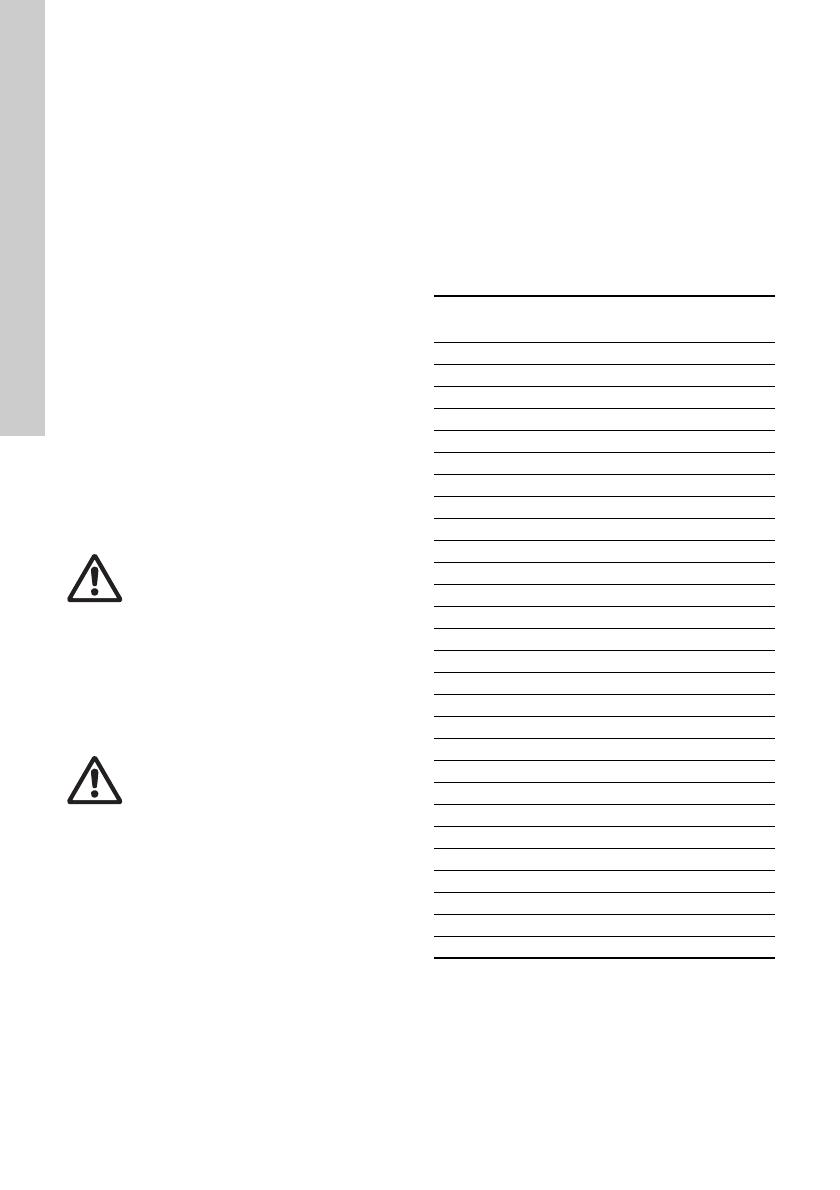
Olejové komory čerpadel DW musí obsahovat
následující množství oleje:
* S tukovou náplní (Klüber Synteso Proba 330).
Varování
Před zahájením práce na čerpadle
bezpodmínečně vypněte přívod
elektrického napájecího napě
asoučasně jej zajistěte proti náhodnému
zapnutí. Otočné součásti čerpadla musí
být v klidu.
Varování
Při uvolňování kontrolní šroubové zátky
olejové komory mějte na paměti, že tato
komora může být pod tlakem. Šroubovou
zátku v žádném případě zcela
nevyjímejte a vyčkejte, až se tlak
vyrovná.
Typ čerpadla Napě
Množství oleje
[l]
Čerpadla s jednofázovým motorem
DW.50.07.1 1 x 230 V 0,25
DW.50.07.A1 1 x 230 V 0,25
DW.50.08.1 1 x 230 V *
DW.50.08.A1 1 x 230 V *
Čerpadla s trojfázovým motorem
DW.50.08.3 3 x 400 V *
DW.50.08.A3 3 x 400 V *
DW.50.09.3 3 x 400 V 0,25
DW.50.09.A3 3 x 400 V 0,25
DW.65.27 3 x 400 V 0,3
DW.65.27.A 3 x 400 V 0,3
DW.65.39 3 x 400 V 0,3
DW.65.39.A 3 x 400 V 0,3
DW.100.66.H 3 x 400 V 0,3
DW.100.66.AH 3 x 400 V 0,3
DW.100.39 3 x 400 V 0,3
DW.100.39.A 3 x 400 V 0,3
DW.100.66 3 x 400 V 0,3
DW.100.66.A 3 x 400 V 0,3
DW.100.110.H 3 x 400 V 2,3
DW.100.110.AH 3 x 400 V 2,3
DW.150.110 3 x 400 V 2,3
DW.150.110.A 3 x 400 V 2,3
DW.100.200.H 3 x 400 V 2,3
DW.100.200.AH 3 x 400 V 2,3
DW.150.200 3 x 400 V 2,3
DW.150.200.A 3 x 400 V 2,3
Čeština (CZ)
15
Kabelové průchodky
Dbejte na to, aby kabelová průchodka byla vždy
vodotěsná a aby nedošlo ke zlomu kabelů nebo
k jejich poškození.
Komponentů čerpadla
U oběžného kola, tělesa čerpadla, rozváděcího
ústrojí a příložné desky oběžného kola
kontrolujte stupeň opotřebení. Poškozené
součásti vyměňte.
Kuličkových ložisek
U hřídele čerpadla proveďte kontrolu, zda se
nezvyšuje provozní hlučnost. Protáčejte rukou
oběžným kolem a zkontrolujte, zda při protáčení
nevzniká hluk a zda se hřídel otáčí volně bez
zvýšeného odporu. Vadná kuličková ložiska
vyměňte.
V případě, že se objeví závada na kuličkových
ložiskách nebo na motoru, je za normálních
okolností nutno provést celkovou kontrolu
čerpadla. Práce spojené s touto kontrolou
provede nejlépe výrobce nebo oprávně
servisní dílna.
8.1 Kontaminovaná čerpadla
Při eventuálním uplatnění požadavku na provedení
servisních prací na kontaminovaném čerpadle u fy
Grundfos předejte spolu s objednávkou před
odesláním čerpadla podrobné informace o čerpané
kapalině. Jinak může Grundfos převzetí čerpadla
odmítnout.
Případné náklady spojené s vrácením čerpadla jdou
k tíži odesilatele.
Informace o čerpané kapalině by však měly být
přiloženy ke každé objednávce servisních prací na
čerpadle, které čerpalo zdraví škodlivé nebo
jedovaté kapaliny, bez ohledu na to, kdo bude tyto
práce provádět.
Pokyn
Pokud bylo čerpadlo používáno k čerpání
zdraví škodlivé nebo jedovaté kapaliny,
považuje se za kontaminované.
Čeština (CZ)
16
9. Přehled poruch
10. Likvidace výrobku
Tento výrobek nebo jeho části musí být po skončení
doby jeho životnosti ekologicky zlikvidovány:
1. Využijte služeb místní veřejné či soukromé
organizace, zabývající se sběrem a zpracováním
odpadů.
2. Pokud taková organizace ve vaší lokalitě
neexistuje, kontaktujte nejbližší pobočku
Grundfos nebo servisní středisko.
Technické změny vyhrazeny.
Varování
Před zahájením vyhledávání příčiny
poruchy bezpodmínečně vypněte přívod
elektrického napájecího napětí. Otoč
součásti čerpadla musí být v klidu.
Porucha Příčina Odstraně
1. Motor se po zapnutí
nerozeběhne. Pojistky se
přepalují nebo motorová
ochrana vypíná.
Pozor: Znovu nezapínejte!
a) Přerušený přívod napájení.
Zkrat v kabelu nebo ve vinutí
motoru.
Nechte provést kontrolu příp.
opravu servisem.
b) Použité jištění je nesprávného
typu.
Opravte jištění.
c) Oběžné kolo je zablokováno
nečistotami.
Vyčistěte oběžné kolo.
d) Zanesené nebo poškoze
elektrody.
Vyčistěte, příp. vyměňte elektrody.
2. Čerpadlo pracuje, ale
motorová ochrana je po krátké
době vypíná.
a) Nadproudové relé motorové
ochrany je nastaveno na příliš
nízkou vypínací hodnotu.
Opravte nastavení dle parametrů
na typovém štítku
čerpadla.
b) Zvýšený příkon motoru
vdůsledku většího úbytku
napětí.
Změřte napětí mezi dvěma fázemi.
Tolerance: ± 10 %.
c) Oběžné kolo blokováno
nečistotami. Zvýšený příkon
motoru ve všech fázích.
Vyčistěte oběžné kolo.
d) U čerpadel pracujících
v automatickém provozu může
být příčinou vadný zpětný
ventil.
Vyměňte zpětný ventil.
3. Čerpadlo pracuje s nižším
výkonem a s velmi nízkým
příkonem.
a) Oběžné kolo ucpáno
nečistotami.
Vyčistěte oběžné kolo.
b) Nesprávný směr otáčení. Zkontrolujte směr otáčení a příp.
jej změňte přepojením dvou
fázových vodičů. Viz 7.1 Kontrola
směru otáčení
.
c) Zanesené nebo vadné
elektrody.
Vyčistěte, příp. vyměňte elektrody.
4. Čerpadlo pracuje, nečerpá
však vodu.
a) Znečistěné nebo vadné
elektrody.
Vyčistěte, příp. vyměňte elektrody.
Deutsch (DE)
17
Deutsch (DE) Montage- und Betriebsanleitung
Übersetzung des englischen Originaldokuments
INHALTSVERZEICHNIS
Seite
1. Verwendete Symbole
2. Allgemeine Beschreibung
2.1 Verwendungszweck
Grundfos DW Pumpen eignen sich zur Förderung
von:
Wasser auf Baustellen,
Wasser in der Minenindustrie,
Grundwasser,
Oberflächenwasser.
Die DW Pumpen können Wasser mit festen Bestand-
teilen fördern, die das Einlaufsieb passieren können.
Durch die kompakte Bauweise sind die Pumpen
sowohl für den transportablen Einsatz als auch für
die stationäre Installation geeignet. Da die Pumpen
aus leichten Werkstoffen, sowie Composit und Alu-
minium, hergestellt sind, lassen sich die Pumpen
leicht von einem Einsatzort zum anderen transportie-
ren.
2.2 Betriebsbedingungen
2.2.1 pH-Wert
Die DW Pumpen eignen sich zur Förderung von
Medien mit einem pH-Wert zwischen 5 und 8.
2.2.2 Medientemperatur
Medientemperatur: 0 °C bis +40 °C.
2.2.3 Dichte des Fördermediums
Maximal zulässige Dichte des Fördermediums:
1100 kg/m
3
.
1. Verwendete Symbole
17
2. Allgemeine Beschreibung
17
2.1 Verwendungszweck
17
2.2 Betriebsbedingungen
17
2.3 Schalldruckpegel
18
3. Safety
18
4. Transport und Lagerung
18
5. Montage
18
6. Elektrischer Anschluss
19
6.1 Motorschutz
19
6.2 Frequenzumrichterbetrieb
19
7. Inbetriebnahme
20
7.1 Kontrolle der Drehrichtung
20
8. Instandhaltung und Wartung
20
8.1 Verunreinigte Pumpen
21
9. Störungsübersicht
22
10. Entsorgung
22
Warnung
Lesen Sie diese Montage- und Betriebsan-
leitung vor der Montage. Montage und
Betrieb müssen nach den örtlichen Vor-
schriften und den anerkannten Regeln der
Technik erfolgen.
Warnung
Die Benutzung dieses Produktes erfordert
Erfahrung und Wissen über das Produkt.
Personen, die in ihren körperlichen, geisti-
gen oder sensorischen Fähigkeiten einge-
schränkt sind, dürfen dieses Produkt nur
benutzen, wenn sie unter Aufsicht sind,
oder wenn sie von einer für ihre Sicherheit
verantwortlichen Person im Gebrauch des
Produktes unterwiesen worden sind.
Kinder dürfen dieses Produkt nicht benut-
zen oder damit spielen.
Warnung
Die Nichtbeachtung dieser Sicherheitshin-
weise kann zu Personenschäden führen.
Warnung
Ein Nichtbeachten dieser Hinweise kann
zu einem elektrischen Schlag führen, der
schwere Personenschäden oder den Tod
zur Folge haben kann.
Achtung
Die Nichtbeachtung dieser Sicherheitshin-
weise kann Fehlfunktionen oder Sach-
schäden zur Folge haben.
Hinweis
Hinweise oder Anweisungen, die die Arbeit
erleichtern und einen sicheren Betrieb
gewährleisten.
Warnung
Je nach Temperatur des Fördermediums
kann die Oberfläche der Pumpe so heiß
oder kalt werden, dass sie Verbrennungen
oder Personenschäden verursacht.
Deutsch (DE)
18
2.2.4 Eintauchtiefen
2.2.5 Niveau des Fördermediums
Das niedrigste Ausschaltniveau ist das Niveau, bei
dem die Pumpe Luft ansaugt.
Die A-Modelle haben ein integriertes Niveaukontroll-
system. A bedeutet "Automatisch". Dieses System
schaltet die Pumpe aus, wenn das Ausschaltniveau
erreicht wird.
Modell DW.50.08.A hat einen externen Schwimmer-
schalter.
2.2.6 Betriebsart
Die Pumpen sind für Dauerbetrieb ausgelegt.
Die A-Modelle müssen auf "C" umgeschaltet werden,
um im Dauerbetrieb zu laufen.
Bei Modell DW.50.08.A muss der Schwimmerschal-
ter befestigt werden, siehe Abb. 1.
Abb. 1 DW.50.08.A
2.3 Schalldruckpegel
Der Schalldruckpegel der Pumpe liegt unter den
Grenzwerten, die in der EG-Richtlinie 2006/42/EG
für Maschinen angeführt sind.
3. Safety
4. Transport und Lagerung
Die Pumpe lässt sich sowohl in senkrechter als auch
waagerechter Stellung transportieren.
Wenn die Mitarbeiter nicht über die erforderlichen
Kenntnisse in Bezug auf das Handhaben und Heben
der Pumpe verfügen, müssen sie entsprechend
geschult und instruiert werden.
Bei längerer Lagerung ist die Pumpe gegen Feuch-
tigkeit, Wärme und Frost zu schützen.
Nach längerem Stillstand ist die Pumpe zu überprü-
fen, bevor sie in Betrieb gesetzt wird. Freigängigkeit
durch Drehen des Laufrades von Hand überprüfen.
Besonders auf die Wellenabdichtungen und die
Kabeleinführungen achten.
5. Montage
Einbaumaße, siehe Seite 120.
Vor der Montage den Ölstand in der Ölkammer prü-
fen, siehe Abschnitt 8. Instandhaltung und Wartung.
Die DW Pumpen haben ein Pumpengehäuse für frei-
stehende Montage.
Die Pumpen lassen sich mit Schlauch oder Rohr ein-
bauen.
Um die Wartung der Pumpe zu erleichtern, sollte an
der Druckleitung eine Verschraubung oder eine flexi-
ble Kupplung montiert werden.
Wird ein Schlauch verwendet, ist sicherzustellen,
dass dieser keine Knickstellen aufweist und dass der
Innenquerschnitt dem Pumpen-Druckstutzen ange-
passt ist.
Erfolgt die Montage auf einer schlammigen oder
unebenen Oberfläche, empfiehlt es sich, die Pumpe
mit Ziegelsteinen o.ä. abzustützen.
Die Pumpe in das Fördermedium eintauchen.
Pumpentyp Max. Tiefe
DW.50.08.(A)1/3 5 m
DW.50.07.(A)1
DW.50.09.(A)3
DW.65.27.(A)
DW.65.39.(A)H
DW.100.66.(A)H
DW.100.39.(A)
DW.100.66.(A)
DW.100.110.(A)H
DW.100.200.(A)H
DW.150.110.(A)
DW.150.200.(A)
17 m
TM01 4948 1199
Warnung
Pump installation in wells must be carried
out by specially trained persons.
Sicherstellen, dass sie nicht rollen oder
umkippen kann.
Die Pumpe immer am Handgriff, nie am
Motorkabel oder am Schlauch bzw. Rohr
heben.
Hinweis
Deutsch (DE)
19
Modell A:
Die A-Modelle haben ein integriertes Niveaukontroll-
system.
Mit Hilfe von zwei Elektroden misst das Kontrollsys-
tem den Wasserstand in der Flüssigkeitskammer.
Die kurze Elektrode schaltet die Pumpe ein und die
lange schaltet die Pumpe aus.
Wenn der Brunnen/Schacht leergepumpt ist, wird
das Gummiventil neben den Elektroden am oberen
Ende des Motorgehäuses Luft ansaugen.
Dadurch wird die Pumpe völlig entleert.
Wenn die A-Modelle für automatischen Betrieb in tie-
fen Brunnen/Schächten eingesetzt werden, muss ein
Rückschlagventil unmittelbar nach dem Druckstut-
zen montiert werden, um den Rückfluss und dadurch
intermittierenden Betrieb zu verhindern, sobald der
Brunnen/Schacht leergepumpt ist.
Siehe Abb. 2.
Abb. 2 Modell A
6. Elektrischer Anschluss
Der elektrische Anschluss muss in Übereinstimmung
mit den örtlichen Vorschriften des EVU bzw.
VDE vorgenommen werden.
Die Versorgungsspannung und die Frequenz sind
dem Leistungsschild der Pumpe zu entnehmen.
Die Spannungstoleranz muss im Bereich ± 10 % der
Nennspannung liegen. Es ist darauf zu achten, dass
die auf dem Leistungsschild angegebenen Daten mit
der vorhandenen Stromversorgung übereinstimmen.
6.1 Motorschutz
Alle Grundfos DW Pumpen sind mit einem in den
Motorwicklungen integrierten Thermoschalter verse-
hen.
Alle Grundfos DW Einphasenpumpen besitzen
einen Betriebskondensator.
Kondensatorgrößen, siehe die folgende Tabelle:
6.2 Frequenzumrichterbetrieb
Die DW-Pumpen mit integriertem Motorschutzschal-
ter dürfen nicht an einen Frequenzumrichter ange-
schlossen werden, da dies zu Schäden am Motor
führen kann.
Durch den Frequenzumrichterbetrieb kann die Isolie-
rung des Motors einer höheren Belastung ausgesetzt
werden, sodass aufgrund von Wirbelströmen, die
durch Spannungsspitzen entstehen, höhere Motor-
geräusche als im Normalfall auftreten können.
Zudem werden große Motoren, die über einen Fre-
quenzumrichter betrieben werden, durch Lager-
ströme zusätzlich belastet.
TM01 3433 3998
Warnung
Die Pumpe ist an einen externen Netz-
schalter, der sich in der Nähe der Pumpe
befinden muss, sowie an einen Motor-
schutzschalter anzuschließen.
Der Netzschalter muss in der AUS-Stel-
lung verriegelbar sein (isoliert). Der Typ
des Netzschalters und seine Funktion
müssen der EN 60204-1, Punkt 5.3.2 ent-
sprechen.
Pumpentyp
Betriebskondensator
[μF]
DW.50.07.1 16
DW.50.08.1 16
Deutsch (DE)
20
7. Inbetriebnahme
Wenn die Pumpe elektrisch angeschlossen ist,
ist sie betriebsbereit.
Die Pumpe in das Fördermedium eintauchen und
einschalten.
Durch das Ventil des Niveaukontrollsystems wird die
Pumpe automatisch entlüftet. Luft in der Pumpe ist
deshalb kein Problem.
7.1 Kontrolle der Drehrichtung
Alle Einphasenpumpen sind werkseitig für die kor-
rekte Drehrichtung verschaltet.
Die Drehrichtung aller Drehstrompumpen überprü-
fen, bevor sie in Betrieb genommen werden. Die
Pumpe muss im Uhrzeigersinn laufen.
Beim Einschalten der Pumpe ist ein Ruck gegen die
Drehrichtung zu verzeichnen (der Pfeil auf dem
Pumpendeckel zeigt die Richtung des Ruckes an).
Bei falscher Drehrichtung zwei Phasen am Netzan-
schluss vertauschen.
8. Instandhaltung und Wartung
Vor Beginn der Instandhaltungs- und Wartungsarbei-
ten ist die Pumpe sorgfältig mit sauberem Wasser zu
reinigen. Die Pumpenteile bei der Zerlegung mit sau-
berem Wasser reinigen.
Bei Normalbetrieb sind die Pumpen mindestens ein-
mal im Jahr zu überprüfen. Enthält das Förderme-
dium große Beimengungen von Schlamm oder Sand,
sollte die Pumpe in kürzeren Zeitabständen kontrol-
liert werden.
Bei einer neuen Pumpe bzw. nach einer Auswechse-
lung der Wellenabdichtungen, ist das Öl nach einer
Woche Betrieb zu prüfen.
Um den langzeitigen, problemlosen Betrieb zu
gewährleisten, sind folgende Punkte regelmäßig zu
kontrollieren:
Leistungsaufnahme
Ölstand und Ölzustand
Das Öl wird grau und milchartig, wenn es Wasser
enthält. Dies kann auf eine schadhafte Wellenab-
dichtung zurückgeführt werden.
Nach 3.000 Betriebsstunden das Öl wechseln
(DW.50.08, 1.000 Stunden).
Das physiologisch unbedenkliche Öl Ondina
X420 von Shell oder gleichwertiges verwenden.
Achtung: Verbrauchtes Öl ist ordnungsgemäß
zu entsorgen.
Die DW Pumpen enthalten die folgenden Ölmen-
gen in der Ölkammer:
* Mit Fett gefüllt (Klüber Synteso Proba 330).
Warnung
Vor Beginn der Arbeit an der Pumpe
muss die Versorgungsspannung unbe-
dingt abgeschaltet werden. Es muss
sichergestellt werden, dass diese nicht
versehentlich wieder eingeschaltet wer-
den kann. Die rotierenden Teile dürfen
sich nicht mehr drehen.
Warnung
Beim Lösen der Kontrollschraube der
Ölkammer bitte beachten, dass in der
Kammer ein Überdruck bestehen kann.
Die Schraube unter keinen Umständen
ganz entfernen, bevor ein völliger Aus-
gleich dieses Überdruckes erfolgt ist.
Pumpentyp Spannung
Ölmenge
[l]
Einphasenpumpen
DW.50.07.1 1 x 230 V 0,25
DW.50.07.A1 1 x 230 V 0,25
DW.50.08.1 1 x 230 V *
DW.50.08.A1 1 x 230 V *
Drehstrompumpen
DW.50.08.3 3 x 400 V *
DW.50.08.A3 3 x 400 V *
DW.50.09.3 3 x 400 V 0,25
DW.50.09.A3 3 x 400 V 0,25
DW.65.27 3 x 400 V 0,3
DW.65.27.A 3 x 400 V 0,3
DW.65.39 3 x 400 V 0,3
DW.65.39.A 3 x 400 V 0,3
DW.100.66.H 3 x 400 V 0,3
DW.100.66.AH 3 x 400 V 0,3
DW.100.39 3 x 400 V 0,3
DW.100.39.A 3 x 400 V 0,3
DW.100.66 3 x 400 V 0,3
DW.100.66.A 3 x 400 V 0,3
DW.100.110.H 3 x 400 V 2,3
DW.100.110.AH 3 x 400 V 2,3
DW.150.110 3 x 400 V 2,3
DW.150.110.A 3 x 400 V 2,3
DW.100.200.H 3 x 400 V 2,3
DW.100.200.AH 3 x 400 V 2,3
DW.150.200 3 x 400 V 2,3
DW.150.200.A 3 x 400 V 2,3
  • Page 1 1
  • Page 2 2
  • Page 3 3
  • Page 4 4
  • Page 5 5
  • Page 6 6
  • Page 7 7
  • Page 8 8
  • Page 9 9
  • Page 10 10
  • Page 11 11
  • Page 12 12
  • Page 13 13
  • Page 14 14
  • Page 15 15
  • Page 16 16
  • Page 17 17
  • Page 18 18
  • Page 19 19
  • Page 20 20
  • Page 21 21
  • Page 22 22
  • Page 23 23
  • Page 24 24
  • Page 25 25
  • Page 26 26
  • Page 27 27
  • Page 28 28
  • Page 29 29
  • Page 30 30
  • Page 31 31
  • Page 32 32
  • Page 33 33
  • Page 34 34
  • Page 35 35
  • Page 36 36
  • Page 37 37
  • Page 38 38
  • Page 39 39
  • Page 40 40
  • Page 41 41
  • Page 42 42
  • Page 43 43
  • Page 44 44
  • Page 45 45
  • Page 46 46
  • Page 47 47
  • Page 48 48
  • Page 49 49
  • Page 50 50
  • Page 51 51
  • Page 52 52
  • Page 53 53
  • Page 54 54
  • Page 55 55
  • Page 56 56
  • Page 57 57
  • Page 58 58
  • Page 59 59
  • Page 60 60
  • Page 61 61
  • Page 62 62
  • Page 63 63
  • Page 64 64
  • Page 65 65
  • Page 66 66
  • Page 67 67
  • Page 68 68
  • Page 69 69
  • Page 70 70
  • Page 71 71
  • Page 72 72
  • Page 73 73
  • Page 74 74
  • Page 75 75
  • Page 76 76
  • Page 77 77
  • Page 78 78
  • Page 79 79
  • Page 80 80
  • Page 81 81
  • Page 82 82
  • Page 83 83
  • Page 84 84
  • Page 85 85
  • Page 86 86
  • Page 87 87
  • Page 88 88
  • Page 89 89
  • Page 90 90
  • Page 91 91
  • Page 92 92
  • Page 93 93
  • Page 94 94
  • Page 95 95
  • Page 96 96
  • Page 97 97
  • Page 98 98
  • Page 99 99
  • Page 100 100
  • Page 101 101
  • Page 102 102
  • Page 103 103
  • Page 104 104
  • Page 105 105
  • Page 106 106
  • Page 107 107
  • Page 108 108
  • Page 109 109
  • Page 110 110
  • Page 111 111
  • Page 112 112
  • Page 113 113
  • Page 114 114
  • Page 115 115
  • Page 116 116
  • Page 117 117
  • Page 118 118
  • Page 119 119
  • Page 120 120
  • Page 121 121
  • Page 122 122
  • Page 123 123
  • Page 124 124
  • Page 125 125
  • Page 126 126
  • Page 127 127
  • Page 128 128
  • Page 129 129
  • Page 130 130
  • Page 131 131
  • Page 132 132
  • Page 133 133
  • Page 134 134
  • Page 135 135
  • Page 136 136

Grundfos DW.100.200.AH Installation And Operating Instructions Manual

Тип
Installation And Operating Instructions Manual

Задайте вопрос, и я найду ответ в документе

Поиск информации в документе стал проще с помощью ИИ