3
1. Important Safety Warnings
SAVE THESE INSTRUCTIONS
This manual contains instructions and warnings that should be followed during the
installation, operation and storage of all Tripp Lite UPS Systems. Failure to heed
these warnings may affect your warranty.
1.1 UPS Location Warnings
Install the UPS system indoors, away from excess moisture or heat, conductive contaminants, dust
or direct sunlight.
• Maintain the indoor temperature between 0° C and 40° C.
• Leave adequate space around all sides of the UPS for proper ventilation.
• Do not mount unit with its front or rear panel facing down (at any angle). Mounting in this manner
will seriously inhibit the unit’s internal cooling, causing product damage not covered under
warranty.
1.2 UPS Connection Warnings
• Connect the UPS directly to a properly grounded AC power outlet. Do not plug the UPS into itself;
this will damage the UPS.
• Do not modify the UPS system’s plug and do not use an adapter that would eliminate the UPS
system’s ground connection.
• Do not use extension cords to connect the UPS to an AC outlet.
• If the UPS receives power from a motor-powered AC generator, the generator must provide clean,
filtered, computer-grade output.
• Power cables should not exceed 10 m.
1.3 Equipment Connection Warnings
• Use of this equipment in life support applications where failure of this equipment can reasonably
be expected to cause the failure of the life support equipment or to significantly affect its safety
or effectiveness is not recommended. Do not use this equipment in the presence of a flammable
anesthetic mixture with air, oxygen or nitrous oxide.
• The UPS system contains its own energy source (battery). The output terminals may be live even
when the UPS is not connected to an AC supply.
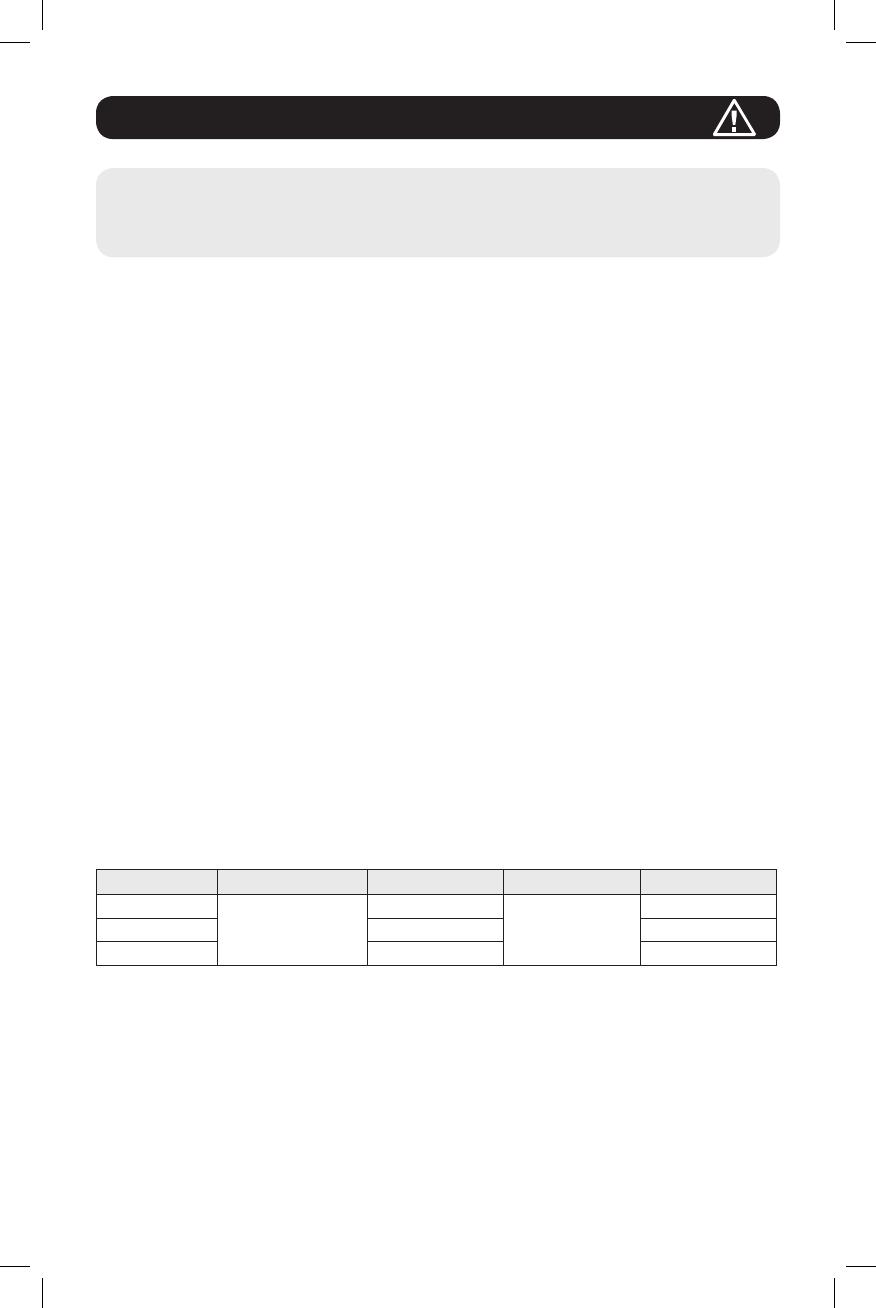
1.4 Battery Warnings
UPS Rating Built-in Batteries Battery Qty. Battery Type Battery Voltage
1kVA
Yes
2
9 Ah Sealed
Lead-Acid Battery
24Vdc
2kVA 4 48Vdc
3kVA 6 72Vdc
• The UPS does not require routine maintenance. Do not open the UPS for any reason. There are
no user-serviceable parts inside.
• Batteries can present a risk of electrical shock and burn from high short-circuit current. Observe
proper precautions. Do not dispose of the batteries in a fire. Do not open the UPS or batteries.
Do not short or bridge the battery terminals with any object. Disconnect and turn off the UPS
before performing battery replacement. Use tools with insulated handles. Battery replacement
should be performed only by authorized service personnel using the same number and type of
batteries (Sealed Lead-Acid). The batteries are recyclable. Refer to your local codes for disposal
requirements or visit http://www.tripplite.com/support/recycling-program for recycling information.
Tripp Lite offers a complete line of UPS System Replacement Battery Cartridges (R.B.C.).Visit
Tripp Lite on the Web at http://www.tripplite.com/products/battery-finder/ to locate the specific
replacement battery for your UPS.
18-09-252-93358B.indb 3 1/9/2019 2:19:26 PM


