Tripp Lite SMARTINT2200VS/SMARTINT3000VS UPS Инструкция по применению
- Категория
- Источники бесперебойного питания (UPS)
- Тип
- Инструкция по применению

1
Owner’s Manual
Intelligent, Line-Interactive
UPS Systems
(Tower Configuration)
• 230V Input • 2200VA - 3000VA Capacities
Extended-Run Options*
Models: SMARTINT2200VS & SMARTINT3000VS
* SMARTINT3000VS model
1111 W. 35th Street, Chicago, IL 60609 USA • www.tripplite.com/support
Copyright © 2019 Tripp Lite. All rights reserved. SmartPro
®
is a registered trademark of Tripp Lite.
Important Safety Instructions 2
Quick Installation 3
Optional Installation 4
Basic Operation 5
Storage & Service 10
Specifications 11
Español 12
Français 24
Русский 36
18-08-322-932245.indb 1 5/3/2019 1:44:51 PM

2
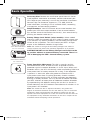
Important Safety Instructions
UPS Location Warnings
• Install your UPS indoors, away from excess moisture or heat, conductive contaminants,
dust or direct sunlight.
• For best performance, keep the indoor temperature between 32º F and 104º F
(0º C and 40º C).
• Leave adequate space around all sides of the UPS for proper ventilation.
• Do not install the UPS near magnetic storage media, as this may result in data
corruption.
UPS Connection Warnings
• Connect your UPS directly to a properly grounded AC power outlet. Do not plug the UPS
into itself; this will damage the UPS.
• Do not modify the UPS’s plug, and do not use an adapter that would eliminate the
UPS’s ground connection.
• Do not use extension cords to connect the UPS to an AC outlet. Your warranty will be
voided if anything is used to connect your UPS to an outlet.
• If the UPS receives power from a motor-powered AC generator, the generator must
provide clean, filtered, computer-grade output.
Equipment Connection Warnings
• Do not use Tripp Lite UPS Systems for life support applications in which a malfunction
or failure of a Tripp Lite UPS System could cause failure or significantly alter the
performance of a life-support device.
• Do not connect surge suppressors or extension cords to the output of your UPS.
Battery Warnings
• Batteries can present a risk of electrical shock and burn from high short-circuit current.
Observe proper precautions. Do not dispose of the batteries in a fire. Do not open the
UPS or batteries. Do not short or bridge the battery terminals with any object. Unplug
and turn off the UPS before performing battery replacement. Use tools with insulated
handles. There are no user-serviceable parts inside the UPS. Battery replacement should
be performed only by authorized service personnel using the same number and type of
batteries (sealed Lead-Acid). The batteries are recyclable. Refer to your local codes for
disposal requirements or in the USA only call 1-800-SAV-LEAD or 1-800-8-BATTERY
(1-800-8-228-8379) or visit www.rbrc.com for recycling information. Tripp Lite offers a
complete line of UPS System Replacement Battery Cartridges (R.B.C.). Visit Tripp Lite on
the Web at www.tripplite.com to locate the specific replacement battery for your UPS.
• If your UPS model is equipped with an external battery connector, only connect
Tripp Lite battery packs of the appropriate type and correct voltage. Do not connect or
disconnect external batteries while the UPS is operating from battery.
SAVE THESE INSTRUCTIONS
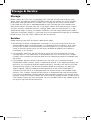
This manual contains instructions and warnings that should be followed during
the installation, operation and storage of all Tripp Lite UPS Systems.
18-08-322-932245.indb 2 5/3/2019 1:44:51 PM

3
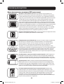
Quick Installation
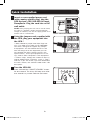
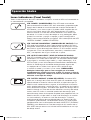
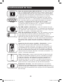
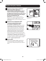
1
Insert a user-supplied power cord
(with country-specific plug) into the
UPS System’s IEC-320-C20 AC Input
Receptacle. Plug the cord into an AC
wall outlet.
NOTE! After you plug the UPS into a live AC outlet,
the UPS (in “Standby” mode) will automatically
charge its batteries, but will not supply power to its
outlets until it is turned ON.
2
Using the jumper cords supplied with
the UPS, plug your equipment into
the UPS.*
* Order additional jumper cords from Tripp Lite.
Call (773) 869-1234; order part # P004-006.
Your UPS is designed to support only comput-
er equipment. You will overload the UPS if the
total VA ratings for all the equipment you con-
nect exceeds the UPS’s Output Capacity (see
Specifications). To find your equipment’s VA rat-
ings, look on their nameplates. If the equipment
is listed in amps, multiply the number of amps by
230 to determine VA. (Example: 1 amp × 230 =
230 VA). If you are unsure if you have overloaded
the UPS’s outlets, see “OUTPUT LOAD LEVEL” LED
description.
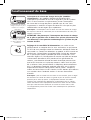
3
Turn the UPS ON.
Press and hold the “ON/OFF/STANDBY” button
for one second. The alarm will beep once after
one second has passed. Release the button.
1
2
3
Shown: SMARTINT2200VS
18-08-322-932245.indb 3 5/3/2019 1:44:52 PM

4
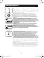
Optional Installation
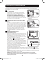
These connections are optional. Your UPS will function properly without these connections.
Shown: SMARTINT2200VS
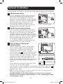
1
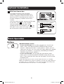
USB Communications
Use the included USB cable to connect the USB
port of your computer to the USB port of your
UPS. Install on your computer the Tripp Lite
PowerAlert Software appropriate to your computer’s
operating system. Your UPS may feature additional
communications ports; these ports may also
be connected to additional computers which
have PowerAlert Software installed. Consult your
PowerAlert manual for more information.
2
RS-232 Serial Communications
If your computer is equipped with a DB9 serial
port, use the included serial cable to connect the
DB9 port of your computer to the DB9 port of
your UPS. Install on your computer the Tripp Lite
PowerAlert Software appropriate to your computer’s
operating system. Your UPS may feature additional
communications ports; these ports may also
be connected to additional computers which
have PowerAlert Software installed. Consult your
PowerAlert manual for more information.
3
External Battery Connection
(select models)
Your UPS comes with a robust internal battery
system; external batteries are only needed to
extend runtime. Adding external batteries will
increase recharge time as well as runtime.
The illustration (see
3a
) shows the location of your
UPS’s External Battery Connector, where you will
insert the battery pack cable. Complete installation
instructions for your battery pack appear in the
battery pack’s owner’s manual. Make sure that
cables are fully inserted into their connectors. Small
sparks may result during battery connection; this is
normal.
Do not connect or disconnect battery packs when
the UPS is running on battery power.
1
2
3a
3b
If you connect any external batteries, set the Battery Charge Level Switch (see
3b
) to
the up position. This will increase your UPS’s charger output so the additional
batteries charge faster.
Note: the switch to the right of the Battery Charge Level Switch is inactive and will not
affect UPS operation regardless of its position.
CAUTION! DO NOT set the Battery Charge Level Switch to the up position
without an external battery connected. There is a risk of damaging the UPS’s
internal battery system.
18-08-322-932245.indb 4 5/3/2019 1:44:53 PM

5
Optional Installation
Basic Operation
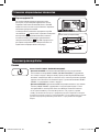
4
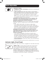
EPO Port Connection
This optional feature is only for those
applications which require connection to a
facility’s Emergency Power Off (EPO) circuit.
When the UPS is connected to this circuit, it
enables emergency shutdown of the UPS’s
inverter.
Using the cable provided, connect the EPO port
of your UPS (see
4a
) to a user-supplied
normally closed or normally open switch
according to the circuit diagram (see
4b
). The
EPO port is not a phone line surge suppressor;
do not connect a phone line to this port.
OPTION 1: USER SUPPLIED NORMALLY CLOSED SWITCH
OPTION 2: USER SUPPLIED NORMALLY OPEN SWITCH
RJ11
PLUG
5
4
3
2
NO CONNECTION
4-5 JUMPER
N.C. EPO SWITCH
RJ11
PLUG
5
4
3
2
NO CONNECTION
N.O. EPO SWITCH
4a
4b
Buttons
“ON/OFF/STANDBY” Button
• To turn the UPS ON: with the UPS plugged into a live AC wall
outlet,* press and hold the ON/OFF/STANDBY button for one
second.** Release the button. If utility power is absent, you can
“cold-start” the UPS (i.e.: turn it ON and supply power for a limited
time from its batteries***) by pressing and holding the ON/OFF/
STANDBY button for one second.**
• To turn the UPS OFF: with the UPS ON and receiving utility
power, press and hold the ON/OFF/STANDBY button for one sec-
ond.** Then unplug the UPS from the wall outlet. The UPS will be
completely OFF.
* After you plug the UPS into a live AC outlet, the UPS (in “Standby”
mode) will automatically charge its batteries, but will not supply power to
its outlets until it is turned ON. ** The alarm will beep once briefly after
the indicated interval has passed. *** If fully charged.
18-08-322-932245.indb 5 5/3/2019 1:44:53 PM

6
Basic Operation
“MUTE/TEST” Button
• To Silence (or “Mute”) UPS Alarms: briefly press and release the
MUTE/TEST button.
• To Run a Self-Test: with your UPS plugged in and turned ON,
press and hold the MUTE/TEST button for two seconds.* Continue
holding the button until the alarm beeps several times and the
UPS performs a self test. See “Results of a Self-Test” below.
Note: you can leave connected equipment on during a self-test. Your
UPS, however, will not perform a self-test if the UPS is not turned on
(see “ON/OFF/STANDBY” Button description).
CAUTION! Do not unplug your UPS to test its batteries. This
will remove safe electrical grounding and may introduce a
damaging surge into your network connections.
Results of a Self-Test: the test will last approximately 10 seconds
as the UPS switches to battery to test its load capacity and battery
charge.
• If the “OUTPUT LOAD LEVEL” LED remains lit red and the
alarm continues to sound after the test, the UPS’s outlets are
overloaded. To clear the overload, unplug some of your equipment
and run the self-test repeatedly until the “OUTPUT LOAD LEVEL”
LED is no longer lit red and the alarm is no longer sounding.
CAUTION! Any overload that is not corrected by the user
immediately following a self-test may cause the UPS to shut
down and cease supplying output power in the event of a
blackout or brownout.
• If the “BATTERY WARNING” LED remains lit and the alarm
continues to sound after the test, the UPS batteries need to be
recharged or replaced. Allow the UPS to recharge continuously for
12 hours, and repeat the self-test. If the LED remains lit, contact
Tripp Lite for service. If your UPS requires battery replacement,
visit www.tripplite.com to locate the specific Tripp Lite replacement
battery for your UPS.
* The alarm will beep once briefly after the indicated interval has passed.
Indicator Lights (Front Panel)
All Indicator Light descriptions apply when the UPS is plugged into a wall outlet and turned
ON.
“POWER” LED: this green LED lights continuously when the UPS
is ON and supplying connected equipment with AC power from
a utility source. The LED flashes and an alarm sounds (4 short
beeps followed by a pause) to indicate the UPS is operating from
its internal batteries during a blackout or severe brownout. If the
blackout or severe brownout is prolonged, you should save files and
shut down your equipment since internal battery power will eventually
be depleted. See “BATTERY CHARGE” LED description.
18-08-322-932245.indb 6 5/3/2019 1:44:54 PM

7
Basic Operation
“VOLTAGE CORRECTION” LED: this green LED lights continuously
whenever the UPS is automatically correcting high or low AC voltage
on the utility line without the assistance of battery power. The UPS
will also emit a slight clicking noise. These are normal, automatic
operations of the UPS, no action is required on your part.
“OUTPUT LOAD LEVEL” LED: this multicolored LED indicates the
approximate electrical load of equipment connected to the UPS’s AC
outlets. It will turn from green (light load) to yellow (medium load)
to red (overload). If the LED is red (either illuminated continuously
or flashing), clear the overload immediately by unplugging some of
your equipment from the outlets until the LED changes from red to
yellow (or green) and the alarm is no longer sounding. CAUTION!
Any overload that is not corrected by the user immediately may
cause the UPS to shut down and cease supplying output power
in the event of a blackout or brownout.
“BATTERY CHARGE” LED: when the UPS is operating from utility
power, this LED indicates the approximate charge state of the
UPS’s internal batteries: red indicates the batteries are beginning to
charge; yellow indicates the batteries are roughly midway through
charging; and green indicates the batteries are fully charged. When
the UPS is operating from battery power during a blackout or severe
brownout, this LED indicates the approximate amount of energy
(ultimately affecting runtime) which the UPS’s batteries will provide:
red indicates a low level of energy; yellow indicates a medium level
of energy; and green indicates a high level of energy. Since the
runtime performance of all UPS batteries will gradually deplete over
time, it is recommended that you periodically perform a self-test (see
MUTE/TEST Button description) to determine the energy level of your
UPS batteries BEFORE a blackout or severe brownout occurs. During
a prolonged blackout or severe brownout, you should save files
and shut down your equipment since battery power will eventually
be depleted. When the LED turns red and an alarm sounds
continuously, it indicates the UPS’s batteries are nearly out of power
and UPS shut down is imminent.
“BATTERY WARNING” LED: this LED lights red and an alarm sounds
intermittently after you initiate a self test (See “MUTE/TEST” Button
description) to indicate the UPS batteries need to be recharged or
replaced. Allow the UPS to recharge continuously for 12 hours, and
repeat the self-test. If the LED continues to light, contact Tripp Lite
for service. If your UPS requires battery replacement, visit
www.tripplite.com to locate the specific Tripp Lite replacement
battery for your UPS.
18-08-322-932245.indb 7 5/3/2019 1:44:54 PM

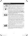
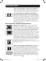
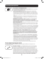
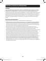
8
EPO
IEC320-C19 (female)
IEC320-C13 (female)
USB port
RS-232 (DB9 port)
IEC320-C20 (male)
Basic Operation
Other UPS Features (Back Panel)
AC Output Receptacles: Your UPS features IEC320-C13 AC outlets,
and select models also feature IEC320-C19 AC outlets. These
output receptacles provide your connected equipment with AC line
power during normal operation and battery power during blackouts
and brownouts. The UPS protects equipment connected to these
receptacles against damaging surges and line noise. If you have
a serial or USB connection to your UPS, you can remotely reboot
connected equipment by turning the receptacles OFF and ON using
Tripp Lite’s PowerAlert Software. Select models have their receptacles
divided into one or more load banks (labeled “LOAD 1,” etc.) which
may be remotely switched OFF and ON using Tripp Lite UPS software
without interrupting power to equipment connected to the other
outlets. See software instructions for details.
AC Input Receptacle: This receptacle accepts a user-supplied power
cord (with country-specific plug).
Communication Ports (USB or RS-232): These ports connect
your UPS to any workstation or server. Use with Tripp Lite’s
PowerAlert Software and included cables to enable your computer
to automatically save open files and shut down equipment during a
blackout. Also use PowerAlert Software to monitor a wide variety of
AC line power and UPS operating conditions. Consult your PowerAlert
Software manual or contact Tripp Lite Customer Support for more
information. See “USB Communications” and “RS-232 Serial
Communications” in the “Optional Installation” section for installation
instructions.
EPO Port (select models): Your UPS features an EPO port that may
be used to connect the UPS to a contact closure switch to enable
emergency inverter shutdown. See “EPO Port Connection” in the
“Optional Installation” section.
Battery Replacement Door: Under normal conditions, the original
battery in your UPS will last several years. Battery replacement
should be performed only by qualified service personnel. Refer to
“Battery Warnings” in the Safety section. Should your UPS require
battery replacement, visit Tripp Lite on the Web at www.tripplite.com
to locate the specific replacement battery for your UPS.
External Battery Connector (select models): Use to connect
one or more Tripp Lite battery packs for additional runtime. Refer to
Specifications and/or the label next to the connector to determine
the appropriate variety of battery pack to use. Refer to the battery
pack instruction manual for complete installation information and
important safety warnings. See “External Battery Connection” in the
“Optional Installation” section.
18-08-322-932245.indb 8 5/3/2019 1:44:54 PM

9
Basic Operation
Accessory Slot: Remove the small cover panel from this slot to
install optional accessories to remotely monitor and control your
UPS. Refer to your accessory’s manual for installation instructions.
Contact Tripp Lite Customer Support at (773) 869-1234 for
more information, including a list of available SNMP, networking
management and connectivity products.
Output Breakers: Your UPS features one or more breakers that
protect your UPS from output overload. If one or more breakers
trip, remove some of the load on the circuit(s), then reset them by
pressing the breaker switch(es) in.
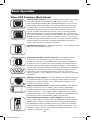
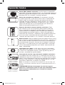
Battery Charge Level Switch (select models): Select models
feature a switch that controls the UPS system’s battery charge rate.
If you connect any external batteries, set the Battery Charge Level
Switch to the up position. This will increase your UPS’s charger
output so the additional batteries charge faster.
Note: the switch to the right of the Battery Charge Level Switch is
inactive and will not affect UPS operation regardless of its position.
CAUTION! DO NOT set the Battery Charge Level Switch to the
up position without an external battery connected. There is a
risk of damaging the UPS’s internal battery system.
Power Sensitivity Adjustment: This dial is normally set fully
counterclockwise, which enables the UPS to provide maximum
protection against waveform distortions in its AC input. When such
distortion occurs, the UPS will normally switch to providing PWM sine
wave power from its battery reserves for as long as the distortion
is present. In areas with poor utility power or where the UPS’s
input power comes from a backup generator, chronic waveform
distortion could cause the UPS to switch to battery too frequently,
draining its battery reserves. You may be able to reduce how often
your UPS switches to battery due to moderate waveform distortion
by experimenting with different settings for this dial. As the dial is
turned clockwise, the UPS becomes more tolerant of variations in its
input power’s AC waveform.
Note: The further the dial is adjusted clockwise, the greater the
degree of waveform distortion the UPS will allow to pass to connected
equipment. When experimenting with different settings for this dial,
operate connected equipment in a safe test mode so that the effect on
the equipment of any waveform distortions in the UPS’s output can be
evaluated without disrupting critical operations.
Charge Rate Setting
(when External Batteries
are not connected)
Charge Rate Setting
(when External Batteries
are connected)
DELAY
NORM
18-08-322-932245.indb 9 5/3/2019 1:44:55 PM

10
Storage
Before storing your UPS, turn it completely OFF: with the UPS ON and receiving utility
power, press and hold the ON/OFF/STANDBY button for one second (an alarm will beep
once briefly after the interval has passed); then, unplug the UPS from the wall outlet.
If you store your UPS for an extended period of time, recharge the UPS batteries once
every three months: plug the UPS into a wall outlet; allow it to charge for up to 4 hours;
and then unplug it and place it back in storage. Note: after you plug the UPS in, it will
automatically begin charging its batteries; however, it will not supply power to its outlets
(see Quick Installation section). If you leave your UPS batteries discharged for an extended
period of time, they will suffer a permanent loss of capacity.
Service
Before returning your UPS for service, follow these steps:
1. Review the installation and operation instructions in this manual to ensure that the
service problem does not originate from a misreading of the instructions. Also, check
that the UPS System’s circuit breaker(s) are not tripped. This is the most common
cause of service inquiries which can be easily remedied by following the resetting
instructions in this manual.
2. If the problem continues, do not contact or return the UPS to the dealer. Instead,
call Tripp Lite at (773) 869-1233. A service technician will ask for the UPS’s model
number, serial number and purchase date and will attempt to correct the problem over
the phone.
3. If the problem requires service, the technician will issue you a Returned Material
Authorization (RMA) number, which is required for service. If you require packaging, the
technician can arrange to send you proper packaging. Securely pack the UPS to avoid
damage during shipping. Do not use Styrofoam beads for packaging. Any damages
(direct, indirect, special, incidental or consequential) to the UPS incurred during
shipment to Tripp Lite or an authorized Tripp Lite service center is not covered under
warranty. UPS Systems shipped to Tripp Lite or an authorized Tripp Lite service center
must have transportation charges prepaid. Mark the RMA number on the outside of the
package. If the UPS System is within the 2-year warranty period, enclose a copy of your
sales receipt. Return the UPS for service using an insured carrier to the address given to
you by the Tripp Lite service technician.
Storage & Service
18-08-322-932245.indb 10 5/3/2019 1:44:55 PM

11
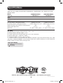
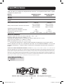
Tripp Lite has a policy of continuous improvement. Specifications are subject to change
without notice.
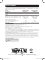
Model: SMARTINT2200VS SMARTINT3000VS
Series #: AGSM4839 AGSM4840
Input
Nominal Voltage/Frequency: 230VAC 50/60 Hz 230VAC 50/60 Hz
Output
Capacity (VA/Watts): 2200/1600 3000/2250
On Line Nominal Voltage/Waveform: 230VAC/sine wave 230VAC/sine wave
On Battery Nominal Voltage/Waveform: 230VAC/PWM sine wave 230VAC/PWM sine wave
Battery Runtime (Half Load/Full Load) Minutes: 19/7 14/4+
Battery Recharge Time: 2-4 hrs. 2-4 hrs.
Approvals: CE, GOST, SASO, IRAM CE, GOST, SASO, IRAM
ALL UNITS:
Voltage-Regulated Output Voltage Range: -18% / +8%.
On-Battery Output Voltage Range: ± 5 %.
AC Surge Suppression (exceeds IEEE 587 Cat. A & B standards);
AC Noise Attenuation (>40 dB at 1MHz);
AC Protection Modes (H to N, H to G, N to G).
“+” Battery runtime can be extended with addition of optional Tripp Lite External Battery Pack (sold
separately). SMARTINT3000VS uses BP48V18 battery pack. External battery will increase both the
battery runtime and the battery recharge time.
Note on Labeling
Two symbols are used on the label.
V~ : AC Voltage
V : DC Voltage
Specifications
1111 W. 35th Street, Chicago, IL 60609 USA • www.tripplite.com/support
18-08-322 93-2245_revB
18-08-322-932245.indb 11 5/3/2019 1:44:56 PM

12
Manual del propietario
Inteligentes e interactivos
con la línea
(Para montaje en torre)
• Entrada 230 V • Capacidad entre 2200 y 3000 VA
• Opciones de tiempo de respaldo extendido*
Modelos: SMARTINT2200VS y SMARTINT3000VS
* Modelo SMARTINT3000VS
1111 W. 35th Street, Chicago, IL 60609 USA • www.tripplite.com/support
Copyright © 2019 Tripp Lite.
Todos los derechos reservados SmartPro
®
es una marca comercial registrada de Tripp Lite.
Instrucciones de seguridad importantes 13
Instalación rápida 14
Instalación opcional 16
Operación básica 16
Almacenamiento y Servicio 22
Especificaciones 23
English 1
Français 24
Русский 36
18-08-322-932245.indb 12 5/3/2019 1:44:56 PM

13
Instrucciones de seguridad importantes
Advertencias sobre la ubicación del UPS
• Instale su UPS bajo techo, lejos de la humedad, el calor, los contaminantes
conductores, el polvo o la luz solar directa.
• Para un mejor funcionamiento, mantenga la temperatura en ambientes interiores entre
32º F y 104º F (0º C y 40º C).
• Deje una cantidad adecuada de espacio alrededor de todos los lados del UPS para una
adecuada ventilación.
• No instale el UPS cerca de medios de almacenamiento magnético ya que puede dañar
los datos.
Advertencias sobre la conexión del UPS
• Conecte su UPS directamente a una toma de corriente de CA puesta a tierra
apropiadamente. No conecte el UPS a si mismo ya que podría dañarse.
•
No modifique el enchufe del UPS ni emplee un adaptador que elimine su conexión a tierra.
• No use cordones de extensión para conectar el UPS a una toma de CA. Su garantía
será anulada si utiliza algo para conectar su UPS a una toma de corriente.
• Si el UPS recibe energía de un generador de CA accionado por motor, el generador
debe proporcionar una salida limpia y filtrada de grado computadora.
Advertencias sobre la conexión de equipos
• No utilice sistemas UPS de Tripp Lite para aplicaciones de soporte de vida en las que
el funcionamiento defectuoso o una falla de un UPS Tripp Lite pudiera causar la falla o
una alteración importante en el funcionamiento de un dispositivo de soporte de vida.
•
No conecte supresores de sobretensiones ni cordones de extensión a la salida de su UPS.
Advertencias sobre la batería
•
Las baterías presentan un peligro de choque eléctrico y quemaduras como producto de
las altas corrientes de cortocircuito. Observe las precauciones apropiadas. No deseche
las baterías en un incinerador. No abra el UPS ni las baterías. No ponga los terminales de
una batería en corto o en puente con ningún objeto. Apague y desconecte el UPS antes
de reemplazar las baterías. Use herramientas con mangos aislados. No hay piezas que
el usuario pueda reparar dentro de un UPS. El reemplazo de baterías debe ser realizado
solamente por personal de servicio autorizado usando el mismo número y tipo de baterías
(plomo-ácido, selladas). Las baterías son reciclables. Consulte la reglamentación local
para los requisitos de disposición de desechos; en los EE.UU. llame al 1-800-SAV-LEAD
o al 1-800-8-BATTERY (1-800-8-228-8379) o visite www.rbrc.com para obtener
información sobre el proceso de reciclaje. Tripp Lite ofrece una línea completa de
cartuchos de reemplazo de batería para UPS (R.B.C.). Visite la página web de Tripp Lite
en www.tripplite.com para localizar la batería de reemplazo específica para su UPS.
• Si su modelo de UPS está equipado con un conector de batería externa, sólo conecte
bancos de baterías Tripp Lite del tipo apropiado y el voltaje correcto. No conecte ni
desconecte baterías externas mientras el UPS esté operando con energía de baterías.
GUARDE ESTAS INSTRUCCIONES
Este manual contiene instrucciones y advertencias que deben seguirse durante
la instalación, operación y el almacenamiento de todos los UPS de Tripp Lite.
18-08-322-932245.indb 13 5/3/2019 1:44:56 PM

14
Instalación rápida
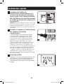
1
Introduzca un cordón de
alimentación suministrado por el
usuario (con un enchufe adecuado
para su país) en la toma de entrada
IEC-320-C20 de CA del UPS. Enchufe
el cordón en la toma de corriente de
pared de CA.
¡NOTA! Después de conectar el UPS en una toma
de CA con energía, el equipo (en modo “Standby”)
cargará automáticamente sus baterías, pero no
suministrará energía a sus salidas hasta que sea
encendido.
2
Enchufe su equipo en el UPS usando
los cordones de puente
suministrados.*
* Ordene cordones de puente adicionales de
Tripp Lite. Llame al (773) 869-1234; ordene
el componente # P004-006. Su UPS sólo
está diseñado para dar soporte a equipos de
informática. Si la capacidad total en VA para
todos los equipos conectados a las salidas
excede la capacidad de salida del UPS (vea las
Especificaciones), éste se sobrecargará. Para
averiguar la capacidad de sus equipos en VA,
revise sus placas. Si la capacidad del equipo está
indicada en amperios, multiplique los amperios
por 230 para determinar los VA. (Ejemplo: 1 A
× 230 V = 230 VA) Si no está seguro de si ha
sobrecargado las salidas del UPS, consulte la
descripción del LED “OUTPUT LOAD LEVEL” (Nivel
de carga de salida).
3
Encienda el UPS.
Presione y mantenga presionado el botón “ON/
OFF/STANDBY” (Encendido/Apagado/Reserva)
durante un segundo. La alarma emitirá un
pitido después de pasado un segundo. Suelte
el botón.
1
2
3
Mostrado: SMARTINT2200VS
18-08-322-932245.indb 14 5/3/2019 1:44:56 PM

15
Instalación opcional
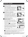
Estas conexiones son opcionales. Su UPS funcionará correctamente sin ellas.
Mostrado: SMARTINT2200VS
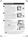
1
Comunicaciones USB
Use el cable USB incluido para conectar el puerto
USB de su computadora al puerto USB de su UPS.
Instale en su computadora el software PowerAlert
de Tripp Lite apropiado para su sistema operativo.
Su UPS puede tener puertos adicionales de
comunicaciones; estos puertos también pueden
estar conectados a computadoras adicionales con el
software PowerAlert instalado. Consulte su manual
de PowerAlert para mayor información.
2
Comunicaciones serie RS-232
Si su computadora cuenta con un puerto serie DB9,
conéctelo con el puerto DB9 de su UPS usando el
cable serie incluido. Instale en su computadora el
software PowerAlert de Tripp Lite apropiado para
su sistema operativo. Su UPS puede tener puertos
adicionales de comunicaciones; estos puertos también
pueden conectarse a computadoras adicionales con el
software PowerAlert instalado. Consulte su manual de
PowerAlert para mayor información.
3
Conexión de batería externa
(modelos exclusivos)
Su UPS incluye un robusto sistema de batería
interna; las baterías externas sólo son necesarias
para prolongar el tiempo de respaldo. Al agregar
baterías externas, aumentará el tiempo de recarga y
el tiempo de respaldo.
La ilustración (vea
3a
) muestra la ubicación del
conector de batería externa de su UPS, donde debe
introducir el cable del banco de baterías. Vea las
instrucciones completas de instalación para su
banco de baterías en el manual del propietario del
banco de baterías. Asegúrese que los cables estén
introducidos completamente en sus conectores.
Durante la conexión de la batería pueden producirse
pequeñas chispas; esto es normal.
1
2
3a
3b
No conecte ni desconecte bancos de baterías cuando el UPS esté funcionando con
energía de las baterías.
Si conecta alguna batería externa, fije el Interruptor de nivel de carga de batería (ver
3b
) en la posición de arriba. Esto aumentará la salida del cargador del UPS a fin de
que las baterías adicionales se carguen más rápido.
Nota: el interruptor a la derecha del interruptor de nivel de carga está inactivo y no
afectará la operación del UPS, independientemente de su posición.
¡PRECAUCIÓN! NO fije el Interruptor de nivel de carga de batería en la posición
superior sin una batería externa conectada. Podría dañarse el sistema de la
batería interna del UPS.
18-08-322-932245.indb 15 5/3/2019 1:44:57 PM

16
Instalación opcional
Operación básica
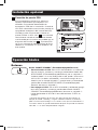
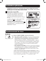
4
Conexión de puerto EPO
Esta característica opcional es sólo para
aquellas aplicaciones que requieran una
conexión al circuito de desconexión de
emergencia (EPO) de la instalación. Cuando el
UPS está conectado a este circuito, permite el
apagado de emergencia del inversor del UPS.
Usando el cable suministrado, conecte el
puerto EPO de su UPS (vea
4a
) a un contacto
normalmente cerrado o normalmente abierto
suministrado por el usuario, de acuerdo con el
diagrama del circuito (vea
4b
). El puerto EPO
no es un supresor de sobretensiones de línea
telefónica; no conecte una línea telefónica en
este puerto.
4a
4b
Botones
Botón “ON/OFF/STANDBY” (Encendido/Apagado/Reserva)
• Para encender el UPS: Con el UPS conectado en una toma de
CA con energía*, presione y mantenga presionado el botón ON/
OFF/STANDBY (Encendido/Apagado/Reserva) por un segundo.**
Suelte el botón. Si no hay energía de la red, puede “arrancar en
frío” el UPS (es decir, encenderlo y suministrar energía de sus
baterías por un tiempo limitado***) presionando y manteniendo
presionado el botón ON/OFF/STANDBY (Encendido/Apagado/
Reserva) durante un segundo.**
• Para apagar el UPS: Con el UPS encendido y recibiendo energía
de la red, presione y mantenga presionado el botón ON/OFF/
STANDBY (Encendido/Apagado/Reserva) durante un segundo.**
Luego desconecte el UPS de la toma de corriente. El UPS se
apagará.
* Después de conectar el UPS en una toma de CA con energía, el
equipo (en modo “Standby”) cargará automáticamente sus baterías,
pero no suministrará energía a sus salidas hasta que sea encendido. **
La alarma emitirá un pitido brevemente después de pasado el intervalo
indicado. *** Si está completamente cargada.
18-08-322-932245.indb 16 5/3/2019 1:44:57 PM

17
Operación básica
Botón “MUTE/TEST” (SILENCIO/PRUEBA)
• Para silenciar las alarmas UPS: Presione brevemente el botón
MUTE/TEST (SILENCIO/PRUEBA) y luego suéltelo.
• Para ejecutar una auto-prueba: Con su UPS conectado y
encendido, presione y mantenga presionado el botón MUTE/TEST
(Silencio/Prueba) por dos segundos.* Siga presionando el botón
hasta que la alarma suene varias veces y el UPS realice una auto-
prueba. Vea “Resultados de una auto-prueba” más abajo.
Nota: Puede dejar equipos conectados durante una auto-prueba.Sin
embargo, su UPS, no realizará una auto-prueba si no está encendido
(vea la descripción del Botón “ON/OFF/STANDBY”).
¡PRECAUCIÓN! No desconecte su UPS para probar sus baterías.
Esto eliminaría la conexión de seguridad a tierra y podría
introducir una sobretensión dañina en sus conexiones de red.
Resultados de una auto-prueba: La prueba durará cerca de
10 segundos mientras el UPS conmuta a batería para probar su
capacidad de carga y la recarga de la batería.
• Si el LED “OUTPUT LOAD LEVEL” (NIVEL DE CARGA DE SALIDA)
permanece encendido rojo y la alarma continúa sonando después
de la prueba, las salidas del UPS están sobrecargadas. Para
eliminar la sobrecarga, desconecte algo de su equipo y ejecute la
auto-prueba repetidamente hasta que el LED ya no esté encendido
rojo y la alarma ya no esté sonando.
¡PRECAUCIÓN! Cualquier sobrecarga que no sea corregida por
el usuario inmediatamente después de una auto-prueba puede
causar que el UPS se apague y deje de suministrar energía de
salida en el caso de un falla del servicio eléctrico o una baja
de voltaje.
• Si el LED “BATTERY WARNING” (ADVERTENCIA DE BATERÍA) sigue
encendido y la alarma continúa sonando después de la prueba, l
as baterías del UPS deben recargarse o reemplazarse. Permita que
el UPS se recargue continuamente por 12 horas y repita la auto-
prueba. Si el LED permanece encendido, contacte con
Tripp Lite para obtener servicio. Si su UPS requiere el reemplazo
de su batería, visite www.tripplite.com para localizar la batería de
reemplazo Tripp Lite específica para su UPS.
* La alarma emitirá un breve pitido después de pasado el intervalo indicado.
18-08-322-932245.indb 17 5/3/2019 1:44:57 PM

18
Operación básica
Luces indicadoras (Panel frontal)
Todas las descripciones de luces indicadoras se aplican cuando el UPS está conectado en
un tomacorriente y encendido.
LED “POWER” (ALIMENTACIÓN): Este LED verde se enciende
permanentemente cuando el UPS está encendido y proporcionando
energía de CA desde el suministro de red al equipo conectado. El
LED destella y una alarma suena (4 pitidos cortos seguidos de una
pausa) para indicar que el UPS está operando con sus baterías
internas durante una falla del servicio eléctrico o una severa baja
de voltaje. Si la falla o la baja de voltaje es muy prolongada, debe
guardar sus archivos y apagar su equipo ya que la energía de la
batería interna eventualmente se agotará. Vea la descripción del LED
“BATTERY CHARGE” (CARGA DE BATERÍA).
LED “VOLTAGE CORRECTION” (CORRECCIÓN DE VOLTAJE): Este
LED verde se enciende en forma permanente cuando el UPS está
corrigiendo automáticamente el voltaje de CA alto o bajo en la línea
de la red sin ayuda de energía de baterías. El UPS también emitirá
un ligero clic. Estas son operaciones normales y automáticas del
UPS y no requieren de ninguna acción de su parte.
LED “OUTPUT LOAD LEVEL” (NIVEL DE CARGA DE SALIDA):
Este LED multicolor indica la carga eléctrica aproximada del equipo
conectado a las salidas de CA del UPS. Se encenderá desde verde
(carga ligera) a amarillo (carga media) y a rojo (sobrecarga). Si el
LED está rojo (ya sea iluminado permanentemente o destellando),
elimine la sobrecarga de inmediato desconectando algunos de
sus equipos de las salidas hasta que el LED cambie de rojo
a amarillo (o verde) y la alarma ya no suene. ¡PRECAUCIÓN!
Cualquier sobrecarga que no sea corregida por el usuario
inmediatamente puede causar que el UPS se apague y deje de
suministrar energía de salida en el caso de un falla del servicio
eléctrico o una baja de voltaje.
LED “BATTERY CHARGE” (CARGA DE BATERÍA): Cuando el UPS
opera con la energía de la red, este LED indica el estado de carga
aproximado de las baterías internas del UPS; el rojo indica que las
baterías están comenzando a cargarse, el amarillo que las baterías
están aproximadamente a media recarga, y el verde que las baterías
están totalmente cargadas. Cuando el UPS opera con energía de las
baterías durante una falla del servicio eléctrico o una baja de voltaje
severa, este LED indica la cantidad aproximada de energía (que
eventualmente afecta el tiempo de respaldo) que proporcionarán las
baterías del UPS; el rojo indica un bajo nivel de energía, el amarillo
un nivel mediano y el verde un nivel alto de energía. Ya que el
rendimiento del tiempo de respaldo de todas las baterías del UPS
se reducirá gradualmente, se recomienda realizar una auto-prueba
periódicamente (vea la descripción del botón MUTE/TEST (SILENCIO/
PRUEBA)) para determinar el nivel de energía de las baterías de su
UPS ANTES de que ocurra una falla del servicio eléctrico o una baja
de voltaje severa.
18-08-322-932245.indb 18 5/3/2019 1:44:57 PM

19
Operación básica
IEC320-C19 (female)
IEC320-C13 (female)
USB port
RS-232 (DB9 port)
IEC320-C20 (male)
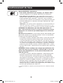
Otras funciones del UPS (Panel posterior)
Receptáculos de salida de CA: Su UPS tiene salidas de CA
IEC320-C13 y los modelos exclusivos también tienen salidas
IEC320-C19 AC. Estas tomas de salida proporcionan energía de la
línea de corriente alterna a su equipo conectado durante operación
normal, y energía de baterías durante fallas del servicio eléctrico
y bajas de voltaje. El UPS protege al equipo conectado en estas
tomas contra sobretensiones perjudiciales y ruido en la línea. Si
tiene una conexión serie o USB a su UPS, puede reiniciar en forma
remota el equipo conectado desactivando las salidas y activándolas
nuevamente, usando el software PowerAlert de Tripp Lite. Los
modelos exclusivos tienen sus receptáculos divididos en uno o más
bancos de carga (rotulados “LOAD 1” (CARGA 1), etc.) que pueden
ser encendidos y apagados en forma remota usando software de
UPS de Tripp Lite sin interrumpir la energía al equipo conectado a las
otras salidas. Vea las instrucciones del software para más detalles.
Receptáculo de entrada de CA: Este receptáculo acepta un
cordón de alimentación suministrado por el usuario (con un enchufe
adecuado para su país).
Puertos de comunicaciones (USB o RS-232): Estos puertos
conectan su UPS a cualquier estación de trabajo o servidor. Úselos
con el software PowerAlert de Tripp Lite y los cables incluidos
para permitir que su computadora guarde automáticamente los
archivos abiertos y apague el equipo durante una falla del servicio
eléctrico. También utilice PowerAlert para vigilar una amplia variedad
de condiciones de operación de la energía de la línea de CA y
del UPS. Consulte su manual de PowerAlert o contacte con el
Soporte al cliente de Tripp Lite para mayor información. Consulte
“Comunicaciones USB” y “Comunicaciones serie RS-232” en la
sección “Instalación opcional” para obtener información sobre las
instrucciones de instalación.
Durante una falla prolongada o una severa baja de voltaje, debe
guardar sus archivos y apagar su equipo ya que la energía de
baterías se agotará finalmente. Si el LED se enciende rojo y una
alarma suena en forma continua, significa que las baterías del UPS
están casi sin energía y es inminente que el UPS se apague.
LED “BATTERY WARNING” (ADVERTENCIA DE BATERÍA): Este
LED se enciende rojo y una alarma suena en forma intermitente
después de iniciar una auto-prueba (vea la descripción del botón
“MUTE/TEST” (SILENCIO/PRUEBA)) para indicar que las baterías del
UPS deben ser recargadas o reemplazadas. Permita que el UPS se
recargue continuamente por 12 horas y repita la auto-prueba. Si el
LED sigue encendido, contacte con Tripp Lite para que le brinden
servicio. Si su UPS requiere el reemplazo de su batería, visite
www.tripplite.com para localizar la batería de reemplazo Tripp Lite
específica para su UPS.
18-08-322-932245.indb 19 5/3/2019 1:44:58 PM

20
EPO
Operación básica
Puerto EPO (modelos exclusivos): Su UPS tiene un puerto EPO
que puede usarse para conectar el UPS a un contacto de cierre para
permitir el apagado de emergencia del inversor. Consulte “Conexión
de puerto EPO” en la sección “Instalación opcional”.
Puerta de reemplazo de la batería: En condiciones normales,
la batería original de su UPS durará varios años. El reemplazo de
baterías debe ser realizado solamente por personal de servicio
calificado. Consulte “Advertencias sobre la batería” en la sección
Seguridad. Si requiere reemplazar la batería de su UPS, visite la
página web de Tripp Lite en www.tripplite.com para localizar la
batería de reemplazo específica para su UPS.
Conector de batería externa (modelos exclusivos): Úselo
para conectar uno o más bancos de baterías externas de Tripp
Lite a fin de obtener tiempo de respaldo adicional. Consulte las
Especificaciones o la etiqueta junto al conector para determinar
el tipo correcto de banco de baterías a utilizar. Consulte toda la
información de instalación y advertencias de seguridad importantes
en el manual de instrucciones del banco de baterías. Consulte
“Conexión de batería externa” en la sección “Instalación opcional”.
Ranura auxiliar: Retire el pequeño panel de cubierta de esta ranura
para instalar los accesorios opcionales para vigilancia y control de su
UPS en forma remota. Consulte el manual de sus accesorios para
instrucciones de instalación. Contacte con el Soporte al cliente de
Tripp Lite al (773) 869-1234 para mayor información, incluyendo
una lista de productos disponibles para SNMP, administración de
redes y conectividad.
Interruptores de salida: Su UPS tiene uno o más interruptores
automáticos que protegen su UPS contra sobrecargas en la salida.
Si uno o más interruptores disparan, retire algo de carga de sus
circuitos y restablézcalos presionándolos.
Interruptor de nivel de carga de batería (modelos exclusivos):
Los modelos exclusivos cuentan con un interruptor que controla la
velocidad de carga de la batería del UPS. Si conecta alguna batería
externa, fije el Interruptor de nivel de carga de batería en la posición
de arriba. Esto aumentará la salida del cargador del UPS a fin de
que baterías adicionales se carguen más rápido.
Nota: el interruptor a la derecha del interruptor de nivel de carga está
inactivo y no afectará la operación del UPS, independientemente de su
posición.
¡PRECAUCIÓN! NO fije el Interruptor de nivel de carga de
batería en la posición de arriba sin que haya conectada alguna
batería externa. Podría dañarse el sistema de la batería
interna del UPS.
Ajuste de velocidad
de carga (sin baterías
externas conectadas)
Ajuste de velocidad
de carga (con baterías
externas conectadas)
18-08-322-932245.indb 20 5/3/2019 1:44:58 PM
Страница загружается ...
Страница загружается ...
Страница загружается ...
Страница загружается ...
Страница загружается ...
Страница загружается ...
Страница загружается ...
Страница загружается ...
Страница загружается ...
Страница загружается ...
Страница загружается ...
Страница загружается ...
Страница загружается ...
Страница загружается ...
Страница загружается ...
Страница загружается ...
Страница загружается ...
Страница загружается ...
Страница загружается ...
Страница загружается ...
Страница загружается ...
Страница загружается ...
Страница загружается ...
Страница загружается ...
Страница загружается ...
Страница загружается ...
Страница загружается ...
Страница загружается ...
-
 1
1
-
 2
2
-
 3
3
-
 4
4
-
 5
5
-
 6
6
-
 7
7
-
 8
8
-
 9
9
-
 10
10
-
 11
11
-
 12
12
-
 13
13
-
 14
14
-
 15
15
-
 16
16
-
 17
17
-
 18
18
-
 19
19
-
 20
20
-
 21
21
-
 22
22
-
 23
23
-
 24
24
-
 25
25
-
 26
26
-
 27
27
-
 28
28
-
 29
29
-
 30
30
-
 31
31
-
 32
32
-
 33
33
-
 34
34
-
 35
35
-
 36
36
-
 37
37
-
 38
38
-
 39
39
-
 40
40
-
 41
41
-
 42
42
-
 43
43
-
 44
44
-
 45
45
-
 46
46
-
 47
47
-
 48
48


Tripp Lite SMARTINT2200VS/SMARTINT3000VS UPS Инструкция по применению
- Категория
- Источники бесперебойного питания (UPS)
- Тип
- Инструкция по применению
Задайте вопрос, и я найду ответ в документе
Поиск информации в документе стал проще с помощью ИИ
на других языках
Похожие модели бренда
-
Tripp Lite SmartPro SMART500RT1U Инструкция по применению
-
-
-
-
Tripp Lite OMNIVSINT800/OMNIVSINT1000/OMNIVSINT1500XL UPS Инструкция по применению
-
Tripp Lite 230V SmartPro UPS Инструкция по применению
-
-
-
-