Indesit KN3G1(X)/UA Руководство пользователя

Категория
Кухонные плиты (варочные панели)
Тип
Руководство пользователя

Это руководство также подходит для

Contents
Installation, 2-5
Positioning and levelling
Electrical connections
Gas connection
Adapting to different types of gas
Technical data
Table of burner and nozzle specifications
Description of the appliance, 6
Overall view
Control panel
Start-up and use, 7
Using the hob
Using the oven
Oven cooking advice table
Precautions and tips, 12
General safety
Disposal
Respecting and conserving the environment
Maintenance and care, 13
Switching the appliance off
Cleaning the appliance
Gas tap maintenance
Replacing the oven light bulb
Assistance
Operating Instructions
COOKER
GB
English, 1 РУССКИЙ, 14
RS
KN3G1/ UA
KN3N11S/EU
Украінська,40
UA
Български
,,
,,
,28
BU
2
GB
! Before operating your new appliance please read
this instruction booklet carefully. It contains
important information concerning the safe installation
and operation of the appliance.
! Please keep these operating instructions for future
reference. Make sure that the instructions are kept
with the appliance if it is sold, given away or moved.
! The appliance must be installed by a qualified
professional according to the instructions provided.
! Any necessary adjustment or maintenance must be
performed after the cooker has been disconnected
from the electricity supply.
Room ventilation
The appliance may only be installed in permanently-
ventilated rooms, according to current national
legislation. The room in which the appliance is
installed must be ventilated adequately so as to
provide as much air as is needed by the normal gas
combustion process (the flow of air must not be
lower than 2 m
3
/h per kW of installed power).
The air inlets, protected by grilles, should have a
duct with an inner cross section of at least 100 cm
2
and should be positioned so that they are not liable
to even partial obstruction (
see figure A
).
These inlets should be enlarged by 100% - with a
minimum of 200 cm
2
- whenever the surface of the
hob is not equipped with a flame failure safety
device. When the flow of air is provided in an
indirect manner from adjacent rooms (
see figure B
),
provided that these are not communal parts of a
building, areas with increased fire hazards or
bedrooms, the inlets should be fitted with a
ventilation duct leading outside as described above.
AB
! After prolonged use of the appliance, it is
advisable to open a window or increase the speed of
any fans used.
Disposing of combustion fumes
The disposal of combustion fumes should be
guaranteed using a hood connected to a safe and
efficient natural suction chimney, or using an electric
fan that begins to operate automatically every time
the appliance is switched on (
see figure
).
! The liquefied petroleum gases are heavier than air
and collect by the floor, therefore all rooms
containing LPG cylinders must have openings
leading outside so that any leaked gas can escape
easily.
LPG cylinders, therefore, whether partially or
completely full, must not be installed or stored in
rooms or storage areas that are below ground level
(cellars, etc.). Only the
cylinder being used should be stored in the room;
this should also be kept well away from sources
of heat (ovens, chimneys, stoves) that may cause
the temperature of the cylinder to rise above 50°C.
Positioning and levelling
! It is possible to install the appliance alongside
cupboards whose height does not exceed that of the
hob surface.
! Make sure that the wall in contact with the back of
the appliance is made from a non-flammable, heat-
resistant material (T 90°C).
To install the appliance correctly:
Place it in the kitchen, dining room or the bed-sit
(not in the bathroom).
If the top of the hob is higher than the cupboards,
the appliance must be installed at least 200 mm
away from them.
If the cooker is installed underneath a wall cabinet,
there must be a minimum distance of 420 mm
between this cabinet and the top of the hob.
This distance should be increased to 700 mm if
the wall cabinets are flammable (
see figure
).
A
Fumes channelled through
a chimney or branched
flue system reserved for
cooking appliances)
Installation
Adjacent room Room requiring
ventilation
Ventilation opening for
comburent air
Increase in the gap between
the door and the flooring
Fumes channelled
straight outside
3
GB
Do not position
blinds behind the
cooker or less than 200
mm away from its
sides.
Any hoods must be
installed according to
the instructions listed in
the relevant operating
manual.
Levelling
If it is necessary to level the
appliance, screw the
adjustable feet into the places
provided on each corner of the
base of the cooker (
see
figure
).
The legs* fit into the slots on
the underside of the base of
the cooker.
Electrical connection
Install a standardised plug corresponding to the
load indicated on the appliance data plate (
see
Technical data table
).
The appliance must be directly connected to the mains
using an omnipolar circuit-breaker with a minimum
contact opening of 3 mm installed between the
appliance and the mains. The circuit-breaker must be
suitable for the charge indicated and must comply with
NFC 15-100 regulations (the earthing wire must not be
interrupted by the circuit-breaker). The supply cable
must be positioned so that it does not come into
contact with temperatures higher than 50°C at any point.
Before connecting the appliance to the power
supply, make sure that:
The appliance is earthed and the plug is compliant
with the law.
The socket can withstand the maximum power of
the appliance, which is indicated by the data plate.
The voltage is in the range between the values
indicated on the data plate.
The socket is compatible with the plug of the
appliance. If the socket is incompatible with the
plug, ask an authorised technician to replace it.
Do not use extension cords or multiple sockets.
HOOD
420
Min.
min.
650
mm. with hood
min.
700
mm. without hood
mm.
600
Min. mm.
420
Min. mm.
* Only available in certain models
! Once the appliance has been installed, the power
supply cable and the electrical socket must be
easily accessible.
! The cable must not be bent or compressed.
! The cable must be checked regularly and replaced
by authorised technicians only.
! The manufacturer declines any liability should
these safety measures not be observed.
Gas connection
Connection to the gas network or to the gas cylinder
may be carried out using a flexible rubber or steel
hose, in accordance with current national legislation
and after making sure that the appliance is suited to
the type of gas with which it will be supplied (see the
rating sticker on the cover: if this is not the case
see
below
). When using liquid gas from a cylinder, install a
pressure regulator which complies with current national
regulations. To make connection easier, the gas
supply may be turned sideways*: reverse the position
of the hose holder with that of the cap and replace the
gasket that is supplied with the appliance.
! Check that the pressure of the gas supply is
consistent with the values indicated in the Table of
burner and nozzle specifications (
see below
). This
will ensure the safe operation and durability of your
appliance while maintaining efficient energy
consumption.
Gas connection using a flexible rubber hose
Make sure that the hose complies with current
national legislation. The internal diameter of the hose
must measure: 8 mm for liquid gas supply; 13 mm
for methane gas supply.
Once the connection has been performed, make
sure that the hose:
Does not come into contact with any parts that
reach temperatures of over 50°C.
Is not subject to any pulling or twisting forces and
that it is not kinked or bent.
Does not come into contact with blades, sharp
corners or moving parts and that it is not
compressed.
Is easy to inspect along its whole length so that
its condition may be checked.
Is shorter than 1500 mm.
Fits firmly into place at both ends, where it will be
fixed using clamps that comply with current
regulations.
4
GB
! If one or more of these conditions is not fulfilled or
if the cooker must be installed according to the
conditions listed for class 2 - subclass 1 appliances
(installed between two cupboards), the flexible steel
hose must be used instead (
see below
).
Connecting a flexible jointless stainless steel pipe
to a threaded attachment
Make sure that the hose and gaskets comply with
current national legislation.
To begin using the hose, remove the hose holder on the
appliance (the gas supply inlet on the appliance is a
cylindrical threaded 1/2 gas male attachment).
! Perform the connection in such a way that the hose
length does not exceed a maximum of 2 metres,
making sure that the hose is not compressed and
does not come into contact with moving parts.
Checking the connection for leaks
When the installation process is complete, check
the hose fittings for leaks using a soapy solution.
Never use a flame.
Adapting to different types of gas
It is possible to adapt the appliance to a type of gas
other than the default type (this is indicated on the
rating label on the cover).
Adapting the hob
Replacing the nozzles for the hob burners:
1. Remove the hob grids and
slide the burners off their
seats.
2. Unscrew the nozzles using a
7 mm socket spanner (
see
figure
), and replace them with
nozzles suited to the new type
of gas(
see Burner and nozzle
specifications table
).
3. Replace all the components by following the
above instructions in reverse.
Adjusting the hob burners’ minimum setting:
1. Turn the tap to the minimum position.
2. Remove the knob and adjust the regulatory
screw, which is positioned inside or next to the tap
pin, until the flame is small but steady.
! If the appliance is connected to a liquid gas
supply, the regulatory screw must be fastened as
tightly as possible.
3. While the burner is alight, quickly change the position
of the knob from minimum to maximum and vice versa
several times, checking that the flame is not
extinguished.
! The hob burners do not require primary air adjustment.
We recommend cleaning the oven before using it for
the first time, following the instructions provided in
the "Care and maintenance" section.
TECHNICAL DATA
Oven dimensions
(HxWxD)
34x39x44 cm
Volume
58 l
Maximum absorber
power:
2100 W
Useful
measurements
relating to the oven
compartment
width 42 cm
depth 44 cm
height 23 cm
Power supply voltage
and frequency
see data plate
Burners
may be adapted for use with any
type of gas shown on the data
plate, which is located inside the
flap or, after the oven
compartment has been opened,
on the left-hand wall inside the
oven.
Electric Plate
Rapid Ø 145 mm: 1500 W
Rapid Ø 180 mm: 2000 W
ENERGY LABEL
Directive 2002/40/EC on the label
of electric ovens
Norm EN 50304
Energy consumption Class
certification Natural convection
heating mode: Static
EC Directives: 2006/95/EC dated
12/12/06 (Low Voltage) and
subsequent amendments -
2004/108/EC dated 15/12/04
(Electromagnetic Compatibility)
and subsequent amendments -
2009/142/EC dated 30/11/09
(Gas) and subsequent
amendments - 93/68/EEC dated
22/07/93 and subsequent
amendments - 2002/96/EC.
1275/2008 (St d b / Off d )
5
GB
Table of burner and nozzle specifications
At 15°C and 1013 mbar- dry gas
** Propane P.C.S. = 50,37 MJ/Kg
*** Butane P.C.S. = 49,47 MJ/Kg
Natural P.C.S. = 37,78 MJ/m
3
Table 1 Liquid Gas Natural Gas
 





!""

#
$
!""

#

!""

#

! %&&      
#
'$%
 ( ) + 2) 62 6+ 62 62: +( 62:
;#
<&;
)> ? + ( ) (2 (: + 2 2 2
@D
;@
>  + ( >6 )( ) ): ?> 2 ?>
;

!E
<E
<DE
62(
6
(>
()
6>
+>
6
)
6>
(
:F>
2
KN3N11S/EU
KN3G1/ UA
S
R
ø 145
ø 180
S
S
R
A
WARNING! The glass lid can break in if
it is heated up. Turn off all the burners
and the electric plates before closing
the lid. *Applies to the models with glass
cover only.
6
GB
Elettric plate
Hob grid
Control panel
GRILL
DRIPPING PAN
GUIDE RAILS
for the sliding racks
position 3
position 2
position 1
Gas burner
Containment surface
for spills
Adjustable foot
Adjustable foot
position 5
position 4
Descriptionof the
appliance
Control panel
Overall view
* Only available in certain models
Selection
knob
Thermostat
knob
Control Knobs for
Gas Burners on Hob
The control knobs
for the electric plates
The electric plate
pilot lamp
The oven-operating
pilot lamp
Timer Knob
The control knobs
for the electric plates*
*
7
GB
Start-up and use
Using the hob
Lighting the burners
For each BURNER knob there is a complete ring
showing the strength of the flame for the relevant
burner.
To light one of the burners on the hob:
1. Bring a flame or gas lighter close to the burner.
2. Press the BURNER knob and turn it in an
anticlockwise direction so that it is pointing to the
maximum flame setting E.
3. Adjust the intensity of the flame to the desired
level by turning the BURNER knob in an
anticlockwise direction. This may be the minimum
setting C, the maximum setting E or any position in
between the two.
If the appliance is fitted with
an electronic lighting
device* (
C
), press the
ignition button, marked with
the symbol
1
, then hold
the BURNER knob down
and turn it in an
anticlockwise direction, towards the maximum flame
setting, until the burner is lit.The burner may be
extinguished when the knob is released. If this
occurs, repeat the operation, holding the knob down
for a longer period of time.
! If the flame is accidentally extinguished, switch off
the burner and wait for at least 1 minute before
attempting to relight it.
If the appliance is equipped with a flame failure
safety device (X)*, press and hold the BURNER
knob for approximately 2-3 seconds to keep the
flame alight and to activate the device.
To switch the burner off, turn the knob until it
reaches the stop position
•.
Practical advice on using the burners
For the burners to work in the most efficient way
possible and to save on the amount of gas
consumed, it is recommended that only pans that
have a lid and a flat base are used. They should also
be suited to the size of the burner.
Burner ø Cookware diameter (cm)
#% 6+6:
;#; :6
@D@ +
To identify the type of burner, please refer to the
diagrams contained in the “Burner and nozzle
specifications”.
! On the models supplied with a reducer shelf,
remember that this should be used only for the
auxiliary burner when you use casserole dishes with
a diameter under 12 cm.
Using the oven
! The first time you use your appliance, heat the
empty oven with its door closed at its maximum
temperature for at least half an hour. Ensure that the
room is well ventilated before switching the oven off
and opening the oven door. The appliance may emit
a slightly unpleasant odour caused by protective
substances used during the manufacturing process
burning away.
! Before operating the product, remove all plastic
film from the sides of the appliance.
! Never put objects directly on the bottom of the
oven; this will avoid the enamel coating being
damaged. Only use position 1 in the oven when
cooking with the rotisserie spit.
The oven knobs
With these two controls you can select the different
functions of the oven and choose the cooking
temperature suitable for the food you are preparing.
The different cooking functions are set up by
operating the two knobs:
the selection knob
the thermostat knob on the oven panel.
For any selection-knob setting different from idle,
identified by the “
00
00
0”, the oven light turns on; the
knob setting marked
88
88
8
permits turning on the oven
light without any heating element being switched on.
When the oven light is on, it means that the oven is
in use, and it will remain on for the entire time the
oven is being used.
X
C
8
GB
Practical advice on using the hob
Use pans with a thick, flat base to ensure that
they adhere perfectly to the cooking zone.
Always use pans with a diameter that is large
enough to cover the hotplate fully, in order to use
all the heat produced.
Always make sure that the base of the pan is
completely clean and dry: this ensures that the
pans adhere perfectly to the cooking zones and
that both the pans and the hob remain effective
for a longer period of time.
Avoid using the same cookware that is used on
gas burners: the heat concentration on gas
burners may have warped the base of the pan,
causing it not to adhere to the surface correctly.
Never leave a cooking zone switched on without a
pan on top of it, as doing so may cause the zone
to become damaged.
Setting Normal or Fast Plate
0
GHH
1
I$L$EFH
2
I$$F
FE
3
I$$H$OH
H&F
4 #$L$
5
#$ELL$
6
#E$&$E

Switching the cooking zones on and off
The control knobs for the hob electric hotplates
The cookers can be fitted with normal and rapid
electric hotplates in a variety of combinations (the
rapid hotplates can be distinguished from the rest
by the red boss in the centre of the same). To avoid
any heat loss and damage to the hotplates, we
advise you to use pans with a flat bottom, with a
diameter which matches that of the hotplate itself.
The table contains the different settings indicated on
the knobs and the use for which the hotplates are
recommended.
Before using the hotplates for the first time,Before using the hotplates for the first time,
Before using the hotplates for the first time,
you should heat them at maximumyou should heat them at maximum
you should heat them at maximum
temperature for approximately 4 minutes,temperature for approximately 4 minutes,
temperature for approximately 4 minutes,
without any pans. During this initial stage,without any pans. During this initial stage,
without any pans. During this initial stage,
their protective coating hardens and reachestheir protective coating hardens and reaches
their protective coating hardens and reaches
its maximum resistance.its maximum resistance.
its maximum resistance.
Electric hotplate indicator light
This light comes on when any of the electrical
hotplates on a hob which features electric hotplates
have been turned on.
9
GB
Cooking Modes
Static oven
Knob setting: anywhere between
5050
5050
50°C and
MaxMax
MaxMax
Max
The oven light turns on and the top and bottom
heating elements (resistors) switch on. The
temperature, fixed by the thermostat knob, is
reached automatically and kept constant by the
thermostat control. This function permits cooking
and type of food thanks to excellent temperature
distribution.
The bottom heating element
-Knob setting: anywhere between
5050
5050
50°C and
MaxMax
MaxMax
Max
The oven light turns on and so does the bottom
heating element. The temperature, fixed by the
thermostat knob, is reached automatically and kept
constant. This setting is recommended for finishing
the cooking of foods (placed in pans) that are well
done on the outside but still not done inside or for
desserts covered with fruit or jam which require a
light browning on top. Note that this function does
not permit reaching the maximum (250°C)
temperature inside for cooking foods always on this
oven setting unless the foods are cakes which only
require temperatures below or equal to 180°C.
The Top heating element
-Knob setting: anywhere between
5050
5050
50°C and
MaxMax
MaxMax
Max
The oven light turns on and so does the infra-red ray
grill, and the motor starts turning the spit. The rather
high and direct temperature of the grill permits
browning the outside of meats immediately thus
keeping in the juices and assuring tenderness.
The grill
,
* Only available in certain models
The rotisserie
To operate the rotisserie,
proceed as follows:
a)a)
a)a)
a ) place the dripping-pan on
the 1st rack;
b)b)
b)b)
b ) insert the special rotisserie
support on the 4th rack and
position the spit by inserting it
through the special hole into
the rotisserie at the back of the
oven;
c)c)
c)c)
c )to start the spit, set the oven selection knob on
setting
Storage recess below the oven
(only a few models)(only a few models)
(only a few models)
Below the oven a recess can
be used to contain cooking
pans and cooker accessories.
Moreover, during oven
operation, it may be used to
keep food warm.To open the
storage is necessary turn it
downwards.
Caution:Caution:
Caution:Caution:
Caution: this storage recess
must not be used to store inflammable materials.
The oven offers a wide range of alternatives which
allow you to cook any type of food in the best
possible way. With time you will learn to make the
best use of this versatile cooking appliance and the
following directions are only a guideline which may
be varied according to your own personal
experience.
Preheating
If the oven must be preheated (this is generally the
case when cooking leavened foods), the “
fanfan
fanfan
fan
assistedassisted
assistedassisted
assisted” mode can be used to reach the
desired temperature as quickly as possible in order
to save on energy.
Once the food has been placed in the oven, the
most appropriate cooking mode can then be
selected.
The top heating element is activated. The extremely
high and direct temperature of the grill makes it
possible to brown the surface of meats and roasts
while locking in the juices to keep them tender.
10
GB
Practical Cooking Advice
When cooking in the oven, use only one dripping
pan or rack at a time. Select from among the top or
bottom rack heights based on whether the dish
needs more or less heat from the top.
Preheating
II
II
If the oven must be preheated (this is generally the
case when cooking leavened foods), we recommend
you use the “convection mode” to reach the desired
temperature as quickly as possible. When
preheating is over, which is indicated by the red
light “E” going out, select the required cooking
mode.
Cooking Fish and Meat
When cooking white meat, fowl and fish, use
temperature settings from 180 °C to 200 °C.
For red meat that should be well done on the outside
while tender and juicy in the inside, it is a good idea
to start with a high temperature setting (200°C-
220°C) for a short time, then turn the oven down
afterwards.
In general, the larger the roast, the lower the
temperature setting. Place the meat on the centre of
the grid and place the dripping pan beneath it to
catch the fat.
Make sure that the grid is inserted so that it is in the
centre of the oven. If you would like to increase the
amount of heat from below, use the low rack heights.
For savoury roasts (especially duck and wild game),
dress the meat with lard or bacon on the top.
Baking Cakes
When baking cakes, always preheat the oven and
do not open the oven door during baking to prevent
the cake from dropping.
Using the Grill
Use the
grillgrill
grillgrill
grill” mode, placing the food under
the centre of the grill (situated on the 3rd or 4th rack
form the bottom) because only the central part of the
top heating element is turned on.
Use the bottom rack (1st from the bottom), placing
the dripping pan provided to collect any sauce and/
or grease and prevent the same from dripping onto
the oven bottom.
When using this mode, we recommend you set the
thermostat to the highest setting. However, this
does not mean you cannot use lower temperatures,
simply by adjusting the thermostat knob to the
desired temperature.
In models fitted with a rotisserie
, you can use
the spit kit provided when using the “
grillgrill
grillgrill
grill” mode. In
this case, cook with the oven door shut, placing the
spit kit on the third oven rack from the bottom and
the dripping pan on the bottom rack to collect any
sauce and /or dripping fat.
! Always use the grill with the oven door! Always use the grill with the oven door
! Always use the grill with the oven door
shut.shut.
shut.shut.
shut. This will allow you both to obtain excellent
results and to save on energy (approximately 10%).
Therefore the best results when using the grill
modes are obtained by placing the grid on the lower
racks (see cooking table) then, to prevent fat and
grease from dripping onto the bottom of the oven
and smoke from forming, place a dripping-pan on
the 1st oven rack from the bottom.
11
GB
Oven cooking advice table
Selectio n
knob setting
Foods Wt.
(Kg)
Cooking
position from
bottom
Heating time
(minutes)
Thermostat
knob
Cooking
time
(minutes)
1 Static
Lasagne
Cannelloni
Pastabakesaugratin
Qeal
Chicken
Duck
Rabbit
Pork
Lamb
Mackerel
Redporgy
Tr out bakedinpaper
Napolitanpizza
Biscuitsorcookies
Flanortart
Savourypie
Reastcake
Fruitcake
2,5
2,5
2,0
1,7
1,5
1,8
2
2,1
1,8
1,1
1,5
1
1
0,5
1,1
1
0,5
1
2
3
3
2
3
3
3
3
3
2
2
2
2
3
3
3
3
3
5
5
5
10
10
10
10
10
10
5
5
5
15
10
10
10
10
10
200
200
200
180
200
180
180
180
180
180
180
180
220
180
180
180
160
170
45-50
30-35
30-35
60-70
80-90
90-100
70-80
70-80
70-80
30-40
30-35
25-30
15-20
10-15
25-30
30-35
25-30
25-30
2 Oven
bottom
Finishingtouches
3 Top b ottom
Soleandcuttlefish
Squidandshrimpon
spits
Codfillets
Trilledvegetables
1
1
1
1
4
4
4
3/4
5
5
5
5
Max
Max
Max
Max
8
4
10
8-10
4 Grill
Qealsteaks
Cutlets
Uamburgers
Mackerels
Toast sandwiches
1
1,5
1
1
n.V4
4
4
3
4
4
5
5
5
5
5
Max
Max
Max
Max
Max
15-20
20
7
15-20
5
With rotisserie (o nly in
few models)
Qealonthespit
Chickenonthespit
1,0
2,0
-
-
5
5
Max
Max
70-80
70-80
NB:cookingtimesareapproximateandmayvaryaccordingtopersonaltaste.Whencookingusingthegrillordouble
grill,thedripping-panmustalwaysbeplacedonthe1stovenrackfromthebottom.
12
GB
Precautions and tips
! This appliance has been designed and manufactured in
compliance with international safety standards.
The following warnings are provided for safety reasons and
must be read carefully.
General safety
These instructions are only valid for the
countries whose symbols appear in the
manual and on the serial number plate.
The appliance was designed for domestic use inside the
home and is not intended for commercial or industrial use.
The appliance must not be installed outdoors, even in
covered areas. It is extremely dangerous to leave the
appliance exposed to rain and storms.
Do not touch the appliance with bare feet or with wet or
damp hands and feet.
The appliance must be used by adults only for
the preparation of food, in accordance with the
instructions outlined in this booklet. Any other
use of the appliance (e.g. for heating the room)
constitutes improper use and is dangerous.
The manufacturer may not be held liable for
any damage resulting from improper, incorrect
and unreasonable use of the appliance.
The instruction booklet accompanies a class 1 (insulated)
or class 2 - subclass 1 (recessed between 2 cupboards)
appliance.
Keep children away from the oven.
Make sure that the power supply cables of other electrical
appliances do not come into contact with the hot parts of
the oven.
The openings used for the ventilation and dispersion of
heat must never be covered.
Do not close the glass hob cover (selected models only)
when the burners are alight or when they are still hot.
Always use oven gloves when placing cookware in the
oven or when removing it.
Do not use flammable liquids (alcohol, petrol, etc...) near
the appliance while it is in use.
Do not place flammable material in the lower storage
compartment or in the oven itself. If the appliance is
switched on accidentally, it could catch fire.
Always make sure the knobs are in the • position and that
the gas tap is closed when the appliance is not in use.
When unplugging the appliance, always pull the plug from
the mains socket; do not pull on the cable.
Never perform any cleaning or maintenance work without
having disconnected the appliance from the electricity
mains.
If the appliance breaks down, under no circumstances
should you attempt to repair the appliance yourself.
Repairs carried out by inexperienced persons may cause
injury or further malfunctioning of the appliance. Contact
Assistance.
Do not rest heavy objects on the open oven door.
The appliance should not be operated by people
(including children) with reduced physical,
sensory or mental capacities, by inexperienced
individuals or by anyone who is not familiar with
the product. These individuals should, at the very
least, be supervised by someone who assumes
responsibility for their safety or receive
preliminary instructions relating to the operation of
the appliance.
Do not let children play with the appliance.
Disposal
When disposing of packaging material: observe local
legislation so that the packaging may be reused.
The European Directive 2002/96/EC relating to Waste
Electrical and Electronic Equipment (WEEE) states that
household appliances should not be disposed of using the
normal solid urban waste cycle. Exhausted appliances
should be collected separately in order to optimise the cost
of re-using and recycling the materials inside the machine,
while preventing potential damage to the atmosphere and
to public health. The crossed-out dustbin is marked on all
products to remind the owner of their obligations regarding
separated waste collection.
Exhausted appliances may be collected by the public
waste collection service, taken to suitable collection areas
in the area or, if permitted by current national legislation,
they may be returned to the dealers as part of an
exchange deal for a new equivalent product.
All major manufacturers of household appliances
participate in the creation and organisation of systems for
the collection and disposal of old and disused appliances.
Respecting and conserving the
environment
You can help to reduce the peak load of the electricity
supply network companies by using the oven in the hours
between late afternoon and the early hours of the morning.
Check the door seals regularly and wipe them clean to
ensure they are free of debris so that they adhere properly
to the door, thus avoiding
heat dispersion.
13
GB
Care and maintenance
Switching the appliance off
Disconnect your appliance from the electricity supply
before carrying out any work on it.
Cleaning the appliance
! Do not use abrasive or corrosive detergents such as
stain removers, anti-rust products, powder detergents or
sponges with abrasive surfaces: these may scratch the
surface beyond repair.
! Never use steam cleaners or pressure cleaners on the
appliance.
It is usually sufficient simply to wash the hob using a
damp sponge and dry it with absorbent kitchen roll.
The stainless steel or enamel-coated external parts and
the rubber seals may be cleaned using a sponge that
has been soaked in lukewarm water and neutral soap.
Use specialised products for the removal of stubborn
stains. After cleaning, rinse well and dry thoroughly. Do
not use abrasive powders or corrosive substances.
The hob grids, burner caps, flame spreader rings
and the hob burners can be removed
to make cleaning easier; wash them in hot water and
non-abrasive detergent, making sure all burnt-on
residue is removed before drying them thoroughly.
For hobs with electronic ignition, the terminal part of the
electronic lighting devices should be cleaned
frequently and the gas outlet holes should be checked
for blockages.
The inside of the oven should ideally be cleaned after
each use, while it is still lukewarm. Use hot water and
detergent, then rinse well and dry with a soft cloth. Do
not use abrasive products.
Clean the glass part of the oven door using a sponge
and a non-abrasive cleaning product, then dry
thoroughly with a soft cloth. Do not use rough abrasive
material or sharp metal scrapers as these could
scratch the surface and cause the glass to crack.
The accessories can be washed like everyday
crockery, and are even dishwasher safe.
Stainless steel can be marked by hard water that has
been left on the surface for a long time, or by
aggressive detergents containing phosphorus. After
cleaning, rinse well and dry thoroughly. Any remaining
drops of water should also be dried.
The cover
If the cooker is fitted with a
glass cover, this cover
should be cleaned using
lukewarm water. Do not use
abrasive products.
It is possible to remove the
cover in order to make
cleaning the area behind
the hob easier. Open the
cover fully and pull it
upwards (
see figure
).
! Do not close the cover when the burners are alight or
when they are still hot.
Inspecting the oven seals
Check the door seals around the oven periodically. If the
seals are damaged, please contact your nearest
Authorised After-sales Service Centre. We recommend
that the oven is not used until the seals have been
replaced.
Gas tap maintenance
Over time, the taps may become jammed or difficult to
turn. If this occurs, the tap must be replaced.
!
This procedure must be performed by a qualifiedThis procedure must be performed by a qualified
This procedure must be performed by a qualified
technician who has been authorised by thetechnician who has been authorised by the
technician who has been authorised by the
manufacturer.manufacturer.
manufacturer.
Replacing the oven light bulb
1. After disconnecting the oven
from the electricity mains, remove
the glass lid covering the lamp
socket (
see figure
).
2. Remove the light bulb and
replace it with a similar one:
voltage 230 V, wattage 25 W, cap
E 14.
3. Replace the lid and reconnect the oven to the electricity
supply.
Assistance
Please have the following information handy:
The appliance model (Mod.).
The serial number (S/N).
This information can be found on the data plate located on
the appliance and/or on the packaging.
Содержание
Монтаж, 15-18
Расположение и нивелировка
Электрическое подсоединение
Подсоединение к газопроводу
Настроика на различные типы газа
Технические данные
Таблица характеристик горелок и форсунок
Описание изделия, 19
Общии вид
Панель управления
Включение и эксплуатация, 20-24
Эксплуатация варочнои панели
Эксплуатация духового шкафа
Таблица приготовления в духовом шкафу
Предосторожности и рекомендации, 25
Общие требования к безопасности
Утилизация
Экономия электроэнергии и охрана окружающеи
среды
Техническое обслуживание и уход, 26
Отключение электропитания
Чистка изделия
Уход за рукоятками газовои варочнои панели
Порядок замены лампочки в духовом шкафу
Техническое обслуживание
Руководство по
эксплуатации
КУХОННАЯ ПЛИТА
RS
English, 1
Украінська,40
РУССКИЙ, 14
GB
UA
RS
Български,28
KN3G1/ UA
KN3N11S/EU
B U
15
RS
! Важно сохранить данное руководство для его
последующих консультации. В случае продажи,
передачи или переезда проверьте, чтобы данное
руководство сопровождало изделие.
! Внимательно прочитаите инструкции: в них
содержатся важные сведения об установке,
эксплуатации и безопасности изделия.
! Установка изделия производится в соответствии
с данными инструкциями квалифицированными
специалистами.
! Любая операция по регуляции или техническому
обслуживанию должна
производиться только
после отсоединения кухоннои плиты от сети
электропитания.
Вентиляция помещении
Изделие может быть установлено в помещениях с
постояннои вентиляциеи в соответствии с
деиствующими национальными нормативами. В
помещении, в котором устанавливается изделие,
должен быть обеспечен приток воздуха в объеме,
необходимом для оптимального горения газа
(расход воздуха не должен быть меньше 2 м
3
/час
на 1 кВт установленнои мощности).
Вентиляционные отверстия, защищенные
решетками, должны иметь воздуховод площадью
не менее 100 мм
2
полезного сечения и
распологаться таким образом, чтобы их нельзя
было закрыть, даже частично (см. рисунок А).
Эти отверстия должны быть увеличины на 100% - то
есть иметь минимальную площадь 200 см
2
- если
варочная панель не оснащена предохранительным
устроиством отсутствия пламени и если воздух в
помещение поступает из смежных помещении (см.
рисунок В) – при условии, что это не общая
площадь здания, не пожароопасное помещение
или спальня - оснащенных воздуховодом,
выходящим на улицу, как описано выше.
! После продолжительного использования изделия
рекомендуется открыть окно или включить более
интенсивныи
режим вентиляторов.
Дымоудаление
Дымоудаление должно осуществляться через
вытяжнои зонт, соединенныи с эффективным
дымоходом с натуральнои тягои, или посредством
электровентилятора, которыи автоматически включается
каждыи раз при включении изделия (см. рисунок).
! Сжиженные натуральные газы тяжелее воздуха,
застиваются внизу, по этои причине помещения
для хранения баллонов с СНГ должны иметь
внетиляционные отверстия у пола для вентиляции
возможных
утечек газа.
Баллоны с СНГ, полные или частично
израсходованные, не дожны размещаться или
храниться в помещениях или хранилищах,
расположенных в подземных помещениях
(подвалы, и т.д.). Храните в помещении только
рабочии баллон, установив его вдали от источников
тепла (духовок, каминов, печеи), которые могут
нагреть его до температуры выше 50°C.
Расположение и нивелировка
! Изделие может быть установлено рядом с
кухонными элементами, высота которых не
превышает поверхность варочнои панели.
! Проверьте, чтобы стена, к которои прилегает
задняя часть изделия, была из невозгораемого
материала и устоичивои к теплу (Т 90°C).
Порядок монтажа:
изделие может быть установлено на кухне, в
столовои или в однокомнатнои квартире (не в
ваннои комнате);
если
варочная панель кухоннои плиты выше
мебельных элементов, необходимо отодвинуть
их от плиты на расстояние не менее 200 мм.
если кухонная плита устанавливается под
навесным шкафом, он должен располагаться на
высоте не менее 420 мм от поверхности
варочнои панели.
Это расстояние должно быть 700 мм, если
навесные шкафы выполнены из возгораемого
материала (см. рисунок);
не заправляите
занавески за кухонную плиту и не
приближаите их на расстояние меньше 200 мм.
A
Дымоудаление через камин или
дымоход с медным покрытием
(для кухонных устроиств для
приготовления пищи)
Установка
Смежное
помещение
Вентилируемое
помещение
Вентиляционные
отверстия для притока
воздуха
Увеличение зазора между
дверью и полом
Прямое
дымоудаление в
атмосферу
A
B
16
RS
возможная
кухонная вытяжка
должна быть
установлена в
соответствии с
инструкциями,
приведенными в
техническом
руководстве к вытяжке.
Выравнивание
При необходимости
выровнять изделие вкрутите
в специальные отверстия по
углам в основании кухоннои
плиты прилагающиеся
регуляционные ножки (см.
рисунок).
Прилагающиеся ножки*
вставляются под основание
кухоннои плиты.
Электрическое подключение
Установите на кабель электропитания
нормализованную штепсельную вилку,
расчитанную на нагрузку, указанную на заводскои
табличке изделия (см. табличку с техническими
данными).
В случае прямого подключения к сети электропитания
между кухоннои плитои и сетью необходимо установить
мультиполярныи выключатель с минимальным
расстоянием между контактами 3 мм, расчитанныи на
данную нагрузку и соответствующии нормативу NFC
15-100 (выключатель не должен размыкать провод
заземления). Кабель электропитания должен быть
расположен таким образом, чтобы ни в однои точке его
температура не превышала температуру помещения
более чем на 50°C.
Перед подсоединением кабеля проверьте
следующее:
электрическая розетка должна быть соединена с
заземлением и соответствовать нормативам;
электрическая розетка должна быть рассчитана
на максимальную потребляемую мощность
изделия, указанную на заводскои таблике;
напряжение и
частота тока сети должны
соответствовать электрическим данным изделия;
электрическая розетка должна быть совместима
HOOD
420
Min.
min.
650
mm. with hood
min.
700
mm. without hood
mm.
600
Min. mm.
420
Min. mm.
*Имеется только в некоторых моделях
со штепсельнои вилкои изделия. В противном
случае замените розетку или вилку; не
используите удлинители или троиники.
! Изделие должно быть установлено таким
образом, чтобы электрическии кабель и
электророзетка были легко доступны.
! Электрическии кабель изделия не должен быть
согнут или сжат.
! Регулярно проверяите состояние кабеля
электропитания и при
необходимости поручаите
его замену только уполномоченным техникам.
! Фирма снимает с себя всякую
ответственность в случае несоблюдения
вышеописанных правил.
Подсоединение к газопроводу
Подсоединение к газопроводу или к газовому
баллону выполняется посредством гибкого
резинового или стального шланга в соответствии с
деиствующими национальными нормативами,
после проверки настроики изделия на тип
используемого газа (см. этикетку настроики на
крышке: в противном случае см. ниже). В случае
использования сжиженного газа из баллона
необходимо установить регуляторы давления,
соответствующие деиствующему национальному
нормативу. Для облегчения
подсоединения газовыи
патрубок является ориентируемым*: поменяите
местами крепежную блокировочную гаику на
заглушку и замените прилагающееся уплотнение.
! Для надежного функционирования,
рационального использования энергии и более
длительного срока службы изделия проверьте,
чтобы давление подачи газа соответствовало
значениям, указанным в таблице «Характеристики
газовых конфорок и форсунок» (см. ниже).
Газовое подсоединение посредством
резинового шланга
Проверьте, чтобы шланг
соответствовал
деиствующим национальным нормативам.
Внутреннии диаметр шланга должен быть: 8 мм
для сжижженного газа; 13 см для газа метана.
После подсоединения проверьте, чтобы шланг:
не касался частеи, температура которых может
превысить 50°C;
не был растянут, перекручен, сжат или заломлен;
не касался режущих предметов, острых углов,
подвижных предметов и не был сжат;
был легко
доступен для проверки по всеи длине;
не был длиннее 1500 мм;
был прочно закреплен с обоих концов при
помощи хомутов, соответствующих
17
RS
деиствующим национальным нормативам.
! Если одно или несколько из вышеописанных
условии не будет соблюдено, и если кухонная
плита устанавливается в условиях класса 2,
подгруппа 1 (изделие, встроенное между двух
мебельных элементов), необходимо использовать
гибкии стальнои шланг (см. ниже).
Газовое подсоединение посредством шланга
из нержавеющеи стали со сплошнои оплеткои
с резьбовыми соединениями.
Проверьте, чтобы шланг и уплотнения
соответствовали деиствующим национальным
нормативам.
Для подсоединения шланга снимите блокировочную
гаику с изделия (патрубок подачи газа в изделие
имеет цилиндрическу резьбу Ѕ газ «папа»).
! Длина подсоединяемого шланга не должна
превышать 2 метра при максимальном
растяжении. Проверьте, чтобы шланг не касался
подвижных деталеи, которые могут его сжать.
Проверка уплотнения
По завершении подсоединения проверьте
прочность уплотнения всех патрубков
при помощи
мыльного раствора, но никогда не пламенем.
Настроика на различные типы газа
Изделие может быть настроено на тип газа,
отличающиися от оригинального (указан на
этикетке настроики на крышке).
Настроика варочнои панели
Порядок замены форсунок конфорок на варочнои
панели:
1. снимите решетки с варочнои панели и выньте
горелки из своих гнезд;
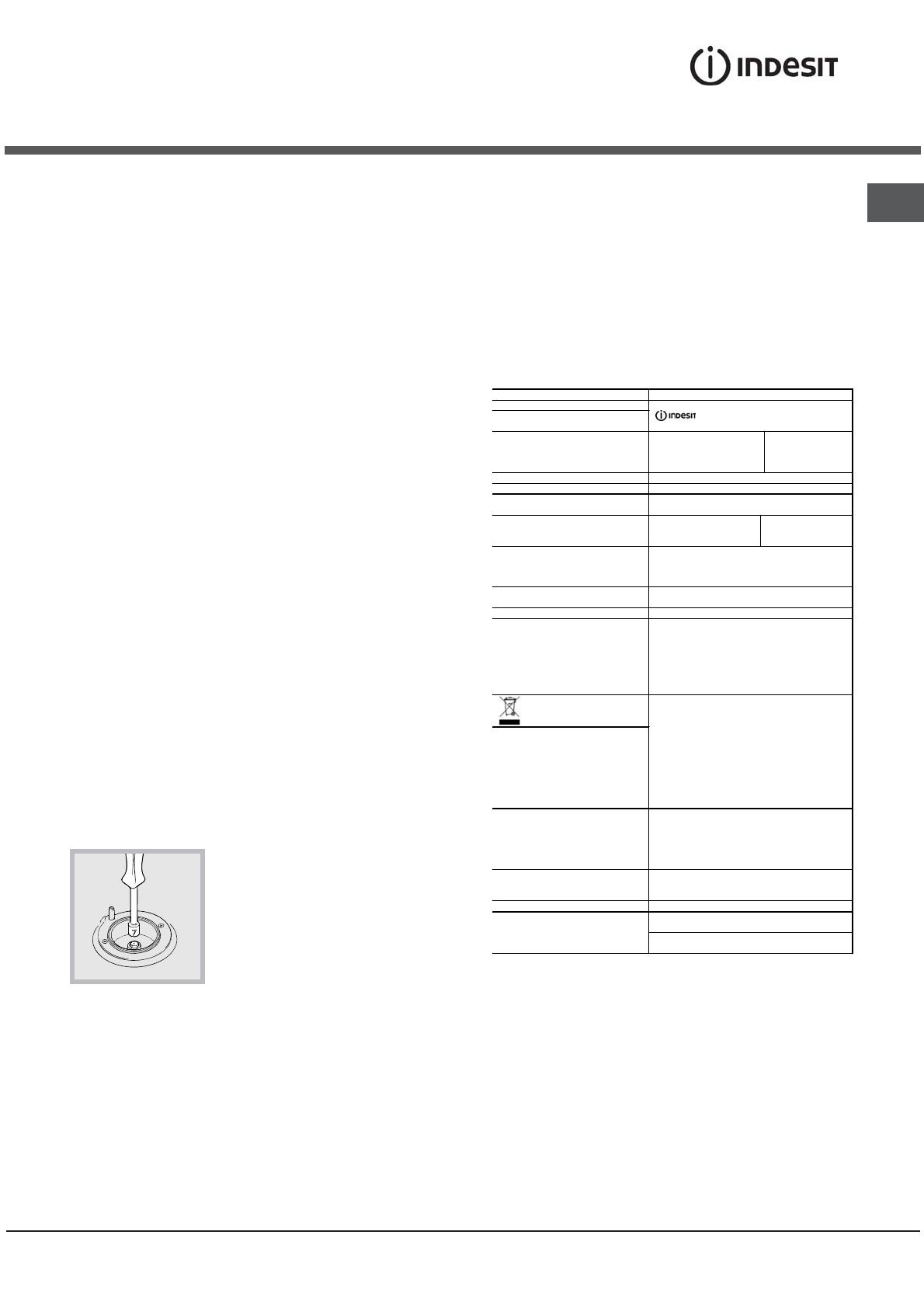
2. отвинтите форсунки при
помощи полого гаечного ключа 7
мм (см. рисунок) и замените их
на форсунки, расчитанные
на
новыи тип газа (см. таблицу
Характеристики горелок и
форсунок);
3. восстановите на место все
комплектующие, выполняя операции в обратном
порядке по отношению к описанным выше.
Порядок регуляции минимального пламени
конфорок на варочнои панели:
1. поверните рукоятку в положение минимального
пламени;
2. снимите рукоятку и поверните регуляционныи винт,
расположенныи внутри или рядом со стержнем крана
,
вплоть до получения стабильного малого пламени.
! В случае использования сжиженного газа винт
регуляции должен быть завинчен до упора.
3. проверьте, чтобы конфорка не гасла при резком
повороте крана из положения максимального
пламени в положение минимального пламени.
! Конфорки варочнои панели не нуждаются в
какои-либо регуляции первичного воздуха.
Рекомендуем прочистить духовой шкаф
перед
началом его эксплуатации, следуя инструкциям,
приведенным в параграфе «Обслуживание и
уход».
.
Электрическая конфорка
Ж 145 мм: 1500 Вт
Ж 180 мм: 2000 Вт
Изделие: Комбинированная плита
Торговая марка:
Торговый знак изго товителя:
Моде ль :
KN3G1/UA
KN3N11S/EU
Изготовитель: Indesit Company
Страна-изготовитель : Польша
Габаритные разм еры духо вого
шкафа / Объем:
34x39x44 см / 58 л
Номинальное значение
напряж ения электропитания или
диапазон напряжения
220-230 V ~ 220-240 V ~
Условное обозначение рода
электрического тока или
номинальная частота переменного
тока
50/60Hz
Класс зашиты от поражения
электрическим током
Класс защиты I
Класс энергопотребления C
ТАБЛИЧКА С ЭЛЕКТРИЧЕСКИМИ
ДАННЫМИ
Директива 2002/40/CE касательно этик еток на
электрических духовках
Норматив EN 50304
Заявление о расходах электроэнергии для
класса на тураль ной конвекции
функция нагревания: Статическое
Директива ЕС: Директива ЕС: 2006/95/EC от
12/12/06 (Низк ое напряж ение) с
последующими изменениями – 2004/108/ЕC
от 15/12/04 (Элек тромагнитная
совместимость) с последующими
изменениями – 2009/142/ЕC от 30/11/09 (Газ) -
90/68/СЕЕ от 22/07/93 с последующим и
изменениями – 2002/96/ЕС.
1275/2008 (Stand-by/ Off mode)
В случае необходимости
получения информации по
сертификатам соответствия или
получения копи й сертификатов
соответствия на данную технику,
Вы можете отправить запрос по
электронному адресу
cert.rus @indes it.com .
Дату производства данной техник и
можно получить из серийного
номера, расположенного под
штри х-кодом (S/N XXXXXXXXX *
XXXXXXXXXXX), следующим
образом:
- 1-ая цифра в S/N соответс твует последней
цифре года,
- 2-ая и 3-я цифры в S/N - порядковому
номеру месяца года,
- 4-ая и 5-ая цифры в S/N - числу
определенного месяца и года.
Производитель:
Indesit Company S.p.A.
Виале А. Мерлони 47, 60044, Фабриано (АН),
Италия
Импортер: ООО "Индезит РУС"
С вопросами (в России)
обращаться по адресу:
до 01.01.2011: Россия, 129223, Моск ва,
Проспект Мир а , ВВЦ, пав. 46
с 01.01.2011: Россия, 127018, Моск ва , ул.
Двинцев, дом 12, корп. 1
18
RS
S
R
ø 145
ø 180
KN3N11S/EU
S
S
R
A
KN3G1/ UA
ВНИМАНИЕ! При нагреве стеклянная
крышка может лопнуть. Прежде чем
закрыть ее, выключить
все конфорки
или электрические горелки.*Только
для моделей со стеклянной крышкой
Характеристики горелок и жиклеров
Сжиженный газ Природный газ
Горелки
Диаметр,
мм
Мощность
нагрева,
кВт (p.c.s.*)
отверстие
1/100
жиклер
1/100
поток*
г/ч
жиклер
1/100
поток*
л/ч
жиклер
1/100
поток*
л/ч
номин. уменьш мм мм
*** **
мм мм
Быстрая (большая) (R) 100 3,00 0,70 41 87 218 214 128 286 143 286
Полубыстрая (средняя) (S) 75 1,90 0,40 30 70 138 136 104 181 118 181
Вспомогательная
(маленькая) (A)
51 1,00 0,40 30 52 73 71 76 95 80 95
Давление
Номинальное (мбар)
Минимальное (мбар)
Максимальное (мбар)
28-30
20
35
37
25
45
20
17
25
13
6,5
18
* Сухой газ при 15 °С и давлении 1013 мбар
** Пропан P.C.S. = 50,37 MДж/кг
*** Бутан P.C.S. = 49,47 MДж/кг
Природный газ P.C.S. = 37,78 MДж/м
3
19
RS
Описание изделия
Панель управления
Общии вид
*
*
Рукоятка
селектора
Рукоятка управления
электроконфоркой*
Рукоятка управления
газовыми конфорками
* Только для некоторых модификаций моделей.
Индикатор
электроконфорки*
Индикатор
термостата
Рукоятка
таймера
Рукоятка
термостата
20
RS
Включение и эксплуатация
Эксплуатация варочной панели
Включение конфорок
Напротив каждого рукоятки КОНФОРКИ
закрашенным кружком показано положение
данной конфорки на варочной панели.
Порядок включения конфорки на варочной панели:
1. поднесите к конфорке зажженую спичку или
кухонную зажигалку;
2. нажмите и одновременно поверните против
часовой стрелки рукоятку КОНФОРКИ на символ
максимального пламени E.
3. отрегулируйте нужную мощность пламени,
поворачивая рукоятку КОНФОРКИ против часовой
стрелки
: на минимум C, на максимум E или на
среднюю мощность.
Если изделие оснащено
электронной системой
зажигания* (C), вначале
нажмите кнопку зажигания,
обозначенную символом
1
, затем нажмите до
упора и одновременно
поверните против часовой стрелки рукоятку
КОНФОРКИ на символ максимального пламени
вплоть до зажигания пламени. Может случиться,
что конфорка погаснет в момент, когда вы
отпустите рукоятку. В этом случае повторите
операцию зажигания, удерживая рукоятку нажатой
подольше.
! В случае внезапного гашения пламени
выключите конфорку и подождите примерно 1
минуту перед
ее повторным включением.
Если изделие оснащено предохранительным
устройством* (X)отсутствия пламени, держите
рукоятку КОНФОРКИ нажатой примерно 2-3
секунды для того, чтобы пламя конфорки
активировало это устройство.
Для выключения конфорки поверните рукоятку
вплоть до гашения пламени
.
Практические советы по эксплуатации
газовых конфорок
Для оптимальной работы конфорок и для экономии
газа следует использовать кухонную посуду с
плоским дном, с диаметром, соответствующим
конфорке, и с крышкой:
Для определения типа конфорки смотрите рисунки в
параграфе «Характеристики конфорок и форсунок».
! В моделях, оснащенных дополнительной
решеткой, эта решетка может быть использована
только на вспомогательной конфорке
с посудой
диаметром меньше 12 см.
Эксплуатация духового шкафа
! При первом включении духового шкафа
рекомендуем прокалить его примерно в течение 30
минут при максимальной температуре с закрытой
дверцей. Затем выключите духовой шкаф, откройте
дверцу и проветрите помещение. Запах, который
вы можете почувствовать, вызван испарением
веществ, использованных для предохранения
духового шкафа.
! Перед началом эксплуатации необходимо снять
пленку, наклеенную с боков изделия.
! Никогда
не ставьте никаких предметов на дно
духового шкафа, так как они могут повредить
эмалированное покрытие. Используйте положение 1
настройки духового шкафа только для
приготовления на вертеле.
Рукоятки управления духовкой
Выбор различных режимов приготовления в
духовке осуществляется с помощью двух
рукояток, расположенных на панели управления:
рукоятки выбора функций духовки;
рукоятки термостатасимвол
(символьные обозначения рукояток
нанесены на
панель управления).
Когда рукоятка выбора функций духовки находится
в любом положении, кроме «0» — выключено, в
духовке горит свет. При установке рукоятки в
позицию
88
88
8
свет зажигается без включения
нагревательных элементов. Горящая лампочка
духовки показывает, что духовка используется.
Свет остается гореть в течение всего времени
использования духовки.
X
C
Горелка Диаметр дна посуды, см
Быстрая (R) 24–26
Полубыстрая (S) 16–20
Вспомогательная (А) 10–14
  • Page 1 1
  • Page 2 2
  • Page 3 3
  • Page 4 4
  • Page 5 5
  • Page 6 6
  • Page 7 7
  • Page 8 8
  • Page 9 9
  • Page 10 10
  • Page 11 11
  • Page 12 12
  • Page 13 13
  • Page 14 14
  • Page 15 15
  • Page 16 16
  • Page 17 17
  • Page 18 18
  • Page 19 19
  • Page 20 20
  • Page 21 21
  • Page 22 22
  • Page 23 23
  • Page 24 24
  • Page 25 25
  • Page 26 26
  • Page 27 27
  • Page 28 28
  • Page 29 29
  • Page 30 30
  • Page 31 31
  • Page 32 32
  • Page 33 33
  • Page 34 34
  • Page 35 35
  • Page 36 36
  • Page 37 37
  • Page 38 38
  • Page 39 39
  • Page 40 40
  • Page 41 41
  • Page 42 42
  • Page 43 43
  • Page 44 44
  • Page 45 45
  • Page 46 46
  • Page 47 47
  • Page 48 48
  • Page 49 49
  • Page 50 50
  • Page 51 51
  • Page 52 52

Indesit KN3G1(X)/UA Руководство пользователя

Категория
Кухонные плиты (варочные панели)
Тип
Руководство пользователя
Это руководство также подходит для

Задайте вопрос, и я найду ответ в документе

Поиск информации в документе стал проще с помощью ИИ