SHORT CIRCUIT PROTECTION | KORTSLUTNINGSBESKYTTE | PROTECCIÓN CONTRA CORTOCIRCUITOS
KURZSCHLUSSSCHUTZ | PROTECTION AU COURT-CIRCUIT | PROTEZIONE DA CORTO CIRCUITO | ЗАЩИТА
ОТ КОРОТКОГО ЗАМЫКАНИЯ | 短路保护
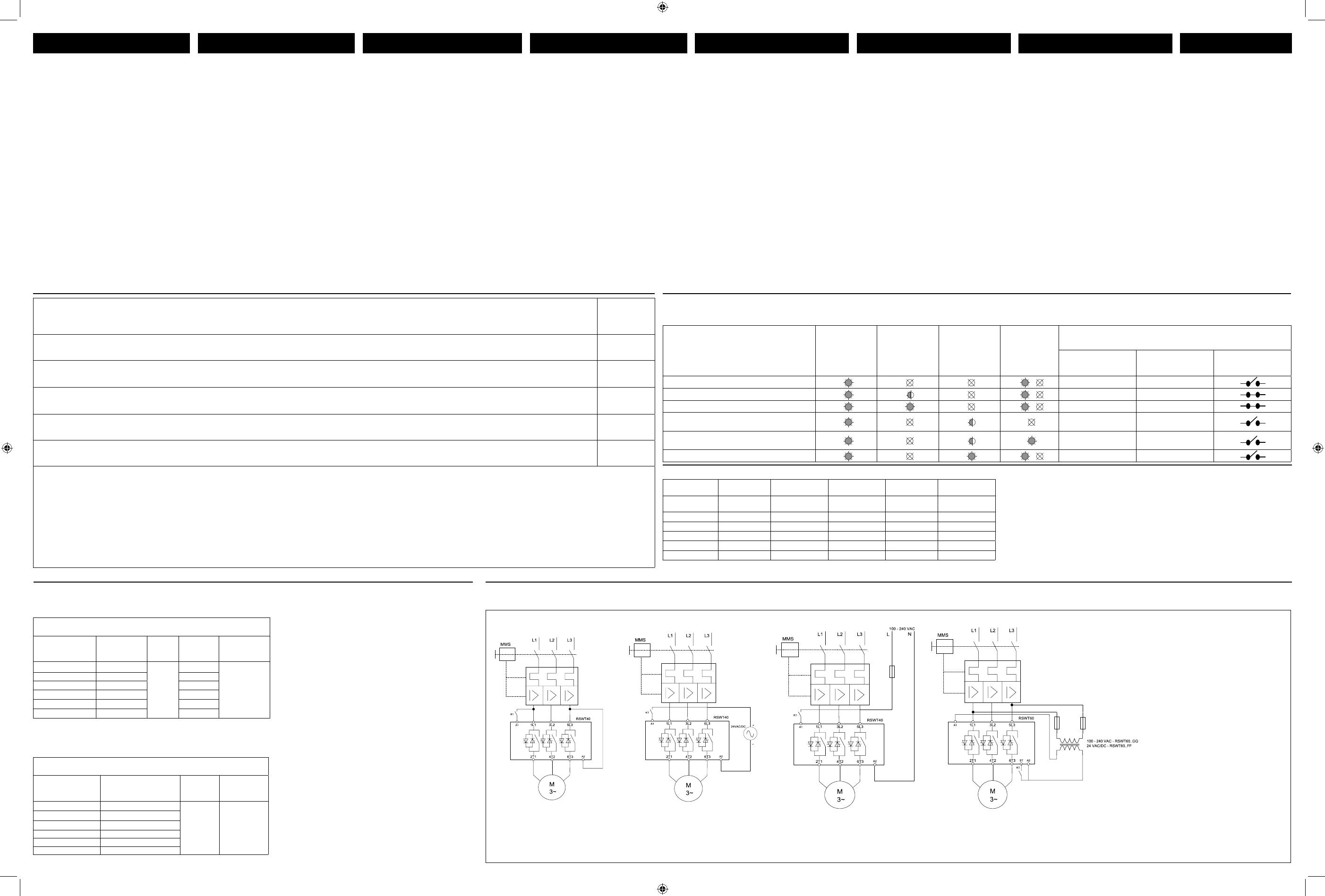
Note: For 24VDC control, A1 should be connected to the (+) terminal and A2 to the (-) terminal. | Примечание: Для напряжения управления 24 В DC A1 подключается на (+), а A2 – на (-). | 注:对于 24 VDC 控制,A1 应连接至 (+) 端子,A2 应连接至 (-) 端子。
CONNECTION DIAGRAM | TILSLUTNINGSDIAGRAMMER | DIAGRAMA DE CONEXIONES | ANSCHLUSSDIAGRAMME | DIAGRAMME DE RACCORDEMENT | DIAGRAMMA DELLE CONNESSIONI | СХЕМА ПОДКЛЮЧЕНИЯ |
连接图
RSWT40...E0V..
RSWT40...F0V..
RSWT40...E0V...
RSWT60..GGV../RSWT60...FFV..
SETTING PROCEDURE INDSTILLINGSPROCEDURE PROCÉDURE DE CONFIGURATION PROCEDURA DI AVVIAMENTO CONFIGURACIÓN
EINSTELLVORGANG
LED INDICATIONS, RELAY CONTACT POSITION | LED, POSITION FOR RELÆKONTAKT | INDICACIONES LED, POSICIÓN DEL CONTACTO DE RELÉ |
LED-ANZEIGEN , POSITION DER RELAISKONTAKTE | INDICATION LED, POSITION DES CONTACTS DE RELAIS | INDICAZIONI LED , POSIZIONE DEI
CONTATTI RELÈ | СВЕТОДИОД ИНДИКАЦИИ, | LED 指示、继电器接触位
State | Состояние | 状态
Green LED (Supply)
Зеленый светодиод
(питание)
绿色 LED(供电)
Yellow LED
(Ramp/Bypass)
Желтый светодиод
(Профиль/Байпас)
黄色 LED(斜坡/旁路)
Red LED (Alarm)
Красный светодиод
(Тревога)
红色 LED(报警)
Yellow LED
(Manual)
Желтый светодиод
(Вручную)
黄色 LED(手动)
Relay Contact Position
Позиция контакта реле
继电器接触位
Alarm |
Тревога
|报警
(11, 12, 14)
Bypass |
Байпас
|旁路
(21, 22, 24)
Run |
Бег
|
跑
(31, 34)
Idle | Без нагрузки | 待机
11, 12 21, 24
Ramping | Профиль | 斜坡
11, 12 21, 24
Bypass | Байпас | 旁路
11, 12 21, 24
Alarm (Auto-recovery) | Тревога (автосброс)
| 报警(自动恢复)
11, 14 21, 22
Alarm (Manual recovery) |
Тревога (ручная активация)
| 报警(手动恢复)
11, 14 21, 22
Internal fault | Внутренняя ошибка | 内部故障
11, 14 21, 22
TYPICAL SETTINGS | TYPISKE INDSTILLINGER | AJUSTES MÁS COMUNES | TYPISCHE EINSTELLUNGEN | PARAMÈTRES TYPIQUES |
IMPOSTAZIONI TIPICHE | ТИПИЧНЫЕ НАСТРОЙКИ | 典型设置
Ramp-up time (s)
Время профиля
(с)
斜升时间(秒)
Hydraulic pump | Hydraulikpumpe | Bomba hidráulica | Hydraulische Pumpe | Pompe hydraulique | Pompa idraulica |
Гидравлический насос | 液压泵
1, 2
Low inertia fan | Ventilator med lav træghed | Ventilador de baja inercia | Lüfter mit niedrigem Trägheitsmoment | Ventilateur
à faible inertie | Ventilatore a bassa inerzia | Вентилятор малой инерции | 低惯量风扇
5, 10
High inertia fan | Ventilator med høj træghed | Ventilador de alta inercia | Lüfter mit hohem Trägheitsmoment | Ventilateur à
haute inertie | Ventilatore ad alta inerzia | Вентилятор большой инерции | 高惯量风扇
15, 20, 30
Centrifugal pump | Centrifugalpumpe | Bomba centrífuga | Zentrifugalpumpe | Pompe centrifuge | Pompa centrifuga |
Центробежный насос | 离心泵
5, 10
Centrifugal blower | Centrifugal blæser | Ventilador centrífugo | Radialgebläse | Soufflante centrifuge | Ventilatore centrifugo |
Центробежная воздуходувка | 离心鼓风机
5, 10
Note: Adjust the knob setting to the FLC value corresponding to the motor name plate to ensure proper overload protection. | Bemærk:
Juster vælgerindstillingen til den FLC-værdi, der svarer til mærkepladen på motoren, for at sikre korrekt beskyttelse mod overbelastning. |
Nota: Colocar el potenciómetro en el valor de FLC correspondiente a la placa de características del motor con el fin de asegurar que la pro-
tección contra sobrecargas es correcta. | Hinweis: Stellen Sie mit dem Drehpotentiometer Vollaststrom (FLC) den maximalen Betriebsstrom
entsprechend dem Motortypenschild ein, um einen ordnungsgemäßen Überlastschutz zu gewährleisten. | Nota: Régler le courant pleine
charge en fonction des caractéristiques de la plaque de firme du moteur/de la pompe afin d’assurer une protection correcte à la surcharge.
| Nota: regolare il selettore FLC sul valore corrispondente al valore di targa riportato sulla targhetta del motore/pompa così da garantire
l’adeguata protezione da sovraccarico. | Примечание: Селектором установите значение тока полной нагрузки в соответствии с
данными электродвигателя для обеспечения надлежащей защиты от перегрузки. | 注:把旋钮设置调节至电机标牌所对应的 FLC
值,以确保适当的过载保护
The RSWT soft starter series feature 3-knob
settings and an additional push button to test
the overload protection, reset the alarms, setting
the alarm recovery to Manual or Auto.
Step 1: Set the ramp-up time: Set the knob
to the desired starting time as required for the
specific application.
Step 2: Set the ramp-down time: Set the knob
to the desired stopping time as required for the
specific application. In this case ramp-down
time can be set to a different value from that
of the ramp-up time. Note: If no soft-stop is
required, set the ramp-down knob to 0 sec.
Step 3: Set the full load current (FLC): Adjust
the knob setting to the FLC value corresponding
to the motor name plate to ensure proper
overload protection.
Step 4: Set the alarm recovery mode: Make
sure the RSWT is in idle mode (Green LED
ON). To set the alarm recovery to auto, press
the Test/Reset button for 5 secs. The MANUAL
LED (yellow LED) will turn OFF. To set the alarm
recovery to MANUAL the same procedure as
described above applies.
Step 5: Test the overload function. To make
sure that the overload function is working
properly press the TEST/RESET button for 1
sec. The RSWT will trip and the red LED will
flash 8 times indicating an overload alarm. The
alarm relay (11,12) will also change state to
Open.
RSWT-softstarter-serien har 3-vælgerindstillinger og en
ekstra trykknap til test af beskyttelse af overbelastning,
nulstilling af alarmer og til indstilling af alarmgenoprettelse
til manuel eller automatisk.
Trin 1: Indstil rampe-op-tidspunktet: Indstil vælgeren til
det starttidspunkt, der ønskes for den pågældende brug.
Trin 2: Indstil rampe-ned-tidspunktet: Indstil vælgeren
til det stoptidspunkt, der ønskes for den pågældende
brug. I dette tilfælde kan rampe-ned-tidspunktet indstilles
til en anden værdi end værdien for rampe-op-tidspunktet.
Bemærk: Hvis der ikke kræves soft-stop, indstilles
rampe-ned-vælgeren fra 0 til 1 sek.
Trin 3: Indstil mærkeeffekt ved fuld belastning (FLC):
Juster vælgerindstillingen til den FLC-værdi, der svarer til
mærkepladen på motoren, for at sikre korrekt beskyttelse
mod overbelastning.
Trin 4: Indstil alarmgenoprettelsestilstand: Sørg
for, at RSWT’en er i idle-tilstand (grøn LED TIL).
Alarmgenoprettelse sættes til automatisk ved at trykke
på knappen Test/Reset (test/nulstil) i mindst 5 sekunder.
MANUEL LED (gul LED) vil slå FRA, hvilket indikerer, at
alarmerne vil følge en automatisk rutine for genoprettelse.
Alarmgenoprettelse sættes til MANUEL på samme måde
som beskrevet herover Bemærk: Standardindstillingen
i RSWT er auto alarmgenoprettelse (gul LED MANUEL
OFF)
Trin 5: Test overbelastningsfunktionen Tryk på
knappen TEST/RESET (test/nulstil) i cirka 1 sek. for
at kontrollere, at overbelastningsfunktionen fungerer
korrekt. RSWT’en vil koble ud, og den røde LED vil
blinke 8 gange for at indikere en overbelastningsalarm.
Alarmrelæ (11,12) vil også ændre status til Åben.
Les démarreurs progressifs de la série RSWT
comportent 3 boutons de réglage ; le bouton poussoir
complémentaire permet de tester la protection
à la surcharge, d’acquitter les alarmes et de régler
l’acquittement manuel ou automatique des alarmes.
Étape 1 – Bouton de réglage du temps d’accélération.
Régler le temps de démarrage souhaité en fonction de
l’application particulière.
Étape 2 – Bouton de réglage du temps de décélération.
Régler le temps d’arrêt souhaité en fonction de
l’application particulière. Dans ce cas, on peut régler
le temps de décélération à une valeur différente du
temps d’accélération. Nota : si l’arrêt progressif n’est
pas requis, régler le temps de décélération à 0 s avec le
bouton de réglage.
Étape 3 – Bouton de réglage du courant pleine charge
(FLC). Régler le courant pleine charge en fonction des
caractéristiques de la plaque de firme du moteur afin
d’assurer une protection correcte à la surcharge.
Étape 4 – Réglage du mode d’acquittement de
l’alarme. Constater que le RSWT est au repos (LED
verte allumée). Pour régler l’acquittement automatique
de l’alarme, appuyer sur le bouton Test/Acquittement
pendant 5s. En s’éteignant, la LED jaune (MANUEL)
indique que l’acquittement des alarmes est un processus
automatique. Pour régler l’acquittement des alarmes en
mode manuel, la procédure est identique à celle décrite
plus haut. Nota: Par défaut, l’acquittement des alarmes
du RSWT est réglé en manuel (LED jaune MANUAL
OFF).
Étape 5 – Test de la fonction de surcharge. Appuyer
sur la touche Test/Acquittement pendant 1 s environ et
constater le bon fonctionnement de la protection à la
surcharge. En cas de surcharge, le RSWT déclenche et
la LED rouge clignote huit (8) fois, signalant une condition
de surcharge. L’état du relais d’alarme (11,12) change
(ouverture).
ENGLISH DANSK ESPAÑOL DEUTSCH FRANCAIS ITALIANO
Die Motor-Softstarterserie RSWT besitzt drei
Drehknöpfe und einen zusätzlichen Drucktaster. Damit
kann der Überlastschutzes geprüft, die Alarmmeldungen
zurückgesetzt und die Alarmeinstellung auf manuellen
oder automatischen Alarm gesetzt werden. Weiterhin
kann damit der Phasenfolgefehler Alarm aktivieren /
deaktivieren werden.
Schritt 1: Einstellen der Anlaufzeit: Stellen Sie mit
dem Drehknopf die für die jeweilige Anwendung
erforderliche Startzeit ein.
Schritt 2: Einstellen der Auslaufzeit: Stellen Sie mit
dem Drehknopf die für die jeweilige Anwendung
erforderliche Stoppzeit ein. In diesem Fall kann die
Auslaufzeit auf einen von der Anlaufzeit abweichenden
Wert eingestellt werden. Hinweis: Wenn kein
Sanftauslauf erforderlich ist, stellen Sie den Knopf für
die Auslaufzeit auf 0 s ein.
Schritt 3: Einstellen des Volllaststroms (FLC): Stellen
Sie mit dem Drehknopf den FLC-Wert entsprechend
dem Motortypenschild ein, um einen ordnungsgemäße
Überlastschutz zu gewährleisten.
Schritt 4: Einstellen des Alarmwiederherstellungsmodus:
Vergewissern Sie sich, dass sich das RSWT im
Standby- Modus befindet (grüne LED EIN). Drücken
Sie, um die Alarmeinstellung auf automatisch zu
stellen, die Prüf-/ Rücksetztaste mindestens 5 s.
Die LED für manuelle Alarmrücksetzen (gelbe LED)
erlischt. Dies zeigt an, dass die Alarmeinstellung
auf automatisch eingestellt ist. Um die manuelle
Alarmrücksetzen einzustellen, verfahren Sie in der
gleichen Weise wie oben angegeben.
Schritt 5: Prüfung der Überlastfunktion. Drücken
Sie die Prüf-/ Rücksetztaste etwa 1 s lang, um zu
überprüfen, ob die Überlastfunktion einwandfrei
arbeitet. Das RSWT löst aus und die rote LED blinkt
8 Mal zur Anzeige eines Überlastalarms. Gleichzeitig
öffnet des Alarmrelais (11,12).
La serie RSWT de arrancadores suaves tiene 3
potenciómetros de ajuste y un pulsador adicional para
comprobar la protección contra sobrecargas, poner a
cero las alarmas y configurar la recuperación de alarmas
en modo Manual o Automático.
Paso 1: Ajuste del tiempo de rampa ascendente.
Colocar el potenciómetro en el tiempo de arranque
deseado para la aplicación en cuestión.
Paso 2: Ajuste del tiempo de rampa descendente.
Colocar el potenciómetro en el tiempo de parada
deseado para la aplicación en cuestión. En este caso
el tiempo de rampa descendente debe tener un valor
diferente al de la rampa ascendente.Nota: Si no es
necesaria la parada suave, poner el potenciómetro de
rampa descendente a 0 seg.
Paso 3: Ajuste de la intensidad a plena carga
(FLC). Colocar el potenciómetro en el valor de FLC
correspondiente a la placa de características del
motor con el fin de asegurar que la protección contra
sobrecargas es correcta.
Paso 4: Ajuste del modo de recuperación de alarmas.
Asegurar que RSWT está en estado de reposo (LED
verde encendido). Para establecer la recuperación de
las alarmas en AUTO, pulsar el botón de Prueba/Puesta
a cero durante un mínimo de 5 seg. El LED MANUAL
(LED amarillo) se apagará indicando que las alarmas
seguirán una rutina automática de recuperación. Para
poner la recuperación de las alarmas en MANUAL seguir
el mismo procedimiento que el arriba indicado.
Paso 5: Comprobación de la función de protección
contra sobrecargas: Para asegurar que la función de
protección contra sobrecargas funciona correctamente
pulsar el botón PRUEBA/PUESTA A CERO durante
aproximadamente 1 segundo. RSWT se disparará y
el LED rojo parpadeará 8 veces indicando una alarma
de sobrecarga. El relé de alarma (11,12) cambiará su
estado a Abierto.
I soft starter della serie RSWT sono caratterizzati da 3
selettori di regolazione e da un pulsante per effettuare
il test della protezione da sovracorrente, resettare
gli allarmi, programmare il ripristino degli allarmi da
manuale ad automatico.
Fase 1: set del tempo della rampa di avvio.
Posizionare il selettore scegliendo il tempo in funzione
della specifica applicazione.
Fase 2: set del tempo della rampa di decelerazione.
Posizionare il selettore scegliendo il tempo in funzione
della specifica applicazione. Nota: se non è richiesta
una rampa di decelerazione, posizionare il selettore
a 0 sec.
Fase 3: set della massima corrente di carico (FLC).
Posizionare il selettore in accordo con il valore di
corrente max. riportato sulla targhetta del motore così
da garantire la corretta protezione da sovracorrente.
Fase 4: set della modalità di ripristino allarme.
Assicurarsi che l’RSWT sia inattivo (led VERDE
ON). Per impostare il ripristino dell’allarme in modo
automatico, tenere premuto il pulsante Test/Reset
per 5 sec. L’indicatore luminoso MANUALE (led
GIALLO) si spegnerà. Per impostare nuovamente la
modalità di ripristino allarme su MANUALE, seguire
la procedura sopra descritta.
Fase 5: verifica della funzione di sovracorrente. Per
verificare il corretto funzionamento della funzione di
sovracorrente, premere il pulsante di TEST / RESET
per 1 sec. L’ RSWT effettuerà una simulazione e il led
ROSSO lampeggerà per 8 volte indicando l’allarme
di sovracorrente. I contatti del relè di uscita allarme
(11,12) cambieranno il loro stato e risulteranno
aperti.
ПРОЦЕДУРА НАСТРЙОКИ
РУССО
УПП RSWT имеют 3 рукоятки настройки и
дополнительную кнопку для контроля защиты
от перегрузки, сброса тревоги, задания режима
сброса Manual или Auto и подключения/ отключения
защиты от неправильного чередования фаз.
Шаг 1: задайте время профиля разгона:
Установите рукоятку в положение времени пуска,
соответствующего данному применению.
Шаг 2: задайте время профиля останова:
Установите рукоятку в положение времени
останова, соответствующего данному применению.
В этом случае профиль останова может быть
задан отличным от времени профиля разгона.
Примечание: Если плавный останов не нужен,
установите рукоятку времени профиля останова
в позицию 0 с.
Шаг 3: Задайте ток полной нагрузки (FLC):
Установите рукоятку на значение FLC,
соответствующее данным двигателя, для
надлежащей защиты от перегрузки.
Шаг 4: Задайте режим сброса тревоги:
Убедитесь, что RSWT без нагрузки (зеленый
светодиод ВКЛ.). Для задания автоматического
режима сброса нажмите и удерживайте кнопку
Test/Reset в течение 5 с. Светодиод MANUAL
(желтый) изменит состояние на ВЫКЛ. Для
задания ручного режима процедура аналогична
вышеописанной.
Шаг 5: Тестирование защиты от перегрузки
Нажмите и удерживайте кнопку TEST/RESET в
течение 1 с. RSWT отключится по защите, красный
светодиод даст 8 вспышек для индикации тревоги
по перегрузке. Тревожный контакт выходного реле
(11,12,14) перейдет в разомкнутое состояние.
设置步骤
简体中文
RSWT 软启动器系列的主要特征是
三个旋钮设定和一个额外按钮,以
测试过载保护、将报警复位、将报
警恢复设定为“手动”或“自动”
以及启用/禁用相序保护。
第 1 步:设置斜升时间:将该旋
钮设置到具体应用所需的启动时
间。
第 2 步:设置斜降时间:将该旋
钮设置到具体应用所需的停止时
间。在这种情况下,斜降时间的设
定值可与斜升时间的设定值不同。
注:如果不需要软停止,则将斜降
旋钮设置为 0 秒。
第 3 步:设置满载电流 (FLC):把
旋钮设置调节至电机标牌所对应的
FLC 值,以确保适当的过载保护
第 4 步:设置报警恢复模式:确
保 RSWT 处于待机模式(绿色 LED
亮)。要将报警恢复设定为“自
动”,请按下“测试/复位”按钮
5 秒。“手动 LED”(黄色 LED)
将熄灭。将报警恢复设定为“手
动”的步骤同上。
第 5 步:测试过载功能。要确保
过载功能正常工作,请按“测试/
复位”按钮 1 秒。RSWT 将脱扣,
且红色 LED 将闪烁 8 次,指示过
载报警。报警继电器(11、12)的
状态也会变为“开”。
Coordination Type 1 (UL508) – Time Delay Fuses | Тип 1 (UL508) –
Предохранители затяжного срабатывания | 一类配合 (UL508) – 延时熔断器
Part No.
номер части
零件号
Max. Fuse Size [A]
Макс. Номинал
предохранителя [A]
熔断器最大规格 [A]
Class
Класс
类
Current [kA]
Ток [кA]
电流 [kA]
Max. Voltage [VAC]
Макс. напряжение
[В AC]
最大电压 [VAC]
RSWT..32.V…. 60
RK5
5
600
RSWT..37.V…. 60 5
RSWT..45.V…. 60
5
RSWT..55.V…. 60 5
RSWT..70.V…. 100 10
RSWT..90.V…. 100 10
Co-ordination Type 1 - Manual Motor Starters | Тип 1 – Ручные пускатели
| 一类配合 - 手动电机启动器
Part No.
номер части
零件号
MMS Model No. *
MMS модель Np. *
MMS 型号*
Current [kA]
Ток [кA]
电流 [kA]
Max. Voltage [VAC]
Макс. напряжение
[В AC]
最大电压 [VAC]
RSWT..32.V…. GMS63H-32A
10 400
RSWT..37.V…. GMS63H-40A
RSWT..45.V…. GMS63H-50A
RSWT..55.V…. GMS63H-63A
RSWT..70.V…. GMS100S-75A
RSWT..90.V…. GMS100S-100A
CURRENT / POWER RATINGS @ 40˚C | НОМИНАЛЬНЫЙ ТОК/МОЩНОСТЬ ПРИ 40ºC | 40ºC 下的电流/功率额定值
Model
IEC Rated
Current
220 - 240 VAC 380 - 415 VAC
440 - 480
VAC
550 - 600 VAC
RSWT..32.V…. 32 AAC 9 kW/ 10 HP 15 kW/ 20 HP
18.5 kW/ 20
HP
22 kW/ 30 HP
RSWT..37.V…. 37 AAC 9 kW/ 10 HP 20 kW / 25 HP 22 kW / 30 HP 30 kW/ 30 HP
RSWT..45.V…. 45 AAC 11 kW/ 15 HP 22 kW / 30 HP 22 kW / 30 HP 37 kW / 40 HP
RSWT..55.V…. 55 AAC 15 kW/ 20 HP 30 kW/ 30 HP 30 kW/ 30 HP 45 kW / 50 HP
RSWT..70.V…. 70 AAC 20 kW / 25 HP 37 kW / 40 HP 45 kW / 50 HP 55 kW / 60 HP
RSWT..90.V…. 90 AAC 22 kW / 30 HP 45 kW / 50 HP 55 kW / 60 HP 75 kW / 75 HP
* Note: Products protected with manual motor starters must be wired with a minimum length
of 2m of Cu wire conductor with a maximum cross-sectional area of 16 mm
2
for 32 A - 55 A
devices and 50mm
2
for higher currents. The length includes the conductors from the voltage
source to the manual motor starter to the soft starter and from the soft starter to the load.
* Bemærk:
Produkter, der er beskyttet med manuelle motorstartere skal tilsluttes med en længde på mindst 2 m Cu wire.
For produkter med 32 A - 55 A skal det maksimale tværsnitsareal være på 16mm
2
, for produkter med 70, 85,
100A skal maksimum tværsnitsareal være af 50mm
2
.Længden inkluderer ledere fra spændingskilden til den
manuelle motorstarter, fra denmanuelle motorstarter til softstarteren og fra softstarteren til belastningen.
* Nota: Los productos protegidos con arrancadores manuales deben utilizar un cable de
cobre de al menos 2m de longitud, con una sección mínima de 16mm
2
para los equipos
de 32 A - 55 A y de 50mm
2
para corrientes más altas. La longitud incluye conducto-
res desde la toma de tensión de la protección al arrancador y del arrancador a la carga.
* Hinweis: Die Produkte, die über einen Motorschutzschalter geschützt werden, müssen mit einer
Mindestleitungslänge von 2 m angeschlossen werden und mit einer max. Leitungsquerschnitten
von 16mm
2
für 32 A - 55 A Typen und 50mm
2
für höhere Ströme. Die Länge umfasst die Leitung
von der Spannungsquelle zur Motorschutzschalter, Softstarter und bis zum Softstarter zur Last.
* Nota: Les produits protégés par un démarrage manuel doivent être câblés avec un conduc-
teur Cu d’une longueur minimum de 2m. Pour le produit 32 A - 55 A, la section de câble maxi
doit être de 16mm², pour les produits 70, 90 A, la section de câble maxi doit être de 50mm².
Les longueurs indiquées pour les conducteurs s’entendent de la source de tension au démarreur
manuel, du démarreur manuel au démarreur progressif et du démarreur progressif à la charge.
* Nota: I prodotti protetti con salvamotori, devono essere cablati con cavo in rame della
lunghezza minima di 2m. Per i dispositivi con corrente nominale di 32 A - 55 A la sezi-
one massima del cavo dovrà essere di 16mm² , per quelli con corrente nominale di 70 A e
90 A la sezione massima dovrà essere di 50mm². La lunghezza include i conduttori dalla
linea di alimentazione al salvamotore, dal salvamotore al soft start e dal soft start al motore.
* Примечание: электромонтаж УПП, защищенных ручными прерывателями, осуществляется
медным проводником длиной не менее 2,0м с максимальным сечением 16 мм
2
для УПП током
32 A - 55 A и 50 мм
2
для УПП с более высоким током. Длина включает проводник
от источника тока от ручного прерывателя до УПП и от УПП до нагрузки.
*注:用手动电机启动器保护的产品必须连接最小长度 2,0 m 的铜导线,32 A - 55A 设备对
应的最大横截面积为 16 mm
2
,更高电流对应的最大横截面积为 50 mm
2
。该长度包括从电
压源至手动电机启动器、从手动电机启动器至软启动器、从软启动器至负载之间的导线。
Overload Protection (UL 508)
This equipment provides motor overload protection at 120% of FLA. (Full Load Amps)
Protection contre la surcharge (UL 508)
Ce produit intègre une protection contre la surcharge à 120% du courant de pleine charge.
Note: Note: For RSWT60..GG models apply: 100 - 240VAC across
A1 - A2 terminals. For RSWT60..FF models apply: 24VAC/DC
across A1 - A2 terminals.
Bemærk: Ved RSWT60..GG-modeller anvendes 100 - 240 VAC til
A1-, A2- klemmer. Ved RSWT60..FF-modeller anvendes 24 VAC/DC
til A1-, A2-klemmer.
Nota: En los modelos RSWT60..GG se aplica 100-240 VCA a través
de los terminales A1, A2. En los modelos RSWT60..FF se aplica 24
VCA/CC a través de los terminales A1, A2.
Hinweis: Bei den Modellen RSWT60..GG werden 100 – 240 VAC
an den Klemmen A1, A2 angelegt. Bei den Modellen RSWT60..FF
werden 24 VAC/DC an den Klemmen A1, A2 angelegt.
Nota: Types RSWT60..GG: appliquer une tension de 100 - 240 Vca
aux bornes A1, A2. Types RSWT60..FF: appliquer une tension de
24 Vca/cc aux bornes A1, A2.
Nota: per la versione RSWT60..GG applicare 100-240 VCA sui
terminali A1,A2. Per la versione RSWT60..FF applicare 240 VCC/CA
sui terminali A1,A2.
Примечание: Для моделей RSWT60..GG: 100 – 240 В AC на
клеммах A1 - A2. Для моделей RSWT60..FF: 24 B DC/AC на
клеммах A1 - A2.
注:对于 RSWT60..GG 型:A1 - A2 端子上应为 100
- 240VAC。对于 RSWT60..FF 型:A1 - A2 端子上应为
24VAC/DC。

