6
Importantes Instrucciones de Seguridad
Este manual contiene información concerniente a la instalación y uso apropiados de las barras
de contacto para montaje en bastidor de Tripp Lite.
GUARDE ESTAS INSTRUCCIONES.
No conecte la regleta de contactos a una toma de corriente que no tenga conexión a tierra.
No la use con cables de extensión o adaptadores que eliminen la conexión a tierra. La regleta de contactos
está diseñada exclusivamente para uso en interiores. Instálela alejada de dispositivos que emitan calor tales
como radiadores y rejillas de calefacción. No la instale donde haya humedad excesiva, ni cualquier otro tipo
de contaminante conductivo. Nunca instale un cableado eléctrico durante tormentas eléctricas.
Los requerimientos de energía eléctrica de cada dispositivo conectado a una toma de corriente de la regleta
de contactos, no deberá exceder el valor nominal de potencia de salida de la regleta de contactos (refiérase a
la Ficha técnica). Los requerimientos totales de energía eléctrica de todos los dispositivos conectados a la
toma de corriente de la regleta de contactos no deberán exceder el valor nominal de carga máxima de la
regleta de contactos (refiérase a la Ficha técnica).
PRECAUCION Este aparato no se destina para utilizarse por personas (incluyendo niños), cuyas
capacidades fisicas, sensoriales o mentales sean diferentes o estén reducidas, o carezcan de experiencia o
conocimiento, a menos que dichas personas reciban una supervisión o capacitación para el funcionamiento del
aparato por una persona responsable de su seguridad.
Los ninos deben de supervisarse para asegurar que no empleen el aparato como juguete.
Nunca utilize el aparato si el cable y la clavija están dañados; si no funciona correctamente o si se ha caido o
dañado, llévelo a un centro de servicio autorizado para que lo examinen y lo reparen.
Si el cordon de alimentación es dañado, éste debe sustituirse por el fabricante, por su agente de servicio
autorizado o por personal calificado con el fin de evitar un peligro.
Instalación
Instalación para montaje en
bastidor del modelo 1U
Instalación para montaje
en bastidor del modelo 0U
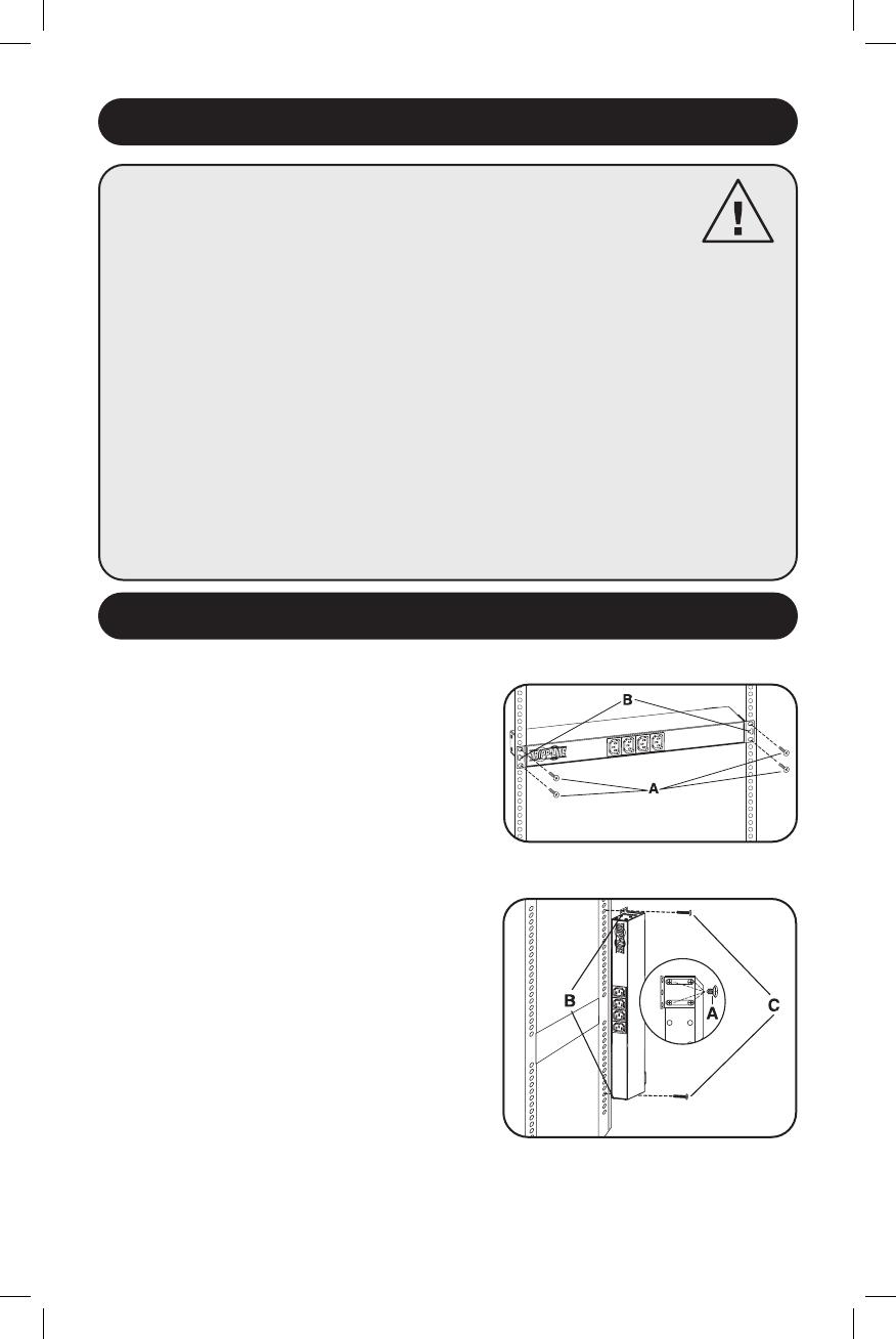
Instalación para montaje en bastidor del modelo 1U
Para realizar el montaje de la unidad en un
bastidor: Introduzca cuatro tornillos para montaje en
bastidor (A), proporcionados por el usuario, a través
de las lengüetas de montaje (B) y dentro de los rieles
del bastidor tal como se muestra. El usuario debe
determinar si los tornillos para montaje en bastidor
son adecuados para sostener la unidad antes de
realizar la instalación.
Instalación para montaje en bastidor del modelo 0U
1. Reoriente las lengüetas de montaje: Retire los
tornillos (A) que sostienen las lengüetas de la
unidad (B) a ambos lados de ésta. Utilice los
tornillos (A) del Paso 1 para volver a unir las
lengüetas de montaje (B) a la unidad tal como se
muestra. Utilice únicamente los tornillos
suministrador por el fabricante u otros equivalentes
(#6-32, de cabeza plana de 1/4”), para volver a
unir las lengüetas de montaje.
2. Realice el montaje de la unidad fuera de los
rieles del bastidor: Ponga cuatro tornillos (C),
proporcionados por el usuario u otro equipo de
montaje similar, a través de las lengüetas de
montaje (B) y en la sección lateral del bastidor tal
como se muestra. El usuario debe determinar si el
equipo de montaje utilizado es adecuado para
soportar la unidad antes de realizar el montaje.
Paso 1
21-03-410-933401.indb 621-03-410-933401.indb 6 4/1/2021 2:51:57 PM4/1/2021 2:51:57 PM


