HOTPOINT/ARISTON 7OFH G (WH) RU/HA Руководство пользователя
- Категория
- Печи
- Тип
- Руководство пользователя
Это руководство также подходит для

7OFH G RU/HA
7OFH G IX RU/HA
7OFHRG RU/HA
GOS 7 A RFH
GOS 7 I RFH
English
Operating Instructions
OVEN
Contents
Operating Instructions,1
Warnings,2
Assistance,4
Description of the appliance,5
Description of the appliance,6
Installation,7
Start-up and use,11
Cooking modes,12
Precautions and tips,14
Maintenance and care,14
Русскии
Руководство по эксплуатации
ДУХОВОЙ ШКАФ
Содержание
Руководство по эксплуатации,1
Предупреждения,2
Сервисное обслуживание,4
Описание изделия,5
Описание изделия,6
Установка,16
Включение и эксплуатация,20
Программы,22
Предосторожности и рекомендации,23
Техническое обслуживание и уход,24
Қазақша
Пайдалану нұсқаулығы
ПЕШ
Мазмұны
Пайдалану нұсқаулығы,1
Ескертулер,3
Көмек,4
Құрылғы сипаттамасы,5
Құрылғы сипаттамасы,6
Орнату,25
Қосу және пайдалану,28
Тағам дайындау режимдері,29
Сақтандырулар мен кеңестер,32
Күтім және пайдалану,32

2
Warnings
WARNING: The appliance and its
accessible parts become hot during use.
Care should be taken to avoid touching
heating elements. Children less than 8
years of age shall be kept away unless
continuously supervised. This appliance
can be used by children aged from 8 years
and above and persons with reduced
physical, sensory or mental capabilities
or lack of experience and knowledge
if they have been given supervision
or instruction concerning use of the
appliance in a safe way and understand
the hazards involved. Children shall not
play with the appliance. Cleaning and
user maintenance shall not be made by
children without supervision.
Do not use harsh abrasive cleaners or
sharp metal scrapers to clean the oven door
glass since they can scratch the surface,
which may result in shattering of the glass.
Never use steam cleaners or pressure
cleaners on the appliance.
WARNING: Ensure that the appliance is
switched off before replacing the lamp to
avoid the possibility of electric shock.
! When you place the rack inside, make
sure that the stop is directed upwards and
in the back of the cavity.
Предупреждения
ВНИМАНИЕ: Данное изделие и его
доступные комплектующие сильно
нагреваются в процессе эксплуатации.
Будьте осторожны и не касайтесь
нагревательных элементов.
Не разрешайте детям младше 8 лет
приближаться к изделию без контроля.
Данное изделие может быть
использовано детьми старше 8 лет и
лицами с ограниченными физическими,
сенсорными или умственными
способностями или без опыта и знания
о правилах использования изделия при
условии надлежащего контроля или
обучения безопасному использованию
изделия с учетом соответствующих
рисков. Не разрешайте детям играть
с изделием. Не разрешайте детям
осуществлять чистку и уход за
изделием без контроля взрослых.
Не используйте абразивные вещества
или режущие металлические скребки
для чистки стеклянной дверцы духового
шкафа, так как они могут поцарапать
поверхность, что может привести к
разбиванию стекла.
Никогда не используйте паровые
чистящие агрегаты или агрегаты под
высоким давлением для чистки изделия.
ВНИМАНИЕ: Проверьте, чтобы изделие
было выключено, перед заменой
лампочки во избежание возможных
ударов током.
! При установке решетки проверить,
чтобы фиксатор был повернут вверх
с задней стороны выемки.

3
Ескертулер
ЕСКЕРТУ: Құрылғы мен оның қол
жететін бөліктері жұмыс кезінде қызуы
мүмкін.
Қыздыру элементтеріне тимеуге назар
аударыңыз.
8-ге толмаған балаларға үздіксіз
бақылау болмаса, құрылғыдан аулақ
ұстау керек. Бұл құрылғыны қауіпсіз
түрде қолдану бойынша кеңес не
нұсқау берілген және ықтимал қауіп-
қатерлерді түсінетін жағдайда, оны 8-ге
толған балалар мен дене, сезіну немесе
ой қабілеті төмен немесе тәжірибесі
мен білімі жеткіліксіз адамдар қолдана
алады. Балаларға құрылғымен ойнауға
болмайды. Балаларға бақылаусыз
құрылғыны тазалауға және оған қызмет
көрсетуге болмайды.
Пеш есігінің шынысын тазалау үшін қатты
ысқыш тазалағыштарды немесе өткір
метал ысқыщтарды пайдаланбаңыз,
себебі олар шыныны сызып, оның
шағылуына әкелуі мүмкін.
Құрылғыда ешқашан бу тазартқышты
немесе шаңсорғышты пайдаланбаңыз.
ЕСКЕРТУ: Тоқ соғу мүмкіндігінің алдын
алу үшін шамды ауыстырмас бұрын
құрылғы өшірілгеніне көз жеткізіңіз.
! Тартпаны ішке салған кезде шектегіш
жоғары қарап, қуыстың артқы жағында
тұрғанына көз жеткізіңіз.

4
Assistance
! Never use the services of an unauthorised technician.
Please have the following information to hand:
• The type of problem encountered.
• The appliance model (Mod.).
• The serial number (S/N).
The latter two pieces of information can be found on the
data plate located on the appliance.
Сервисное обслуживание
! Никогда не обращайтесь к неуполномоченным
техникам.
При обращении в Центр Технического обслуживания
сообщите:
• Тип неисправности;
• Модель изделия (Мод.)
• Номер тех. паспорта (серийный №)
Эти данные вы найдете на паспортной табличке,
расположенной на изделии.
Көмек
! Рұқсаты жоқ адамның қызметін ешқашан қабылдамаңыз.
Келесі мәліметтерді оңай жерде ұстаңыз:
• Туындаған проблема түрі.
• Құрылғының моделі (Мод.).
• Сериялық нөмірі (С/н).
Кейінірек мәліметтердің екі бөлігін құрылғының деректер
тақтасынан көре аласыз.

5
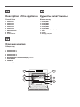
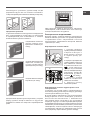
Description of the appliance
Overall view
1 POSITION 1
2 POSITION 2
3 POSITION 3
4 POSITION 4
5 POSITION 5
6 GUIDES for the sliding racks
7 DRIPPING PAN
8 GRILL
9 Control panel
Описание изделия
Общии вид
1 ПОЛОЖЕНИЕ 1
2 ПОЛОЖЕНИЕ 2
3 ПОЛОЖЕНИЕ 3
4 ПОЛОЖЕНИЕ 4
5 ПОЛОЖЕНИЕ 5
6 ВЫДВИЖНЫЕ НАПРАВЛЯЮЩИЕ уровней
7 ПРОТИВЕНЬ
8 РЕШЕТКА
9 Панель управления
Құрылғы сипаттамасы
Жалпы шолу
1 ПОЗИЦИЯ 1
2 ПОЗИЦИЯ 2
3 ПОЗИЦИЯ 3
4 ПОЗИЦИЯ 4
5 ПОЗИЦИЯ 5
6 Сырғымалы серелерге арналған СЫРRЫТПАЛАР
7 ТАБА
8 ГРИЛЬ
9 Басқару тaқтaы
7
8
9 6
1
2
3
4
5

6
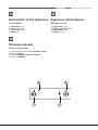
Description of the appliance
Control panel
1 OVEN/GRILL knob
2 GRILL indicator light
3 OVEN LIGHT button
4 TIMER knob
Описание изделия
Панель управления
1 Рукоятка-переключатель режима ДУХОВКА / ГРИЛЬ
2 Индикатор ГРИЛЬ
3 Кнопка ОСВЕЩЕНИЕ ДУХОВОГО ШКАФА
4 Регулятор ТАЙМЕРА
Құрылғы сипаттамасы
Басқару тaқтaы
1 ПЕШ/ГРИЛЬ тұтқacы
2 ГРИЛЬ индикатор шамы
3 ПЕШ ШАМЫ туймесi
4 ТАЙМЕР тұтқacы
1
2
3
4
Min
Max
150
180
220
0
1
0

GB
7
Installation
! Please keep this instruction booklet in a safe place for
future reference. If the appliance is sold, given away or
moved, please make sure the booklet is also passed on to
the new owners so that they may benet from the advice
contained within it.
! Please read this instruction manual carefully: it contains
important information concerning the safe operation,
installation and maintenance of the appliance.
Positioning
! Do not let children play with the packaging material; it
should be disposed of in accordance with local separated
waste collection standards (see Precautions and tips).
! The appliance must be installed by a qualied professional in
accordance with the instructions provided. Incorrect installation
may damage property or cause harm to people or animals.
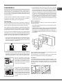
! This unit may be installed and used only in permanently
ventilated rooms in accordance with British Standard Codes Of
Practice: B.S. 6172 / B.S. 5440, Par. 2 and B.S. 6891 Current
Editions. The following requirements must be observed:
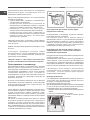
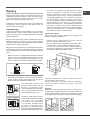
• The room must be equipped with an air extraction system
that expels any combustion fumes. This may consist of
a hood or an electric fan that automatically starts each
time the appliance is switched on.
In a chimney stack or branched flue.
(exclusively for cooking appliances)
Directly to
the Outside
• The room must also allow proper air circulation, as air is
needed for combustion to occur normally. The ow of air
must not be less than 2 m
3
/h per kW of installed power.
The air circulation system may
take air directly from the outside
by means of a pipe with an inner
cross section of at least 100 cm
2
;
the opening must not be vulnerable
to any type of blockages.
The system can also provide the air
needed for combustion indirectly,
i.e. from adjacent rooms tted with
air circulation tubes as described
above. However, these rooms must
not be communal rooms, bedrooms
or rooms that may present a re
hazard.
A
Examples of
ventilation holes
for comburant air.
Enlarging the ventilation slot
between window and floor.
Adjacent
Room
Room to be
Vented
• Liquid petroleum gas sinks to the oor as it is heavier
than air. Therefore, rooms containing LPG cylinders must
also be equipped with vents to allow gas to escape in
the event of a leak. As a result LPG cylinders, whether
partially or completely full, must not be installed or stored
in rooms or storage areas that are below ground level
(cellars, etc.). It is advisable to keep only the cylinder
being used in the room, positioned so that it is not subject
to heat produced by external sources (ovens, replaces,
stoves, etc. ) which could raise the temperature of the
cylinder above 50°C.
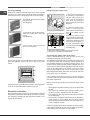
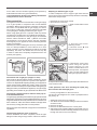
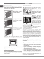
Built-in appliances
Use an appropriate cabinet to ensure that the appliance
operates properly:
• The panels adjacent to the oven must be made of heat-
resistant material.
• Cabinets with a veneer exterior must be assembled with
glues which can withstand temperatures of up to 100°C.
• To install the oven under the counter (see diagram) or
in a kitchen unit, the cabinet must have the following
dimensions:
595 mm.
595 mm.
25 mm.
545 mm.
5 mm.
567 mm.
23 mm.
575-585 mm.
45 mm.
558 mm.
547 mm. min.
! The appliance must not come into contact with electrical
parts once it has been installed.
The indications for consumption given on the data plate
have been calculated for this type of installation.
Ventilation
To ensure adequate ventilation, the back panel of the
cabinet must be removed. It is advisable to install the oven
so that it rests on two strips of wood, or on a completely
at surface with an opening of at least 45 x 560 mm (see
diagrams).
560 mm.
45 mm.

8
GB
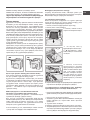
Centring and xing
Position the 4 tabs on the side of the oven, in line with the
4 holes on the outer frame. Adjust the tabs according to
the thickness of the cabinet side panel, as shown below:
20 mm thick: take off the removable
part of the tab
(see diagram);
18 mm thick: use the rst groove,
which has already been set in the
factory
(see diagram);
16 mm thick: use the second
groove (see diagram).
Secure the appliance to the cabinet by opening the oven
door and putting 4 screws into the 4 holes on the outer
frame.
! All parts which ensure the safe operation of the appliance
must not be removable without the aid of a tool.
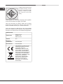
Electrical connection
Ovens equipped with a three-pole power supply cable are
designed to operate with alternating current at the voltage
and frequency indicated on the data plate located on the
appliance (see below).
Fitting the power supply cable
1. Open the terminal board
by inserting a screwdriver
into the side tabs of the
cover. Use the screwdriver
as a lever by pushing it
down to open the cover (see
diagram).
2. Install the power supply
cable by loosening the
cable clamp screw and the
three wire contact screws
L-N- .
Connect the wires to the
corresponding terminals:
the Blue wire to the terminal
marked (N), the Brown wire
to the terminal marked (L)
and the Yellow/Green wire
to the terminal marked
(see diagram).
3. Secure the cable by fastening the clamp screw.
4. Close the cover of the terminal board.
Connecting the supply cable to the mains
Install a standardised plug corresponding to the load
indicated on the data plate (see table).
The appliance must be directly connected to the mains using
an omnipolar switch with a minimum contact opening of 3
mm installed between the appliance and the mains. The
switch must be suitable for the charge indicated and must
comply with current electrical regulations (the earthing wire
must not be interrupted by the switch). The supply cable
must be positioned so that it does not come into contact
with temperatures higher than 50°C at any point (the back
panel of the oven, for example).
! The installer must ensure that the correct electrical
connection has been performed and that it is fully compliant
with safety regulations.
Before connecting the appliance to the power supply, make
sure that
• The appliance is earthed and the plug is compliant with
the law.
• The socket can withstand the maximum power of the
appliance, which is indicated on the data plate.
• The voltage is in the range between the values indicated
on the data plate.
• The socket is compatible with the plug of the appliance.
If the socket is incompatible with the plug, ask an
authorised technician to replace it. Do not use extension
cords or multiple sockets.
! Once the appliance has been installed, the power supply
cable and the electrical socket must be easily accessible.
! The cable must not be bent or compressed.
N
L

GB
9
! The cable must be checked regularly and replaced by
authorised technicians only (see Assistance).
! The manufacturer declines any liability should these
safety measures not be observed.
Gas connection
The appliance should be connected to the main gas supply
or to a gas cylinder in compliance with current National
regulations. Before carrying out the connection, make sure
the cooker is compatible with the gas supply you wish to
use. If this is not the case, follow the instructions indicated
in the paragraph “Adapting to different types of gas.”
When using liquid gas from a cylinder, install a pressure
regulator that complies with current National regulations.
! Check that the pressure of the gas supply is consistent
with the values indicated in Table 1 (“Burner and nozzle
specications”) since this will ensure the safe operation
and longevity of your appliance while maintaining efcient
energy consumption.
! Should you need to install a gas hob on top of a built-in gas
oven, it is strictly forbidden to connect the two or to use a
single cut-off tap. The two appliances should be connected
separately, and each one should have its own stop tap
in order to make them completely independent from one
another (see gures).
NO
OK
Connection with a rigid pipe (copper or steel)
! Connection to the gas system must be carried out in such a
way as not to place any strain of any kind on the appliance.
There is an adjustable L-shaped pipe tting on the appliance
supply ramp and this is tted with a seal in order to prevent
leaks. The seal must always be replaced after rotating the pipe
tting (the seal is provided with the appliance). The gas supply
pipe tting is a threaded 1/2 gas cylindrical male attachment.
Connecting a exible jointless stainless steel pipe to
a threaded attachment
The gas supply pipe tting is a threaded 1/2 gas cylindrical male
attachment. These pipes must be installed so that they are never
longer than 2000 mm when fully extended. Once connection has
been carried out, make sure that the exible metal pipe does
not touch any moving parts and is not compressed.
! Only use pipes and seals that comply with current National
regulations.
Checking the tightness of the connection
! When installation has been completed, check the pipe
ttings for leaks using a soapy solution. Never use a ame.
Adapting to different types of gas
In order to adapt the oven to a type of gas other than the
type for which it was manufactured (indicated on the label),
follow these simple steps:
• Replacing the oven burner nozzle
1. Open the oven door fully.
2. Slide out the bottom of the
oven.
V
3. Unscrew the burner
fastening screws.
4. Remove screw “V” and
then the oven burner.
5. Unscrew the oven burner
nozzle using the special
socket spanner for the
nozzles, or better still a 7 mm
socket spanner, and replace
it with a nozzle suited to the
new type of gas (see Table 1).
6. Replace all the parts, following the steps described above
in the reverse order.
! Take particular care when handling the spark plug
wires and the thermocouple pipes.
• Primary air regulation for the oven burner
The burner was designed not to need any adjustments to
the primary air.
• Setting the oven burner to minimum
1. Turn the knob rst to the Max setting for about 10 minutes
and then to Min.
2. Remove the knob.
3. Remove the disk fastened to the control panel.
4. Adjust the screw located outside the thermostat cock pin
until the ame is small but steady (the ame can be seen
through the slots on the oven bottom).

10
GB
5. Make sure the burner does
not switch off when you turn
the knob from Max to Min
quickly, or when you open
and close the oven door
quickly.
! If the appliance is connected to liquid gas, the regulation
screw must be fastened as tightly as possible.
! Once this procedure is nished, replace the old rating
sticker with one indicating the new type of gas used. This
sticker is available from any of our Service Centres.
! If the gas pressure is different from the recommended
pressure, a suitable pressure regulator must be tted to the
inlet pipe in accordance with current National Regulations.
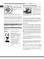
DATA PLATE
Dimensions
width 43.5 cm
height 31 cm
depth 43.5 cm
Volume
58 l
Electrical
connections
see data plate
Gas features
see data plate
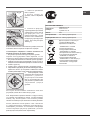
This appliance conforms to the
following European Economic
Community directives:
2006/95/EEC dated 12/12/06
(Low Voltage) and subsequent
amendments - 2004/108/EEC
dated 15/12/04 (Electromagnetic
compatibility) and subsequent
amendments - 93/68/EEC dated
22/07/93 and subsequent
amendments. 2009/142/EEC
dated 30/11/09 (Gas) and
subsequent amendments.
2012/19/EC and subsequent
amendments.

GB
11
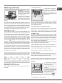
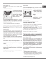
Start-up and use
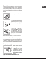
WARNING! The oven is
provided with a stop system
to extract the racks and
prevent them from coming
out of the oven (1).
As shown in the drawing,
to extract them completely,
simply lift the racks, holding
them on the front part, and
pull (2).
! The rst time you use your appliance, heat the empty oven
with its door closed at its maximum temperature for at least half
an hour. Ensure that the room is well ventilated before switching
the oven off and opening the oven door. The appliance may emit
a slightly unpleasant odour caused by protective substances
used during the manufacturing process burning away.
Starting the oven
This knob is used not only to select the different oven
modes, but also to choose the right cooking temperature
for various foods from among the temperatures shown on
the knob itself (the range is from 140°C to 240°C inclusive).
The electronic ignition device of the oven is built into the
control knob. To light the oven burner, press the OVEN
knob in as far as possible and turn it anti-clockwise, setting
it to position (keeping the oven door shut). The oven is
equipped with a safety device. After lighting the burner allow
the gas to circulate until the safety thermocouple is heated
by keeping the OVEN knob pressed in for about 6 seconds.
! The electronic ignition device of the oven burner must not
be activated for more than 15 seconds. If the burner fails to
light after 15 seconds, stop pressing the OVEN knob, open
the oven door and wait for at least one minute before you
try to light the burner again.
The cooking temperature is selected by matching the
desired temperature with the reference mark on the control
panel; the complete range of temperatures is shown below:
Min• 150• 180• 220
•M
ax
140145 160200 230240
The oven will automatically reach the temperature set, and
the thermostat, which is controlled by the knob, will keep
the temperature constant.
Switching the oven on manually
In the event of a power failure, the oven burner can be lit
manually:
1. Open the oven door.
F
2. Hold a match or lighter near
the burner hole as shown in
the gure, press knob F (see
figure) in fully and turn it
anticlockwise, setting it to the
Max position.
The oven is equipped with a safety device. After lighting
the burner allow the gas to circulate until the safety
thermocouple is heated by keeping the OVEN knob pressed
in for about 6 seconds.
3. Once the burner is lit, shut the oven door.
! If the burner ame is accidentally extinguished, turn the OVEN
control knob to the off position, open the oven door and wait
for at least one minute before trying to light the burner again.
The GRILL knob
Your oven is equipped with an electric grill. The extremely high
and direct temperature of the grill makes it possible to brown
the surface of meats and roasts while locking in the juices to
keep them tender. The grill is also highly recommended for
dishes that require a high surface temperature: beef steaks,
veal, rib steak, llets, hamburgers etc...
Some examples of how the grill may be used are included
in the “Practical Cooking Advice” section.
! When using the grill, the oven door must be kept shut.
! Never put objects directly on the bottom of the oven - this
could result in damage to the enamel coating.
! Always place cookware on the rack(s) provided.
Cooling ventilation
In order to cool down the external temperature of the oven,
some models are tted with a cooling fan that blows air out
between the control panel and the oven door.
! Once the cooking has been completed, the cooling fan
remains on until the oven has cooled down sufciently.
Turnspit*
To operate the rotisserie
function (see diagram)
proceed as follows:
1. Place the dripping pan in
position 1.
2. Place the rotisserie support
in position 3 and insert the spit
in the hole provided on the
back panel of the oven.
3. Start the rotisserie using
the knob to select ;
* Only available in certain models.

12
GB
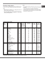
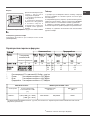
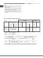
Table 1Liquid Ga
sN
atural Gas
Bur ner Ther mal Power
kW (p.c.s.* )
By-Pass
1/100
Nozzle
1/100
Flow*
g/h
Nozzl e
1/100
Flow*
l/h
Nozzle
1/100
Flow*
l/h
Nomina lReduced(mm)(mm) *** ** (mm) (mm)
Oven 2,60 1,00 49 78 189186 119248 13
22
48
Suppl y
Pressur es
Nominal (mbar )
Minimum (mbar)
Maximum (mbar)
28-3 0
20
35
37
25
45
20
17
25
13
6,5
18
Electric Part
Category Thermal Power
kW (1)
Voltage frequency Power
(W)
II2H3+
2,60 (189 g/h - G30)
(186 g/h - G31)
220-240V~ 50/60Hz2250
(1) The values in g/h refer to the capacities with liquid gas (Butane, Propane).
Gas Part
Oven light
This is switched on by pressing the LIGHT button.
How to use the timer
1. To set the buzzer, turn the TIMER knob clockwise almost
one complete revolution.
2. Turn the knob anticlockwise to set the desired time: align
the minutes shown on the knob with the indicator on the
control panel.
3. The timer operates in minutes: when the selected time
has elapsed, a buzzer will sound.
! The timer does not switch the oven on or off.
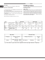
Cooking modes
Cooking modes
GRILL mode
The top heating element comes on. The extremely high and
direct temperature of the grill makes it possible to brown the
surface of meats and roasts while locking in the juices to
keep them tender. The grill is also highly recommended for
dishes that require a high surface temperature: beef steaks,
veal, rib steak, llets, hamburgers etc... Always cook in this
mode with the oven door closed.

GB
13
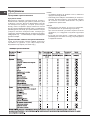
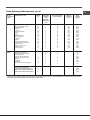
Selector
knob
setting
Food to be cooked Weight
(in kg)
Cooking
rack
position
from oven
bottom
Preheating time
(minutes)
Thermostat
knob
setting
Cooking
time
(minutes)
Oven
Lasagne
Cannelloni
Pasta bakes
Veal
Chicken
Tu rkey roll
Duck
Rabbit
Pork loin
Leg of lamb
Mackerels
Dentex
Tr out baked in foil
Neapolitan-style pizza
Dry biscuits
Ta rt
Chocolate cake
Leavened cakes
2,5
2,5
2,2
1,7
1,5
2,5
1,8
2,0
1,5
1,8
1,3
1,5
1,0
0,6
0,5
1,1
1,0
1,0
3
3
3
2
3
3
3
3
3
3
3
3
3
3
4
3
3
4
10
10
10
10
10
10
10
10
10
10
10
10
10
15
15
15
15
15
200
200
200
210
200
200
200
200
200
200
200
180
200
210
180
180
165
165
55-60
40-45
50-55
80-90
70-80
80-90
90-100
80-90
70-80
80-90
30-40
30-40
30-35
15-20
25-30
30-35
50-60
50-60
Grill
Soles and cuttlefish
Squid and prawn kebabs
Cod filet
Grilled vegetables
Veal steak
Chops
Hamburgers
Sausages
To asted sandwiches
1
1
1
1
1
1,5
1
1,7
n.° 4
4
4
4
4
4
4
4
4
4
5
3
3
-
5
5
3
5
3
-
-
-
-
-
-
-
-
-
6
4
10
8-10
20-25
20-25
10-15
20-25
2-3
With rotisserie
(where present)
Veal on the spit
Chicken on the spit
Lamb on the spit
1.0
1.5
1.0
-
-
-
-
-
-
-
-
-
80-90
80-90
80-90
! Cooking times are approximate and may vary according to personal taste. When cooking using the grill, the
dripping pan must always be placed on the 1st oven rack from the bottom.
Cooking advice table
Practical cooking advice
! In the GRILL cooking mode, place the dripping pan in
position 1 to collect cooking residues (fat and/or grease).
GRILL
• Place the grill in position 3 or 4, making sure that the
food is in the centre of the grill.
• We recommend that you set the maximum power level.
The top heating element is regulated by a thermostat
and may not always be on.
PIZZA
• Use a light aluminium pizza pan. Place it on the rack
provided.
For a crispy crust, do not use the dripping pan (prevents
crust from forming by extending cooking time).
• If the pizza has a lot of toppings, we recommend adding
the mozzarella cheese to the top of the pizza halfway
through the cooking process.

14
GB
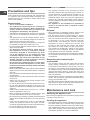
Precautions and tips
! This appliance has been designed and manufactured
in compliance with international safety standards. The
following warnings are provided for safety reasons and
must be read carefully.
General safety
• This is a class 3 built-in appliance.
• Gas appliances require regular air exchange to
maintain efcient operation. When installing the
cooker, follow the instructions provided in the
paragraph on “Positioning” the appliance.
• The appliance was designed for domestic use inside the
home and is not intended for commercial or industrial
use.
• The appliance must not be installed outdoors, even in
covered areas. It is extremely dangerous to leave the
appliance exposed to rain and storms.
• When moving or positioning the appliance, always use
the handles provided on the sides of the oven.
• Do not touch the appliance while barefoot or with wet or
damp hands and feet.
• The appliance must be used by adults only for
the preparation of food, in accordance with the
instructions provided in this booklet. Any other
use of the appliance (e.g. for heating the room)
constitutes improper use and is dangerous. The
manufacturer may not be held responsible for any
damage caused as a result of improper, incorrect
and unreasonable use of the appliance.
• Do not touch the heating elements or certain parts
of the oven door when the appliance is in use; these
parts become extremely hot. Keep children well away
from the appliance.
• Make sure that the power supply cables of other electrical
appliances do not come into contact with the hot parts of
the oven.
• The ventilation and heat dispersal openings must never
be obstructed.
• Always grip the oven door handle in the centre: the ends
may be hot.
• Always use oven gloves when placing cookware in the
oven or when removing it.
• Do not use aluminium foil to line the bottom of the oven.
• Do not place ammable materials in the oven: if the
appliance is switched on accidentally, the materials could
catch re.
• Always make sure the knobs are in the “●”/“○” position
when the appliance is not in use.
• When unplugging the appliance, always pull the plug
from the mains socket; do not pull on the cable.
• Do not perform any cleaning or maintenance work without
having disconnected the appliance from the electricity
mains.
• If the event of malfunctions, under no circumstances
should you attempt to perform the repairs yourself.
Contact an authorised Service Centre (see Assistance).
• Do not rest objects on the open oven door.
• Do not let children play with the appliance.
• The appliance should not be operated by people
(including children) with reduced physical, sensory or
mental capacities, by inexperienced individuals or by
anyone who is not familiar with the product. These
individuals should, at the very least, be supervised by
someone who assumes responsibility for their safety or
receive preliminary instructions relating to the operation
of the appliance.
• The appliance is not intended to be operated by
means of an external timer or separate remote-
control system.
Disposal
• When disposing of packaging material: observe local
legislation so that the packaging may be reused.
• The European Directive 2012/19/EC on Waste
Electrical and Electronic Equipment (WEEE), requires
that old household electrical appliances must not
be disposed of in the normal unsorted municipal
waste stream. Old appliances must be collected
separately in order to optimise the recovery and
recycling of the materials they contain and reduce
the impact on human health and the environment.
The crossed out “wheeled bin” symbol on the product
reminds you of your obligation, that when you dispose
of the appliance it must be separately collected.
Consumers should contact their local authority or retailer
for information concerning the correct disposal of their
old appliance.
Respecting and conserving the
environment
• You can help to reduce the peak load of the electricity
supply network companies by using the oven in the
hours between late afternoon and the early hours of
the morning. The cooking mode programming options,
the “delayed cooking” mode (see Cooking modes) and
“delayed automatic cleaning” mode (see Care and
Maintenance) in particular, enable the user to organise
their time efciently.
• Always keep the oven door closed when using the GRILL
modes: This will achieve improved results while saving
energy (approximately 10%).
• Regularly check the door seals and wipe clean to ensure
they are free of debris so that they stick properly to the
door and do not allow heat to disperse.
Maintenance and care
Switching the appliance off
Disconnect your appliance from the electricity supply before
carrying out any work on it.
Cleaning the appliance
• The stainless steel or enamel-coated external parts and
the rubber seals may be cleaned using a sponge that
has been soaked in lukewarm water and neutral soap.
Use specialised products for the removal of stubborn
stains. After cleaning, rinse and dry thoroughly. Do not
use abrasive powders or corrosive substances.

GB
15
• The inside of the oven should ideally be cleaned after
each use, while it is still lukewarm. Use hot water and
detergent, then rinse well and dry with a soft cloth. Do
not use abrasive products.
• All accessories - with the exception of the sliding racks
- can be washed like everyday crockery, and are even
dishwasher safe.
! Never use steam cleaners or pressure cleaners on the
appliance.
Cleaning the oven door
Clean the glass part of the oven door using a sponge and a non-
abrasive cleaning product, then dry thoroughly with a soft cloth.
Do not use rough abrasive material or sharp metal scrapers as
these could scratch the surface and cause the glass to crack.
To clean the oven more thoroughly, you can remove its door:
1. Open the oven door fully (see
diagram).
F
2. Use a screwdriver to lift up and
turn the small levers F located on
the two hinges (see diagram);
F
3. Grip the door on the two external
sides and close it approximately
half way. Unlock the door by
pressing on the clamps F, then pull
the door towards you lifting it out of
its seat (see diagram);
To replace the door, reverse this sequence.
Inspecting the seals
Check the door seals around the oven regularly. If the seals
are damaged, please contact your nearest Service Centre
(see Assistance). We recommend that the oven is not used
until the seals have been replaced.
Replacing the light bulb
To replace the oven light
bulb:
1. Remove the glass cover
of the lamp-holder.
2. Remove the light bulb and
replace it with a similar one:
Wattage 25 W, cap E 14.
3. Replace the glass cover
(see diagram).
! Do not use the oven lamp as/for ambient lighting.

16
RS
Установка
! Важно сохранить данное руководство для его
последующих консультации. В случае продажи,
передачи изделия или при переезде на новое место
жительства необходимо проверить, чтобы руководство
оставалось вместе с изделием, для того чтобы его новыи
владелец мог ознакомиться с правилами эксплуатации
и с соответствующими предупреждениями.
! Внимательно прочитаите инструкции: в них содержатся
важные сведения об установке, эксплуатации и
безопасности изделия.
Расположение
! Не разрешаите детям играть с упаковочными
материалами. Упаковочные материалы должны быть
уничтожены в соответствии с правилами раздельного
сбора мусора (см. Предосторожности и рекомендации).
! Монтаж изделия производится в соответствии
с данными инструкциями квалифицированными
специалистами. Неправильныи монтаж изделия может
стать причинои повреждения имущества и причинить
ущерб людям и домашним животным.
! Данное изделие может быть установлено и
использоваться только в помещениях с постояннои
вентиляциеи в соответствии с положениями
деиствующих Нормативов. Необходимо соблюдать
следующие требования:
• в помещении должна быть предусмотрена система
дымоудаления в атмосферу, выполненная в
виде вытяжного зонта или электровентилятора,
автоматически включающихся каждыи раз, когда
включается изделие.
• В помещении должна быть предусмотрена система,
обеспечивающая достаточныи приток воздуха для
надлежащего горения. Расход воздуха, необходимого
для горения, должен быть не менее 2 м
3
/час на кВт
установленнои мощности.
Приток воздуха может
обеспечиваться непосредственно
снаружи здания через
воздуховод полезным сечением
не менее 100 см
2
и диаметром,
исключающим возможность
случаиного засорения.
A
Или же воздухозабор может
осуществляться из смежных
помещении, оснащенных
вентиляционным отверстием,
сообщающимся с улицеи, как
описано выше, при условии,
что это не общие зоны здания,
пожароопасные помещения и
не спальни.
• Сжиженныи газ пропан-бутан тяжелее воздуха и
следовательно застаивается внизу. По этои причине
помещения, в которых установлены баллоны с СНГ
(сжиженным натуральным газом) должны иметь
вентиляционные отверстия внизу, сообщающиеся с
улицеи, для удаления возможных утечек газа. Поэтому
баллоны с СПГ должны быть опорожнены или оставаться
частично заполненными; они не должны размещаться
или храниться в подземных помещениях и хранилищах
(подвалах, и т.д.). Следует держать в помещении только
один рабочии баллон, расположенныи таким образом,
чтобы он не подвергался прямому воздеиствию
источников тепла (печеи, каминов и т.д.), которые могут
привести к нагреву баллона свыше 50°C.
Встроенный монтаж
Для обеспечения исправного функционирования
встраиваемого изделия кухонный элемент должен иметь
соответствующие характеристики:
• панели кухонных элементов, прилегающих к духовому
шкафу, должны быть выполнены из термостойкого
материала;
• клей кухонных элементов элементов, шпонированных
деревом, должен быть устойчивым к температуре 100°C.
• для встраивания духового шкафа под кухонным
топом (см. схему) или в пенал ниша кухонного
элемента должна иметь следующие размеры:
595 mm.
595 mm.
25 mm.
545 mm.
5 mm.
567 mm.
23 mm.
575-585 mm.
45 mm.
558 mm.
547 mm. min.
! После встраивания изделия в кухонный элемент
должна быть исключена возможность касания к
электрическими частями.
Расход электроэнергии, указанный на паспортной
табличке изделия, был замерян для данного типа монтажа.
Вентиляция
Для обеспечения надлежащеи вентиляции необходимо
снять заднюю панель ниши кухонного элемента.

17
RS
Рекомендуется установить духовои шкаф на два
деревянных бруска или на сплошное основание с
отверстием диаметром не менее 45 х 560 мм (см чертежи).
560 mm.
45 mm.
Центровка и крепление
4 крепежных элемента с боков духового шкафа должны
быть отрегулированы в соответствии с 4 отверстиями
в периметральной раме в зависимости от толщины
боковой панели кухонного элемента:
толщина 20 мм: полностью
удалите съемную часть
крепежного элемента (см.
схему);
толщина 18 мм: используйте
первый паз, согласно уже
готовой конфигурации
производителя (см. схему);
толщина 16 мм: используйте
второй паз (см. схему).
! Все защитные элементы должны быть закреплены
таким образом, чтобы их можно было снять только при
помощи специального инструмента.
Электрическое подключение
Духовые шкафы, укомплектованные трехполюсным
сетевым кабелем, расчитаны на функционирование
с переменным током с напряжением и частотой
электропитания, указанными на паспортной табличке
с данными (см. ниже).
Подсоединение сетевого кабеля
1. Откройте зажимную
коробку, нажав при помощи
отвертки на выступы с
боков крышки: потяните
и откройте крышку (см.
схему).
2. Порядок подсоединения
сетевого кабеля: отвинтите
винт кабельного сальника
и три винта контактов L-N-
и затем прикрепите
провода под головками
винтов, соблюдая цветовую
маркировку Синий (N)
Коричневый (L) Желто-
зеленый (см. схему).
3. Закрепите сетевой
кабель в специальном
кабельном сальнике.
4. Закройте крышку
зажимной коробки.
Подсоединение сетевого шнура изделия к сети
электропитания
Установите на сетевой кабель нормализованную
штепсельную вилку, расчитанную на нагрузку, указанную
на паспортной табличке (см. сбоку).
В случае прямого подключения к сети электропитания
между изделием и сетью необходимо установить
многополюсный выключатель с минимальным
расстоянием между контактами 3 мм, расчитанный
на данную нагрузку и соответствующий действующим
нормативам (выключатель не должен размыкать провод
заземления). Сетевой кабель должен быть расположен
таким образом, чтобы ни в одной точке его температура
не превышала температуру помещения более чем на
50°C (например, задняя панель духового шкафа).
N
L

18
RS
! Электромонтер несет ответственность за правильное
подключение изделия к электрическои сети и за
соблюдение правил безопасности.
Перед подключением изделия к сети электропитания
проверьте следующее:
• розетка должна быть соединена с заземлением и
соответствовать нормативам;
• сетевая розетка должна быть рассчитана на
максимальную потребляемую мощность изделия,
указанную в таблице технических характеристик;
• напряжение и частота тока сети должны
соответствовать электрическим данным изделия;
• сетевая розетка должна быть совместима со
штепсельнои вилкои изделия. В противном случае
замените розетку или вилку; не используите
удлинители или троиники.
! Изделие должно быть установлено таким образом,
чтобы кабель электропитания и сетевая розетка были
легко доступны.
! Кабель электропитания изделия не должен быть согнут
или сжат.
! Регулярно проверяйте состояние кабеля
электропитания и в случае необходимости поручите
его замену только уполномоченным техникам (см.
Техническое обслуживание).
! Фирма снимает с себя всякую ответственность
в случае несоблюдения вышеописанных правил.
Подсоединение к газопроводу
Подсоединение изделия к газопроводу или к газовому
баллону должно осуществляться в соответствии с
действующими национальныи нормативами и с их
последующими поправками и только после проверки
соответствия изделия типу газа, к которому он
подсоединяется. В случае несоответствия выполнить
операции, описанные в параграфе “Настройка на
различные типы газа”.
В случае использования сжиженного газа из баллона
использовать регуляторы давления, соответствующие
действующимнациональным нормативам и их
последующим поправкам.
! Для надежного функционирования, рационального
использования энергии и более длительного срока
службы электрического изделия проверьте, чтобы
давление подачи газа соответствовало значениям,
указанным в таблице 1 “Характеристики газовых горелок
и форсунок”.
! В случае установки газовой плиты вместе с газовой
встроенной духовкой категорически запрещается
соединять эти два устройства или использовать
единый газовый отсечной кран. Эти устройства должны
быть независимыми друг от друга, подсоединяться по
отдельности, и каждое из них должно иметь отдельный
отсечной газовый кран (см. схемы).
NO
OK
Подсоединение при помощи жесткой трубы
(медной или стальной)
! Подсоединение к газопроводу не должно оказывать
каких-либо нагрузок на изделие.
На патрубке подачи газа в изделия имеется
вращающееся колено L с уплотнительной прокладкой.
При необходимости повернуть колено обязательно
замените уплотнительную прокладку (прилагающется
к изделию). Патрубок подачи газа в изделие имеет
цилиндрическую наружную резьбу 1/2 газ.
Подсоединение при помощи гибкого шланга из
нержавеющей стали со сплошными стенками с
резьбовыми соединениями.
Патрубок подачи газа в изделие имеет цилиндрическую
наружную резьбу 1/2 газ.
Подсоединение таких шлангов должно производиться
таким образом, чтобы их длина при максимальном
растяжении не превышала 2000 мм. По завершении
подсоединения проверьте, чтобы металлический гибкий
шланг не касался подвижных частей или не был сжат.
! Используйте только шланги и металлические
алюминиевые или резиновые уплотнительные
прокладки, соответствующие действующим
национальным нормативам.
Проверка уплотнения
! По завершении подсоединения проверьте прочность
уплотнения всех патрубков при помощи мыльного
раствора, но никогда не пламенем.
Настройка на различные типы газа
Для настройки духового шкафа на тип газа, отличающийся
от газа, на который она расчитана (указан на этикетке),
необходимо выполнить следующие операции:
• Порядок замены форсунки газовой горелки духового
шкафа:
1. полностью откройте дверцу духовки
2. выньте съемное днище
духовки

19
RS
V
3. отвинтите крепежные
винты горелки
4. выньте горелку из
духовки, сняв “V”-образный
винт;
5. отвинтите форсунку
горелки духовки при помощи
специального полого ключа
для форсунок, или, что
предпочтительнее, полым
ключом 7 мм и замените ее
на форсунку, пригодную для
нового типа газа (смотрете
таблицу 1).
6. Восстановите на место все комплектующие, выполняя
описанные выше операции в обратном порядке.
! Необходимо обращать особое внимание на
провода свечей и на трубки термопар.
• Регуляция первичного воздуха горелки духовки
Горелка сконструирована таким образом, что не
нуждается в какой-либо регуляции первичного воздуха.
• Регуляция минимального пламени горелки духовки
1. поверните регулятор в положение Min, после того как он
находился в положении Max примерно в течении 10 минут
2. снимите рукоятку
3. снимите диск, прикрепленный к передней панели
4. поверните винт регуляции, расположенный снаружи стержня
термостата, вплоть до получения стабильного малого
пламени (пламя видно через отверстия в днище духовки);
5. затем проверить, чтобы
горелка не гасла при резком
вращении рукоятки-
регулятора из положения
Max в положение Min или
при резком открывании или
закрывании дверцы
духовки.
! В случае использования сжиженного газа винт
регуляции должен быть завинчен до упора.
! По завершении операции замените старую этикетку
со старыми настройками на новую, соответствующую
новому типу используемого газа. Этикетку можно
заказать в наших Центрах Технического Обслуживания.
! Если давление используемого газа отличается
от предусмотренного давления (или варьирует),
необходимо установить на питающем газопроводе
соответствующий регулятор давления (согласно
действующим национальным нормативам).
ПАСПОРТНАЯ ТАБЛИЧКА
Электропитание
См. таблицу характеристик
Характеристики газа
См. таблицу характеристик
Габаритные
размеры
ширина 43,5 см.
высота 31 см.
глубина 43,5 см.
Объем
58 л
Данное изделие соответствует
следующим Директивам
Европейского сообщества:
- 2006/95/CEE от 12/12/06
(Низкое напряжение) и
последующим изменениям.
- 2004/108/CEE от 15/12/04
(Электромагнитная совместимость)
и последующим изменениям.
- 93/68/CEE от 22/07/93 и
последующим изменениям.
- 2009/142/CEE от 30/11/09 (Газ) с
последующими изменениями.
- 2012/19/CE и последующим
изменениям.

20
RS
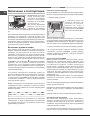
Включение и эксплуатация
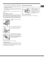
ВНИМАНИЕ! Духовой
шкаф укомплектован
системой блокировки
решеток, позволяющей
вынимать их из духовки
не полностью (1).
Для полного вынимания
решеток достаточно
поднять их, как показано
на схеме, взяв их за передний край, и потянуть на себя
(2).
! При первом включении духового шкафа рекомендуем
прокалить его примерно в течение 30 минут при
максимальной температуре с закрытой дверцей. Затем
выключите духовой шкаф, откройте дверцу и проветрите
помещение. Запах, который вы можете почувствовать,
вызван испарением веществ, использованных для
предохранения духового шкафа.
Включение духового шкафа
При помощи рукоятки духового шкафа вы можете
выбрать различные режимы и установить температуру,
указанную на самой рукоятке (от 140°C до 240°C),
наиболее подходящую для приготовления блюд.
Электронное устройство зажигания встроено внутри
рукоятки. Для зажигания горелки духовки нажмите до
упора и поверните против часовой стрелки рукоятку
ДУХОВКИ в положение Max (при закрытой дверце
духовки). Так как духовка оснащена защитным
устройством, после зажигания горелки необходимо
держать рукоятку ДУХОВКИ нажатой примерно в
течение 6 секунд для притока газа вплоть до нагревания
защитной термопары.
! Устройство электронного зажигания горелки не
должно оставаться нажатым в течение более 15 секунд.
Если по истечении 15 секунд горелка не зажглась,
отпустите рукоятку ДУХОВКИ, откройте дверцу духовки
и подождите примерно 1 минуту перед повторной
попыткой зажечь горелку.
Выбор температуры приготовления осуществляется
совмещением нужного значения с отметкой на панели
управления. Ниже приводится полный температурный
диапазон духовки.
Min• 150• 180• 220
•M
ax
140145 160200 230240
Духовка автоматически нагревается до заданной
температуры, которая поддерживается неизменной
при помощи контрольного устройства (термостата),
управляемого рукояткой.
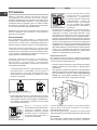
Зажигание духовки вручную
В случае временного отключения электроэнергии можно
включить горелку духовки вручную следующим образом:
1. откройте дверцу духовки
F
2. поднесите спичку или
кухонную зажигалку, как
показано на рисунке,
нажмите до упора и
поверните против часовой
стрелки рукоятку ДУХОВКИ
вплоть до положения Max.
Так как духовка оснащена защитным устройством,
после зажигания горелки необходимо держать рукоятку
ДУХОВКИ нажатой примерно в течение 6 секунд для
притока газа вплоть до нагревания защитной термопары.
3. После зажигания горелки закройте дверцу духовки.
! В случае внезапного гашения пламени горелки
перекройте рукоятку ДУХОВКИ, откройте дверцу
духовки и подождите примерно 1 минуту до повторной
попытки зажечь горелку.
Рукоятка-регулятор ГРИЛЯ
Ваша духовка оснащена электрическим грилем.
Значительная температура прямого действия гриля
позволяет получить быстрое образование корочки
на поверхности продукта, которая препятствует
выходу соков и сохраняет продукт нежным и сочным
внутри. Использование функции гриль в особенности
рекомендуется для блюд, для приготовления которых
требуется высокая поверхностная температура:
телячьих и говяжьих бифштексов, антрекотов, вырезки,
гамбургеров и т.д.
В параграфе “Практические советы по приготовлению”
приводятся некоторые примеры использования
духового шкафа.
! При использовании режима гриль необходимо держать
дверцу духовки закрытой.
! Никогда не ставьте никаких предметов на дно духового
шкафа, так как они могут повредить эмалированное
покрытие.
! Всегда ставьте посуду на прилагающуюся решетку.
Охладительная вентиляция
Для понижения температуры вокруг работающего
духового шкафа некоторые модели оснащаются
охладительным вентилятором. Этот вентилятор
направляет струю воздуха между панелью управления
и дверцей духового шкафа.
! По завершении приготовления вентилятор продолжает
работать вплоть до надлежащего охлаждения духовки.
Страница загружается ...
Страница загружается ...
Страница загружается ...
Страница загружается ...
Страница загружается ...
Страница загружается ...
Страница загружается ...
Страница загружается ...
Страница загружается ...
Страница загружается ...
Страница загружается ...
Страница загружается ...
Страница загружается ...
Страница загружается ...
Страница загружается ...
Страница загружается ...
-
 1
1
-
 2
2
-
 3
3
-
 4
4
-
 5
5
-
 6
6
-
 7
7
-
 8
8
-
 9
9
-
 10
10
-
 11
11
-
 12
12
-
 13
13
-
 14
14
-
 15
15
-
 16
16
-
 17
17
-
 18
18
-
 19
19
-
 20
20
-
 21
21
-
 22
22
-
 23
23
-
 24
24
-
 25
25
-
 26
26
-
 27
27
-
 28
28
-
 29
29
-
 30
30
-
 31
31
-
 32
32
-
 33
33
-
 34
34
-
 35
35
-
 36
36


HOTPOINT/ARISTON 7OFH G (WH) RU/HA Руководство пользователя
- Категория
- Печи
- Тип
- Руководство пользователя
- Это руководство также подходит для
Задайте вопрос, и я найду ответ в документе
Поиск информации в документе стал проще с помощью ИИ
Похожие модели бренда
-
HOTPOINT/ARISTON 7OFK G X RU/HA S Руководство пользователя
-
Hotpoint 7OFHR G (OW)RU/HA Руководство пользователя
-
-
-
Indesit GOS 7 A RFH Руководство пользователя
-
Модели других брендов
-
Whirlpool C34S M57(W) RU/HA Руководство пользователя
-
-
-
Indesit FGIM K IX Руководство пользователя
-
Hotpoint-Ariston 7OFHR G(AN)RU/HA Руководство пользователя
-
-