Hotpoint Ariston 7HKEC 645 D X RU/HA Руководство пользователя
- Категория
- Кухонные плиты (варочные панели)
- Тип
- Руководство пользователя

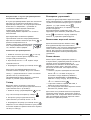
Operating Instructions
Contents
Installation, 2-4
Positioning
Electrical connection
Description of the appliance, 5-6
Control panel
Extendable cooking zones
Start-up and use, 7-10
Switching on the hob
Switching on the cooking zones
Switching off the cooking zones
Power function
Heating elements
Programming the cooking duration
Timer
Control panel lock
Switching off the hob
“Demo” mode
Practical advice on using the appliance
Safety devices
Practical cooking advice
Precautions and tips, 11
General safety
Disposal
Care and maintenance, 12
Switching the appliance off
Cleaning the appliance
Disassembling the hob
Technical description of the models, 13
HOB
GB
English,1
GB
RS
Русский, 14
7HKRC 640 B RU/HA
7HKRC 640 X RU/HA
7HKRC 641 D X RU/HA
7HKEC 645 D X RU/HA
7HKRC 631 T RU/HA
7HKRC 641 D B RU/HA
CRC 640 X RU/HA
CRC 641 DB RU/HA
CRC 631 TX RU/HA

2
GB
Installation
! Before operating your new appliance please read
this instruction booklet carefully. It contains
important information concerning the safe operation,
installation and maintenance of the appliance.
! Please keep these operating instructions for future
reference. Pass them on to any new owners of the
appliance.
Positioning
! Keep all packaging material out of the reach of
children. It may present a choking or suffocation
hazard (
see Precautions and tips
).
! The appliance must be installed by a qualified
professional in accordance with the instructions
provided. Incorrect installation may cause harm to
people and animals or may damage property.
Built-in appliance
Use a suitable cabinet to ensure that the appliance
functions properly.
• The supporting surface must be heat-resistant up
to a temperature of approximately 100°C.
• If the appliance is to be installed above an oven,
the oven must be equipped with a forced
ventilation cooling system.
• Avoid installing the hob above a dishwasher: if
this cannot be avoided, place a waterproof
separation device between the two appliances.
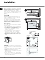
• Depending on the hob you want to install, the
cabinet must have the following dimensions (
see
figure
):
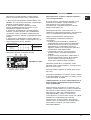
Ventilation
To allow adequate ventilation and to avoid overheating
of the surrounding surfaces the hob should be positioned
as follows:
• At a minimum distance of 40 mm from the back
panel.
• So that a minimum distance of 20 mm is
maintained between the installation cavity and the
cabinet underneath.
• Kitchen cabinets adjacent to the appliance and
taller than the top of the hob must be at least 600
mm from the edge of the hob.
FRONT SIDE
OF HOB
SUPPORTING
SURFACE
30
40
UNDERSIDE
OF HOB
5 mm
min. 20 mm
min. 20 mm
min. 40 mm
COMPARTMENT
5 mm
min. 40 mm
FAN-ASSISTED
OVEN
560 +/- 1
490 +/- 1
48
590
520

3
GB
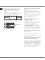
Fixing
The appliance must be installed on a perfectly level
supporting surface.
Any deformities caused by improper fixing could
affect the features and operation of the hob.
The thickness of the supporting surface
should be
taken into account when choosing
the length of the
screws for the fixing hooks:
• 30 mm thick: 17.5 mm screws
• 40 mm thick: 7.5 mm screws
Fix the hob as follows:
1. Use short flat-bottomed screws to fix the 4
alignment springs in the holes provided at the
central point of each side of the hob.
2. Place the hob in the cavity, make sure it is in a
central position and push down on the whole
perimeter until the hob is stuck to the supporting
surface.
3. For hobs with raised sides: After inserting the hob
into its cavity, insert the 4 fixing hooks (each has its
own pin) into the lower edges of the hob, using the
long pointed screws to fix them in place, until the
glass is stuck to the supporting surface.
! The screws for the alignment springs must remain
accessible.
! In order to adhere to safety standards, the
appliance must not come into contact with electrical
parts once it has been installed.
! All parts which ensure the safe operation of the
appliance must not be removable without the aid of
a tool.
Electrical connection
! The electrical connection for the hob and for any
built-in oven must be carried out separately, both for
safety purposes and to make extracting the oven
easier.
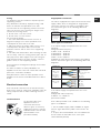
Terminal board
On the lower part of the
appliance there is a
connection box for the
different types of electricity
supply (the picture is only an
indication and is not an exact
representation of the
purchased model).
Single-phase connection
The hob is equipped with a pre-connected electricity
supply cable, which is designed for single-phase
connection. Connect the wires in accordance with
the instructions given in the following table and
diagrams:
Voltage and
mains frequency
Electrical cable Wire connection
230-240V 1+N ~
220-240V 1+N ~
50/60 Hz
: yellow/green
N
: the two blue wires together
L
: brown and black together
Other types of connection
If the mains supply corresponds with one of the
following:
Voltage and mains frequency
• 400V - 2+N ~ 50/60 Hz
• 220-240V 3 ~ 50/60 Hz
• 230-240V 3 ~ 50/60 Hz
• 400V - 2+2N ~ 50/60 Hz
Separate the wires and connect them in accordance
with the instructions given in the following table and
diagrams:
Voltage and
mains frequency
Electrical cable Wire connection
400V - 2+N ~
50/60 Hz
230-240V 3 ~
220-240V 3 ~
50/60 Hz
: yellow/green;
N: the two blue wires
together
L1: black
L2: brown
400V - 2+2N ~
50/60 Hz
: yellow/green;
N1: blue
N2: blue
L1: black
L2: brown
If the mains supply corresponds with one of the
following:
Voltage and mains frequency
• 400V 3 - N ~ 50/60 Hz
proceed as follows:
! The cable provided is not suitable for the following
types of installation.
1. Use a suitable supply cable, H05RR-F or higher,
with the right dimensions (cable cross section: 25
mm).
2. To open the terminal board, use a screwdriver as
a lever under the side tabs of the cover (
see
Terminal board picture
).
UNDERSIDE OF HOB

4
GB
3. Loosen the cable clamp screw and the terminal
board screws in accordance with the type of
connection required and position the connection
supports as shown in the following table and
diagrams.
4. Position the wires in accordance with the
information given in the following table and diagrams
and connect the appliance by tightening all the
screws for the springs as much as possible.
Voltage and
mains frequency
Electrical connections Terminal board
400V 3-N ~
50/60 Hz
Three-phase 400
5. Secure the power supply cable by fastening the
cable clamp screw, then put the cover back on.
Three-phase 400
Connecting the electricity supply cable to the
mains
If the appliance is being connected directly to the
electricity mains an omnipolar switch must be
installed with a minimum opening of 3 mm between
contacts.
! The installer must ensure that the correct electrical
connection has been made and that it is fully
compliant with safety regulations.
Before connecting the appliance to the power
supply, make sure that:
• The appliance is earthed and the plug is
compliant with the law.
• The socket can withstand the maximum power of
the appliance, which is indicated on the data
plate located on the appliance itself.
• The voltage falls within the range of values
indicated on the data plate.
• The socket is compatible with the plug of the
appliance. If the socket is incompatible with the
plug, ask an authorised technician to replace it.
Do not use extension cords or multiple sockets.
! Once the appliance has been installed, the power
supply cable and the electrical socket must be
easily accessible.
! The cable must not be bent or compressed.
! The cable must be checked regularly and replaced
by authorised technicians only.
! The manufacturer declines any liability should
these safety measures not be observed.
! Do not remove or replace the power supply cable
for any reason. Its removal or replacement will void
the warranty and the CE marking. INDESIT does not
assume liability for accidents or damage arising
from replacement/removal of the original power
supply cable. Replacement can only be accepted
when carried out by personnel authorised by
INDESIT and using an original spare part.
U-bolt
connection support
Neutral
Earth
Phase Phase Phase
1
2
3
5
4

5
GB
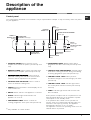
Description of the
appliance
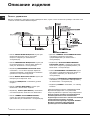
Control panel
• INCREASE POWER button switches on the
hotplate and controls the power (
see Start-up and
use
).
• REDUCE POWER button controls the power and
switches off the hotplate (
see Start-up and use
).
•
COOKING ZONE SELECTOR COOKING ZONE SELECTOR
COOKING ZONE SELECTOR COOKING ZONE SELECTOR
COOKING ZONE SELECTOR button shows a
particular cooking zone has been selected and
therefore various adjustments are possible.
• COOKING ZONE SELECTOR button is used to
select the desired cooking zone.
• POWER indicator provides a visual display for the
current heat level.
• ON/OFF button switches the appliance on and off.
• ON/OFF indicator light shows whether the
appliance is on or off.
• PROGRAMME TIMER* button controls the
cooking programme times (
see Start-up and use
).
• PROGRAMME TIMER* display shows which
programme has been selected (
see Start-up and
use
).
• COOKING ZONE PROGRAMMED* indicator lights
show which cooking zones are being used during
a cooking programme (
see Start-up and use
).
• CONTROL PANEL LOCK button prevents
accidental changes to the hob settings (
see
Start-
up and use
).
• CONTROL PANEL LOCK indicator light shows
the control panel has been locked (
see Start-up
and use
).
• TIMER* indicator light shows that the timer has
been activated
! This product complies with the requirements of the
latest European Directive on the limitation of power
consumption of the standby mode.
If no operations are carried out for a period of 2
minutes, after the residual heat indicator lights turn
off and the fan stops (if present), the appliance
automatically switches to the “off mode”.
The appliance resumes the operating mode once the
ON/OFF button is pressed.
The control panel described in this manual is only a representative example: it may not exactly match the panel
on your appliance.
ON/OFF
indicator light
CONTROLS LOCKED
indicator light
CONTROL PANEL
LOCK button
INCREASE
POWER button
COOKING ZONE PROGRAMMED*
indicator light
PROGRAMME TIMER*
display
PROGRAMME
TIMER* button
COOKING ZONE
SELECTOR buttons
REDUCE POWER
button
COOKING ZONE
SELECTED indicator light
POWER and
RESIDUAL HEAT
indicators
ON/OFF
button
TIMER*
indicator light
*
Only available in certain models.

6
GB
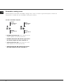
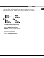
Extendable cooking zones
Certain models are fitted with extendable cooking zones. A list of controls is given below (these controls are
only present in models with the extendable cooking zone option).
Circular extendable hotplate
• DOUBLE HOTPLATE ON button switches on the
double hotplate (
see Start-up and use
).
• DOUBLE HOTPLATE ON indicator light shows
the double hotplate has been switched on.
• TRIPLE HOTPLATE ON button switches on the
triple hotplate (
see Start-up and use
).
• TRIPLE HOTPLATE ON indicator light shows
the triple hotplate has been switched on.
DOUBLE
HOTPLATE ON
indicator light
DOUBLE
HOTPLATE ON
button
TRIPLE
HOTPLATE ON
indicator light
TRIPLE
HOTPLATE ON
button

7
GB
Start-up and use
! The glue applied on the gaskets leaves traces of
grease on the glass. Before using the appliance, we
recommend you remove these with a special non-
abrasive cleaning product. During the first few hours
of use there may be a smell of rubber which will
disappear very quickly.
! A few seconds after the hob is connected to the
electricity supply, a buzzer will sound. The hob may
now be switched on.
! If the
--
--
- or
++
++
+ button is pressed for an extended
period of time, the display scrolls quickly though the
power levels and timer minutes.
Switching on the hob
To switch the hob on, press and hold the button
for approximately one second.
Switching on the cooking zones
Each cooking zone is controlled using a selector
button
and a power adjustment device
consisting of a double
--
--
- and
++
++
+ button.
• To begin operating a cooking zone, press the
corresponding control button and set the desired
power level (between 0 and 9) using the buttons
--
--
- and
++
++
+.
Power function
The power function for the cooking zones may be
used to shorten heating-up times. Activate and set
the power level for the desired cooking zone
as
described in the previous paragraph. Press and hold
the selector button corresponding to the desired
cooking zone
for at least 2 seconds. The
display, the power level indicator, will alternately
show the letter “
PP
PP
P” and the power level set
previously until the desired power level has been
reached. Once this level has been reached, the
display will revert to showing the set power level. To
deactivate this function, press and hold – for at least
2 seconds - the selector button corresponding to the
cooking zone on which the
function has been
activated; alternatively, select a different power level
using the buttons
--
--
- and
++
++
+.
Switching off the cooking zones
To switch off a cooking zone, select it using the
corresponding selector button
and:
• Press the
--
--
- button: the power of the cooking zone
will progressively decrease until it is switched off.
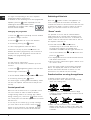
Heating elements
Two types of heating element may be installed,
depending on the appliance model: halogen and
radiant elements.
Halogen elements emit heat via radiation from the
halogen lamps they contain.
They have similar properties to gas burners: they are
easy to control and reach set temperatures quickly,
allowing you to see the power level instantly.
Radiant elements consist of a series of coils which
allow heat to be distributed evenly at the base of the
cookware, so that all slow-flame cooking may be
performed successfully, for example stews, sauces
or reheated dishes.
Programming the cooking duration
! All the cooking zones may be programmed
simultaneously, for a duration between 1 and 99
minutes.
1. Select the cooking zone using the corresponding
selector button.
2. Adjust the power level of the cooking zone.
3. Press the
programming button. The indicator
light corresponding to the selected zone will start
flashing.
4. Set the cooking duration using the
--
--
- and
++
++
+
buttons.
5. Confirm by pressing the
button or automatic
selection occurs after 10 seconds.
The timer begins counting down immediately. A
buzzer sounds for approximately 1 minute and the
cooking zone switches off when the set programme
has finished. Repeat the above procedure for each
hotplate you wish to programme.
Using multiple programmes and the display
If one or more hotplates are programmed, the
display will show the data for the hotplate with the
least time remaining, and the light corresponding to
the position of the hotplate will flash.

8
GB
The lights corresponding to the other hotplates
programmed will be switched on.
To visualise the time remaining for the other programmed
hotplates, press the
button repeatedly: the time
remaining for each hotplate will be shown
sequentially in a clockwise order, starting
from the front left hotplate.
Changing the programme
1. Press the
button repeatedly until the duration
you wish to change is shown.
2. Use the
buttons to set the new duration.
3. Confirm by pressing the
button.
To cancel a programme, follow the above
instructions. At step 2, press the
--
--
- button: the
duration decreases progressively until it reaches 0
and switches off. The programme resets and the
display exits programming mode.
Timer
The hob must be switched on.
The timer can be used to set a duration up to 99
minutes.
1. Press the
programming button until the timer
indicator light is illuminated
.
2. Set the desired duration using the
--
--
- and
++
++
+ buttons.
3. Confirm by pressing the
button.
The timer begins counting down immediately. When
the time has elapsed, a buzzer will sound (for one
minute).
Control panel lock
When the hob is switched on, it is possible to lock
the oven controls in order to avoid accidental
changes being made to the settings (by children,
during cleaning, etc.). Press the
button to lock
the control panel: the indicator light above the button
will switch on.
To use any of the controls (e.g. to stop cooking),
you must switch off this function. Press the
button for a few moments, the indicator light will
switch off and the lock function will be removed.
Switching off the hob
Press the button to switch the appliance off.
If the control panel lock has been activated, the
controls will continue to be locked even after the hob
is switched on again. In order to switch the hob on
again, you must first remove the lock function.
“Demo” mode
It is possible to set the hob to a demonstration
mode where all the controls work normally but the
heating elements do not switch on. To activate the
“demo” mode the hob must be switched on, with all
the hotplates switched off.
• Press and hold the
++
++
+ and
--
--
- buttons
simultaneously for 6 seconds. When the 6
seconds have elapsed, the ON/OFF and
CONTROLS LOCKED indicator lights will flash for
one second. Release the
++
++
+ and
--
--
- buttons and
press the
button;
• The display will show the text DE and MO and the
hob will be switched off.
• When the hob is switched on again it will be set to
the “demo” mode.
To exit this mode, follow the procedure described
above. The display will show the text DE and OF
and the hob will be switched off. When it is next
switched on, the hob will function normally.
Practical advice on using the appliance
To obtain the best results from your hob:
• Use pans with a thick, flat base in order to fully
utilise the cooking zone.
• Always use pans with a diameter which is large
enough to cover the hotplate fully, in order to use all
the available heat.
• Make sure that the base of the cookware is
always clean and dry, in order to fully utilise and
extend the life of both the cooking zones and the
cookware.

9
GB
• Avoid using the same cookware which has been
used on gas burners: the heat concentration on
gas burners may distort the base of the pan,
causing it not to adhere correctly.
Safety devices
Pan sensor
Each cooking zone is equipped with a pan sensor
device. The hotplate only emits heat when a pan
with suitable measurements for the cooking zone is
placed on it. If the indicator light is flashing, it may
indicate:
• An incompatible pan
• A pan whose diameter is too small
• The pan has been removed from the hotplate.
Residual heat indicators
Each cooking zone is equipped with a residual heat
indicator. This indicator signals which cooking zones
are still at a high temperature. If the power display
shows
, the cooking zone is still hot. It is
possible, for example, to keep a dish warm or melt
butter or chocolate. As the cooking zone cools, the
power display will show
. The display switches off
when the cooking zone has cooled sufficiently.
Overheating protection
If the electronic elements overheat, the hob switches
off automatically and F appears on the display,
followed by a flashing number. When the
temperature has reached a suitable level, this
message disappears and the hob may be used
again.
Safety switch
The appliance has a safety switch which
automatically switches the cooking zones off after
they have been in operation for a certain amount of
time at a particular power level. When the safety
switch has been triggered, the display shows “
00
00
0”.
For example: the right rear hotplate is set to 5 and
will switch off after 5 hours of continuous operation,
while the front left hotplate is set to 2 and will switch
off after 8 hours.
Power level
1
2
3
4
5
6
7
8
9
Maximum operating time in hours
9
8
7
6
5
4
3
2
1
Buzzer
This can also indicate several irregularities:
• An object (a pan, cutlery, etc.) has been placed
on the control panel for more than 10 seconds.
• Something has been spilt on the control panel.
• A button has been pressed for too long. All of the
above situations may cause the buzzer to sound.
Remove the cause of the malfunction to stop the
buzzer. If the cause of the problem is not
removed, the buzzer will keep sounding and the
hob will switch off.

10
GB
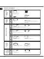
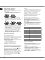
Practical cooking advice
ª
Pressure cooking
Pressure cooker
Frying
Grilling Boiling
Very high-flame
cooking
High-flame
cooking
Medium-flame cookingLow-flame
cooking
Very
low-flame
cooking
•
•
¶
Crêpes Cooking on a high flame and browning
(roasts, steaks, escalopes, fish fillets,
fried eggs)
¶
§
Fast thickening (liquid juices)
Boiling water (pasta, rice, vegetables)
Milk
§
S
Slow thickening (dense juices)
S
¢
Bain-marie cooking Pressure cooking after whistle
¢
£
™
Low-flame cooking (stews)
Reheating dishes
™
¡
Chocolate sauce Keeping food hot

11
GB
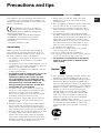
Precautions and tips
! This appliance has been designed and manufactured
in compliance with international safety standards. The
following warnings are provided for safety reasons and
must be read carefully.
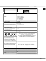
This appliance conforms to the following
European Economic Community directives:
- 2006/95/EEC dated 12/12/06 (Low Voltage) and
subsequent amendments;
- 2004/108/EEC dated 15/12/04 (Electromagnetic
Compatibility) and subsequent amendments;
- 93/68/EEC dated 22/07/93 and subsequent
amendments.
- 1275/2008 stand-by/off mode.
General safety
! Make sure that the air inlet behind the fan grille is
never obstructed. The built-in hob should, in fact, be
provided with suitable ventilation for the cooling of the
electronic components used in the appliance.
• The appliance was designed for domestic use inside
the home and is not intended for commercial or
industrial use.
• The appliance must not be installed outdoors, even in
covered areas. It is extremely dangerous to leave the
appliance exposed to rain and storms.
• Do not touch the appliance when barefoot or with wet
or damp hands and feet.
• The appliance must be used by adults only for the
preparation of food, in accordance with the
instructions outlined in this booklet. Any other
use of the appliance (e.g. for heating the room)
constitutes improper use and is dangerous. The
manufacturer may not be held liable for any
damage resulting from improper, incorrect and
unreasonable use of the appliance.
• The glass ceramic hob is resistant to mechanical
shocks, but it may crack (or even break) if hit with a
sharp object such as a tool. If this happens,
disconnect the appliance from the electricity mains
immediately and contact a Service Centre.
• Ensure that power supply cables of other electrical
appliances do not come into contact with the hot
parts of the hob.
• Remember that the cooking zones remain relatively
hot for at least thirty minutes after they have been
switched off. An indicator light provides a warning
when residual heat is present (
see Start-up and use
).
• Keep any object which could melt away from the hob,
for example plastic and aluminium objects, or
products with a high sugar content. Be especially
careful when using plastic film and aluminium foil or
packaging: if placed on surfaces which are still hot,
they may cause serious damage to the hob.
• Always make sure that pan handles are turned
towards the centre of the hob in order to avoid
accidental burns.
• When unplugging the appliance, always pull the plug
from the mains socket; do not pull on the cable.
• Never perform any cleaning or maintenance work
without having disconnected the appliance from the
electricity mains.
• The appliance should not be operated by people
(including children) with reduced physical, sensory or
mental capacities, by inexperienced individuals or by
anyone who is not familiar with the product. These
individuals should, at the very least, be supervised
by someone who assumes responsibility for their
safety or receive preliminary instructions relating to
the operation of the appliance.
• Do not look at the halogen lamps in the cooking
zones for long if they are present.
• Do not let children play with the appliance.
• Do not place metal objects (knives, spoons, pan lids,
etc.) on the hob as they may become hot..
• The appliance is not intended to be operated by
means of an external timer or separate remote-
control system.
Disposal
• When disposing of packaging material: observe local
legislation so that the packaging may be reused.
• The European Directive 2002/96/EC relating to Waste
Electrical and Electronic Equipment (WEEE) states
that household appliances should not be disposed of
using the normal solid urban waste cycle. Exhausted
appliances should be collected separately in order to
optimise the cost of re-using and recycling the
materials inside the machine, while preventing
potential damage to the atmosphere and to public
health. The crossed-out dustbin is marked on all
products to remind the owner of their obligations
regarding separated waste collection.
For further information relating to the correct disposal
of exhausted household appliances, owners may
contact the public service provided or their local
dealer.

12
GB
Care and maintenance
Switching the appliance off
Disconnect your appliance from the electricity
supply before carrying out any work on it.
Cleaning the appliance
! Do not use abrasive or corrosive detergents (for
example, products in spray cans for cleaning
barbecues and ovens), stain removers, anti-rust
products, powder detergents or sponges with
abrasive surfaces: these may scratch the surface
beyond repair.
! Never use steam cleaners or pressure cleaners on
the appliance.
• It is usually sufficient simply to wash the hob
using a damp sponge and dry it with absorbent
kitchen towel.
• If the hob is particularly dirty, rub it with a special
glass ceramic cleaning product, then rinse well
and dry thoroughly.
• To remove more stubborn dirt, use a suitable
scraper. Remove spills as soon as possible,
without waiting for the appliance to cool, to avoid
residues forming crusty deposits. You can
achieve excellent results by using a rust-proof
steel wire sponge - specifically designed for
glass ceramic surfaces - soaked in soapy water.
• If any plastic or sugary substances are
accidentally melted on the hob, remove them
immediately with the scraper, while the surface is
still hot.
• Once it is clean, the hob may be treated with a
special protective maintenance product: the
invisible film left by this product protects the
surface from drips during cooking. This
maintenance task should be carried out while the
appliance is warm (not hot) or cold.
• Always remember to rinse the appliance well with
clean water and dry it thoroughly: residues can
become encrusted during subsequent cooking
processes.
Stainless steel frame (only in models with outer
frame)
Stainless steel can be marked by hard water which
has been left on the surface for a long time, or by
cleaning products containing phosphorus.
After cleaning, it is advisable to rinse the surface
well and dry it thoroughly. If water is spilt on the
surface, dry it quickly and thoroughly.
! Some hobs have an aluminium frame which is
similar to stainless steel. Do not use any cleaning or
degreasing products which are not suitable for use
with aluminium.
Disassembling the hob
If it is necessary to disassemble the hob:
1. Loosen the screws fixing the alignment springs on
each side.
2. Loosen the screws holding the fixing hooks in
each corner.
3. Take the hob out of its installation cavity.
! Do not attempt to repair the appliance yourself. If
the appliance breaks down, contact a Service
Centre.

13
GB
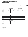
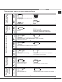
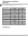
Technical description of
the models
This table provides a model-by-model list of the energy absorption values, type of heating elements and
diameters of each cooking zone.
Hobs
Cooking zone
Back Left
Back Right
Front Left
Front Right
Total power
Power (W)
H 2300
H 1400
H 1200
H 1800
Diameter (mm)
210
160
145
180
6700
Power (W)
HD 2200/1000
H 1400
H 1200
H 1800
Diameter (mm)
210/140
160
145
180
6600
Hobs
Cooking zone
Back Left
Back Right
Front Left
Front Right
Total power
Power (W)
HD 2200/800
H 1400
H 1200
H 1800
Diameter (mm)
210/140
160
145
180
6800
7HKEC 645 D X RU/HA
Hobs
Cooking zone
Back Left
Centre Left
Front Right
Total power
Power (W)
H 1400
HT 2700/1950/1050
H 1800
Diameter (mm)
160
270/210/145
180
5900
Key:
H = single hilight
HD = double hilight
HT = triple hilight
7HKRC 640 B RU/HA
7HKRC 640 X RU/HA
CRC 640 X RU/HA
7HKRC 641 D X RU/HA
7HKRC 641 D B RU/HA
CRC 641 D B RU/HA
7HKRC 631 T RU/HA
CRC 631 T X RU/HA

Руководство по
эксплуатации
Содержание
Монтаж, 15-17
Расположение
Электрическое подключение
Описание изделия, 18-19
Панель управления
Расширяющиеся варочные зоны
Включение и эксплуатация, 20-23
Включение варочной панели
Включение варочных зон
Выключение варочных зон
Функция power
Нагревательные элементы
Программирование продолжительности приготовления
Таймер
Блокировка управлений
Выключение варочной панели
Modalitа Режим «demo»
Практические советы по эксплуатации изделия
Защитные устройства
Практические советы по приготовлению блюд
Предосторожности и рекомендации, 24
Общие требования к безопасности
Утилизация
Техническое обслуживание и уход, 25
Обесточивание изделия
Чистка изделия
Порядок демонтажа варочной панели
Техническое описание моделеи, 26
ВАРОЧНАЯ ПАНЕЛЬ
RS
RS
Русский, 14
English,1
GB
7HKRC 640 B RU/HA
7HKRC 640 X RU/HA
7HKRC 641 D X RU/HA
7HKEC 645 D X RU/HA
7HKRC 631 T RU/HA
7HKRC 641 D B RU/HA
CRC 640 X RU/HA
CRC 641 DB RU/HA
CRC 631 TX RU/HA

15
RS
Монтаж
! Важно сохранить данное руководство для его
последующих консультации. В случае продажи,
передачи изделия или при переезде на новое
место жительства необходимо проверить, чтобы
руководство оставалось вместе с изделием, для
того чтобы его новыи владелец мог ознакомиться
с правилами эксплуатации и с соответствующими
предупреждениями.
! Внимательно прочитаите инструкции: в них
содержатся важные сведения о монтаже изделия,
его эксплуатации и безопасности.
Расположение
! Не разрешаите детям играть с упаковочными
материалами. Упаковка должна быть уничтожена в
соответствии с правилами сбора мусора (см.
Предосторожности и рекомендации).
! Монтаж изделия производится в соответствии с
данными инструкциями квалифицированными
специалистами. Неправильный монтаж изделия
может стать причиной повреждения имущества и
причинить ущерб людям и домашним животным.
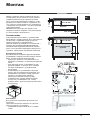
Встроенный монтаж
Для обеспечения исправного функционирования
встраиваемого изделия кухонный модуль должен
иметь соответствующие характеристики:
• поверхность кухонного топа должна быть из
материала, устойчивого к температуре примерно
100°C;
• если варочная панель устанавливается над
духовым шкафом, он должен быть оснащен
системой охлаждения с принудительной
вентиляцией.
• не рекомендуется устанавливать варочную
панель над посудомоечными машинами: при
необходимости установите между варочной
панелью и посудомоечной машиной
герметичную разделительную вставку;
• в зависимости от модели варочной панели,
которую вы устанавливаете (см. схемы),
размеры ниши в кухонном модуле должны быть
следующими:
Вентиляция
Для обеспечения надлежащей вентиляции и во
избежание
перегрева прилегающих поверхностеи варочная
панель должна быть установлена:
• на минимальном расстоянии 40 мм от задней
стенки;
5 mm
min. 20 mm
min. 20 mm
min. 40 mm
Ящиком
5 mm
min. 40 mm
Вентилированная
духовка
560 +/- 1
490 +/- 1
48
590
520

16
RS
• между проемом под варочную панель и
расположенным снизу кухонным элементом
должно быть расстояние не менее 20 мм.
• Кухонные элементы, расположенные рядом с
кухонной плитой, высота которых превышает уровень
варочной панели, должны находиться на расстояние
не менее 600 мм от края варочной панели.
Крепление
Изделие должно быть установлено на идеально
ровнои поверхности.
Возможные деформации, вызванные
неправильным креплением, могут привести к
изменениям характеристик и эксплуатационных
качеств варочнои панели.
Длина регуляционного винта крепежных крюков
регулируется перед началом монтажа по толщине
кухонного топа:
• толщина 30 мм: длина винта 17,5 мм;
• толщина 40 мм: длина винта 7,5 мм;
Порядок крепления изделия:
1. При помощи коротких тупых шурупов
привинтите 4 центровочные пружины в отверстиях,
расположенных по бокам варочнои панели;
2. Вставьте варочную панель в проем в кухонном
модуле, выровняите и слегка нажмите в центр
вплодь до идеального прилегания варочнои
панели к поверхности кухонного топа.
3. для варочных панелеи с боковыми профилями:
вставив варочную панели в нишу кухонного
модуля, вставьте 4 крепежных крюка (каждыи со
своим штифтом) по нижнему периметру варочнои
панели, закручивая их длинными острыми болтами
до тех пор, пока стекло не будет плотно прилегать
к кухонному топу.
! Важно, чтобы шурупы центровочных пружин
оставались доступными.
! В соответствии с правилами безопасности после
установки изделия в кухонныи модуль должна
быть исключена возможность касания к
электрическими частями.
! Все защитные элементы должны быть
закреплены таким образом, чтобы их можно было
снять только при помощи специального
инструмента.
Электрическое подключение
! Электрическое подключение варочнои панели и
возможного встраиваемого духового шкафа
должно выполняться раздельно по причинам
безопасности, а так же для легкого съема
духового шкафа.
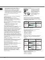
Клеммная колодка
В нижнеи части изделие
оснащено колодкои для
подсоединения разных
видов электропитания
(рисунок приводится для
примера и может не
соответствовать модели
вашего изделия).
Монофазное соединение
Варочная панель оснащена сетевым кабелем,
рассчитанным на монофазное электропитание.
Подсоедините провода в соответствии с таблицеи
и приведенным ниже схемам:
Типовое
напряжение
и частота сети
Электрический провод Подсоединение
проводов
230-240V 1+N ~
220-240V 1+N ~
50/60 Hz
: желто-зеленый;
N: 2 синий провода
вместе на
L: коричневый
вместе с черным
Другие типы соединений
Если электропроводка соответствует однои из
следующих характеристик:
Типовое напряжение и частота сети
• 400В - 2+N ~ 50/60 Гц
• 220-240В 3 ~ 50/60 Гц
• 230-240B 3 ~ 50/60 Hz
• 400В - 2+2N ~ 50/60 Гц
Разделите провода и подсоедините проводники в
соответствии с таблицеи и приведенным ниже
схемам:
Типовое
напряжение
и частота сети
Электрический провод Подсоединение
проводов
400V - 2+N ~
50/60 Hz
230-240V 3 ~
220-240V 3 ~
50/60 Hz
: желто-зеленый;
N: 2 синий провода
вместе на
L1: черный
L2: коричневый
400V - 2+2N ~
50/60 Hz
: желто-зеленый;
N1: синий
N2: синий
L1: черный
L2: коричневый
Если электропроводка соответствует однои из
следующих характеристик:
Типовое напряжение и частота сети
• 400В 3 - N ~ 50/60 Гц
выполните следующее:

17
RS
! Возможныи прилагающиися сетевои кабель
нельзя использовать для такого типа монтажа.
1. Используите надлежащии сетевои кабель типа
H05RR-F или с большим значением, надлежащего
размера (сечение кабеля: 25 мм).
2. При помощи отвертки поднимите язычки
крышки клеммнои колодки и откроите ее (см.
изображение клеммнои колодки).
3. Отвинтите прижимнои винт провода и винты
зажимов, соответствующих типу необходимого
соединения, затем установите соединительные
перемычки согласно таблице и приведенным ниже
схемам.
4. Расположите проводники согласно таблице и
приведенным ниже схемам и подсоедините их, до
упора закрутив все винты зажимов.
Типовое напряжение
и частота сети
Электропитание Зажимная коробка
400V 3-N ~
50/60 Hz
Трехфазный 400
5. Зафиксируите сетевои кабель в специальном
кабельном сальнике и закроите крышку.
Трехфазное 400
Подсоединение сетевого кабеля изделия к
сети электропитания
В случае прямого подключения изделия к сети
необходимо установить между изделием и
электрическои сетью многополярныи
разъединитель с минимальным расстоянием
между контактами 3 мм.
! Электромонтер несет ответственность за
правильное подключение изделия к электрическои
сети и за соблюдение правил безопасности.
Перед осуществлением электрического
подсоединения необходимо проверить
следующее:
• сетевая розетка должна быть соединена с
заземлением и соответствовать нормативам;
• сетевая розетка должна быть расчитана на
максимальную потребляемую мощность
изделия, указанную на паспортнои табличке с
техническими характеристиками;
• напряжение и частота тока сети должны
соответствовать электрическим данным
изделия;
• сетевая розетка должна быть совместима со
штепсельнои вилкои изделия. В противном
случае замените розетку или вилку; не
используите удлинители или троиники.
! Изделие должно быть установлено таким
образом, чтобы сетевои кабель и сетевая розетка
были легко доступны.
! Сетевои кабель изделия не должен быть согнут
или сжат.
! Регулярно проверяите состояние сетевого кабеля
и при необходимости поручаите его замену только
уполномоченным техникам.
! Производитель не несет ответственности за
последствия несоблюдения перечисленных
выше требовании.
! Категорически запрещается отсоединять и не
заменять сетевой кабель. В случае отсоединения
или замены сетевого кабеля гарантия на изделие
аннулируется, равно как и маркировка ЕС.
Компания INDESIT снимает с себя всякую
ответственность за несчастные случаи или ущерб,
вызванный отсоединением или заменой
оригинального сетевого кабеля. Допускается
замена только на оригинальный сетевой кабель,
выполняемая техником, уполномоченным
Компанией INDESIT.
1
2
3
5
4

18
RS
Описание изделия
Панель управления
• Кнопка УВЕЛИЧЕНИЕ МОЩНОСТИ служит для
включения варочнои зоны и регуляции
мощности нагрева (см. Включение и
эксплуатация).
• Кнопка УМЕНЬШЕНИЕ МОЩНОСТИ служит для
регуляции мощности и выключения варочнои
зоны (см. Включение и эксплуатация).
• Индикатор ВЫБРАННАЯ ВАРОЧНАЯ ЗОНА
показывает, что соответствующая варочная
зона была выбрана и следовательно возможно
произвести настроики ее функции.
• Кнопка ВЫБОР ВАРОЧНОИ ЗОНЫ служит для
выбора нужнои варочнои зоны.
• Индикатор МОЩНОСТЬ: показывает уровень
нагрева.
• Кнопка ON/OFF (ВКЛ./ВЫКЛ.) служит для
включения и выключения изделия.
• Индикатор ON/OFF (ВКЛ./ВЫКЛ.): показывает
состояние изделия, включено или выключено.
• Кнопка ТАИМЕР ПРОГРАММИРОВАНИЯ*
служит для настроики продолжительности
приготовления (см. Включение и эксплуатация).
• Дисплеи ТАИМЕРА ПРОГРАММИРОВАНИЯ*:
показывает различные настроики
программирования (см. Включение и
эксплуатация).
• Индикаторы ЗАПРОГРАММИРОВАННЫЕ
ВАРОЧНЫЕ ЗОНЫ*: показывают варочные
зоны после запуска программирования ( см.
Включение и эксплуатация).
• Кнопка БЛОКИРОВКА УПРАВЛЕНИИ служит
для защиты управлении варочнои панели от
случаиных измнении (см. Включение и
эксплуатация).
• Индикатор УПРАВЛЕНИЯ ЗАБЛОКИРОВАНЫ
показывает, что управления заблокированы (
см. Включение и эксплуатация).
• Индикатор ТАИМЕР* показывает, что таимер
включен
! Данное изделие отвечает требованиям новой
Европейской Директивы по ограничению
энергопотребления в режиме энергосбережения.
Если в течение 2-х минут не производится
никаких действий после выключения
индикаторов остаточного тепла и вентилятора
(если они присутствуют), изделие
автоматически переходит в режим «ВЫКЛ.».
Возврат изделия в рабочий режим
производится кнопкой ВКЛ./ВЫКЛ.
Панель управления, описание которои приводится ниже, служит только в качестве примера: она может не в
точности соответствовать Вашеи модели.
*
Имеется только в некоторых моделях.

19
RS
Расширяющиеся варочные зоны
В некоторых моделях имеются расширяющиеся варочные зоны. Ниже приводится описание
соответствующих управлении, имеющихся только в моделях, оснащенных этими функциями.
Круглая расширяющаяся варочная зона
• Кнопка ВКЛЮЧЕНИЕ ДВОИНОИ ВАРОЧНОИ
ЗОНЫ служит для включения двоинои конфорки
(см. Включение и эксплуатация).
• Индикатор ДВОИНАЯ ВАРОЧНАЯ ЗОНА
ВКЛЮЧЕНА: показывает, что двоиная варочная
зона включена.
• Кнопка ВКЛЮЧЕНИЕ ТРОИНОИ ВАРОЧНОИ
ЗОНЫ служит для включения троинои конфорки
(см. Включение и эксплуатация).
• Индикатор ТРОИНАЯ ВАРОЧНАЯ ЗОНА
ВКЛЮЧЕНА: показывает, что троиная варочная
зона включена.

20
RS
Включение и
эксплуатация
! На стекляннои поверхности варочнои панели
могут быть видны сальные следы от клея,
нанесенного на прокладки Перед началом
эксплуатации изделия следует удалить следы
клея при помощи специального неабразивного
моющего средства. В первые часы работы вы
можете почувствовать запах жженои резины,
которыи быстро пропадает.
! Через несколко секунд после подсоединения
варочнои панели к сети электропитания
включается короткии звуковои сигнал. Только
после этого можно включить варочную панель.
! При длительном нажатии на кнопки - и +
происходит быстрая смена уровнеи мощности и
минут таимера.
Включение варочной панели
Включите варочную панель, нажав кнопку
примерно на одну секунду.
Включение варочных зон
Каждая зона варочнои панели включается при
помощи кнопки
и регулятора мощности,
состоящего из двоинои кнопки
- и +.
• Для включения однои из варочных зон нажмите
соответствующую кнопку и настроите нужную
мощность при помощи кнопок
- и +.
Выключение варочных зон
Для отключения варочнои зоны выберите ее при
помощи соответствующеи кнопки
и затем:
• Нажмите кнопку
-: мощность варочнои зоны
постепенно понизится вплоть до выключения.
Функция power
Для ускорения нагрева варочных зон можно
использовать функцию power. Включите и
настроите мощность нужнои варочнои зоны
,
как описано в предыдущем параграфе. Нажмите и
держите нажатои не менее 2 секунд кнопку
выбора нужнои варочнои зоны
. На дисплее
попеременно будет показываться индикатор
мощности, буква «Р» и ранее заданное значение
уровня мощности в течение всего времени,
необходимого для достижения заданного уровня
мощности. По достижении заданного уровня
мощности на дисплее опять будет показываться
заданныи уровень мощности. Для отмены этои
функции нажмите и держите нажатои не менее 2
секунд кнопку выбора варочнои зоны, для которои
была включена функция
, или же задаите
другои уровень мощности при помощи кнопок
- и
+.
Нагревательные элементы
В зависимости от модели вашеи варочнои панели
она может быть укомплектована нагревательными
элементами двух видов: галогенными и
спиральными.
Галогенные элементы передают тепло
посредством излучения внутреннеи галогеннои
лампы.
Такои принцип нагревания по своим
характеристикам аналогичен типичным газовым
конфоркам: быстрая реакция на управление,
мгновенная визуализация мощности.
Спиральныи нагревательныи элемент состоит из
нескольких спиральных сопротивлении,
обеспечивающих однородное распределение
тепла по всему дну посуды для оптимального
приготовления любых блюд на медленном огне:
рагу, соусы или для разогревания готовых блюд.
Программирование
продолжительности приготовления
! Можно одновременно настроить все варочные
зоны на приготовление от 1 до 99 минут.
1. Выбрать варочную зону при помощи
соответствующеи кнопки выбора.
2. Отрегулируйте уровень мощности варочной
зоны.
3. Нажать кнопку программирования
.
4. Настроить нужную продолжительность
приготовления при помощи кнопок
- и +.
5. Подтвердить настройки при помощи кнопки
,
или переключение происходит автоматически
через 10 секунды.
Обратный отсчет таймера начинается сразу же. По
завершении заданного приготовления раздается
звуковой сигнал (в течение 1 минуты), и варочная
зона выключается.
Повторите вышеописанную операцию для каждой
варочной зоны, которую требуется
запрограммировать.
Страница загружается ...
Страница загружается ...
Страница загружается ...
Страница загружается ...
Страница загружается ...
Страница загружается ...
Страница загружается ...
Страница загружается ...
-
 1
1
-
 2
2
-
 3
3
-
 4
4
-
 5
5
-
 6
6
-
 7
7
-
 8
8
-
 9
9
-
 10
10
-
 11
11
-
 12
12
-
 13
13
-
 14
14
-
 15
15
-
 16
16
-
 17
17
-
 18
18
-
 19
19
-
 20
20
-
 21
21
-
 22
22
-
 23
23
-
 24
24
-
 25
25
-
 26
26
-
 27
27
-
 28
28


Hotpoint Ariston 7HKEC 645 D X RU/HA Руководство пользователя
- Категория
- Кухонные плиты (варочные панели)
- Тип
- Руководство пользователя
Задайте вопрос, и я найду ответ в документе
Поиск информации в документе стал проще с помощью ИИ
на других языках
Похожие модели бренда
Модели других брендов
-
Whirlpool 7HKRC 631 T RU/HA Руководство пользователя
-
Hotpoint-Ariston RC631 TIRFH Руководство пользователя
-
-
-
Indesit 7HKRM 641 D X RU/HA Руководство пользователя
-
-
-
Whirlpool NRO 642 D Z Инструкция по эксплуатации
-
-