Tripp Lite 8 and 10kVA Parallel PDUs Инструкция по применению
- Категория
- Источники бесперебойного питания (UPS)
- Тип
- Инструкция по применению

1
Owner’s Manual
SmartOnline
®
16 & 20kVA UPS
with N+1 Configuration Options
Models: SU16KRT, SU16KRT-1TF, SU16KRT8, SU16KRTG, SU16KRTHW, SU20KRT,
SU20KRT-1TF, SU20KRT8, SU20KRTG, SU20KRTHW, SU20KRTHWTFASSM
Introduction 2
Important Safety Warnings 3
Mounting 4
Features 6
Connection 8
Manual Bypass Operation 10
Storage & Service 12
Warranty & Product Registration 12
Español 13
Français 25
Русский 37
PROTECT YOUR INVESTMENT!
Register your product for quicker service and ultimate peace of mind.
You could also win an ISOBAR6ULTRA surge protector—a $100 value!
www.tripplite.com/warranty
1111 W. 35th Street, Chicago, IL 60609 USA • www.tripplite.com/support
Copyright © 2018 Tripp Lite. All rights reserved.

2
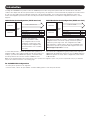
10kVA UPS
Loads 10kVA and lower
Parallel
PDU
10kVA UPS
10kVA UPS
Loads 10-20kVA
Parallel
PDU
10kVA UPS
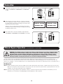
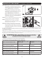
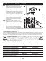
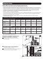
Introduction
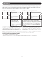
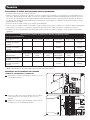
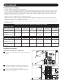
Your Tripp Lite 16/20kVA UPS system includes two 8/10kVA power modules along with a parallel PDU and communications cable that
combines the output of the two UPS power modules to directly power your equipment. Your UPS automatically supports N+1 fault tolerance
at load levels up to 50% and non-redundant operation at loads greater than 50%. The included parallel PDU with bypass switch also
enables hot-swappable replacement of either or both power modules without downtime. For additional configuration assistance, contact
Tripp Lite.
10kVA Redundant Configuration (10kVA max load) 20kVA Non-Redundant Configuration (20kVA max load)
Redundant Operation YES
Fault-Tolerance YES
Hot-Swappable UPS Replacement YES
Increased Capacity NO
Redundant Operation NO
Fault-Tolerance NO
Hot-Swappable UPS Replacement YES
Increased Capacity YES
When two UPS systems are
loaded to a maximum of 50%,
your configuration will receive full
redundancy—fault-tolerance with
full support for hot-swappable UPS
replacement in the case of sudden
UPS failure.
When two UPS systems are loaded to a maximum of 100%, your
configuration will receive the full capacity of both UPS systems
combined to power larger loads. This configuration does NOT
carry redundancy or fault-tolerance options. Hot-swappable UPS
replacement is possible if you put the PDU in bypass mode (See
“Manual Bypass Operation” Section).
To ensure fault-tolerance, load the two parallel UPS systems to a
maximum of 50% of the combined rating for both UPS systems. For
example, if you have two 10kVA UPS systems, you will have fault-
tolerant operation if the load level remains at 10kVA or lower.
Your can use this configuration to grow your UPS power capacity to
16kVA (when two 8kVA UPS systems are used) or 20kVA (when two
10kVA UPS systems are used). In this configuration, fault-tolerance
is NOT available.
For 16/20KVA UPS Configurations
• Economy-mode operation is not supported
• For best results, connect an equal number of external battery packs to each UPS power module.
Note: Use the included 8/10kVA power module manual for UPS operation and configuration options once you have completed the setup of your 16/20kVA
UPS per the installation information on the following pages.

3
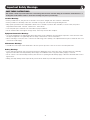
Important Safety Warnings
Location Warnings
• Install your PDU indoors, away from excess moisture or heat, direct sunlight, dust and conductive contaminants.
• Install your PDU in a structurally sound area. Your PDU is heavy; take care when moving and lifting the unit.
• Only operate your PDU at indoor temperatures between 32° F and 104° F (between 0° C and 40° C). For best results, keep indoor
temperatures between 62° F and 84° F (between 17° C and 29° C).
• Leave adequate space around all sides of the PDU for proper ventilation.
• Do not install the PDU near magnetic storage media, as this may result in data corruption.
Equipment Connection Warnings
• Use of this equipment in life support applications where failure of this equipment can reasonably be expected to cause the failure of the
life support equipment or to significantly affect its safety or effectiveness is not recommended.
• When connecting to a UPS, the UPS is connected to a DC energy source (battery). The output terminals may be live when the UPS is not
connected to an AC supply.
Maintenance Warnings
• Your PDU does not require routine maintenance. Do not open for any reason. There are no user-serviceable parts inside.
Battery Warnings
• Service and repair should be done only by trained personnel. During any service work to the UPS, it should be turned off or manually
bypassed via the PDU. Note that potentially lethal voltages exist within this unit as long as the battery supply is connected.
• Do not connect or disconnect battery module(s) while the UPS is operating from the battery supply or when the detachable PDU is not in
bypass mode.
• During “hot-swap” battery module replacement your UPS will be unable to provide battery backup in the event of a blackout.
SAVE THESE INSTRUCTIONS.
This manual contains important instructions and warnings that should be followed during the installation and maintenance of
all Tripp Lite Parallel PDUs. Failure to heed these warnings may affect your warranty.

4
2
1
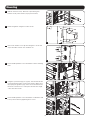
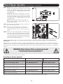
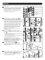
Mounting
UPS Power Module 1
Battery Module 1
UPS Power Module 2
Battery Module 2
D
F
E
G
C
C
B
A
B
A
3
3
4
5
C
C
B
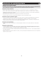
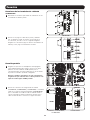
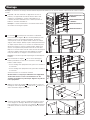
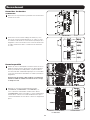
Note: It is recommended that the following mounting instructions only be used in standard rack enclosures and 4-Post Open Frame Racks.
1
It is important to note that in order to accommodate paralleling
applications, equipment must be mounted in the following order
(see diagram): UPS Power Module 1, UPS Power Module 2,
Battery Module 1 and Battery Module 2.
Note: The power module and battery module must be installed in
separate shelves.
2
The included plastic pegs
A
will temporarily support the empty
rackmount shelves
B
while you install the permanent mounting
hardware. Insert a peg near the center of the front and rear
bracket of each shelf as shown. (Each front bracket has 6 holes
and each rear bracket has 3 holes.) The pegs will snap into
place.
After installing the pegs, expand each shelf to match the depth
of your rack rails. The pegs will fit through the square holes in the
rack rails to support the shelves. Refer to the rack unit labels to
confirm that the shelves are level in all directions.
Note: The support ledge of each shelf must face inward.
3
Secure the shelves
B
to the mounting rails permanently using
the included screws and cup washers
C
as shown.
• For 2U equipment mounting, place 4 screws total at the front
and 4 screws total at the back.
• For 3U equipment mounting, place 6 screws total at the front
and 4 screws total at the back.
Tighten all screws before proceeding.
Warning: Do not attempt to install your equipment until
you have inserted and tightened the required screws. The
plastic pegs will not support the weight of your equipment.
4
Attach mounting ears
D
to the front mounting holes of your
equipment
E
using the screws provided
F
. The ears should face
forward.
5
Using an assistant, lift your equipment and slide it onto the
mounting shelves. Attach your equipment to the rack by passing
the screws, nuts and washers (user-provided)
G
through its
mounting ears and into the rack rails.

5
6
10
11
8
7
9
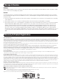
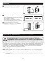
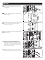
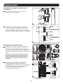
Mounting
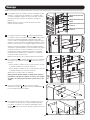
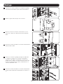
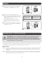
6
With the included screws, attach the 4 placement guide
brackets to the power modules (2 per power module).
7
Install wiring bustle using the included screws.
8
Remove the terminal covers by unscrewing the 2 screws and
expose the PDU contacts. Save for future use.
9
Connect Battery Module 2 to Power Module 2 before installing
PDU.
10
Using the 4 placement pegs as a guide, slide the PDU into the
placement guide brackets on the power modules. When lined
up properly, the guidance pegs on the rear of the PDU should
fit into the clearance holes on the power modules and a tight
connection will be made.
11
Connect Battery Module 1 to Power Module 1. Attach the PDU
to the power modules by tightening the 4 screws.

6
1
1
6
5
4
4
4
7 7
22
5 5
8 88 8
3 3
3
11
12
10
12
13
13
4
7
2
5
9
9
3
1
2
1
14
14
14
14
14
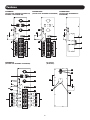
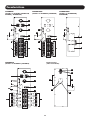
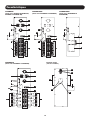
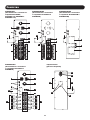
Features
SUPDMB20K
(Included with SU16KRT, SU16KRT-1TF,
SU20KRT and SU20KRT-1TF)
SUPDMB20KHW
(Included with SU16KRTHW &
SU20KRTHW)
SUPDMB20KIEC
(Included with SU16KRTG & SU20KRTG)
Back Panel
(All models)
SUPDMB20K8
(Included with SU16KRT8 & SU20KRT8)

7
Features
1
L6-30R Output Receptacles: Accept direct plug-in connection of L6-30P equipment plugs.
2
Output Breakers (30 Amp): One double-pole circuit breaker provides bypass for the parallel system to the load.
3
Parallel Cable Connectors: For UPS communication in parallel.
4
Maintenance Switch (100 Amp): Controls maintenance to the power module.
5
Utility Input Terminal Block: Use this terminal to connect your power module to utility power or to the transformer module. Unscrew
and remove the cover over the block for access.
6
Equipment Output Terminal Block (SUPDMB20KHW only): Use this terminal to connect your power module to your equipment or to
the transformer module. Unscrew and remove the cover over the block for access.
7
Output Breakers (20 Amp): One double-pole circuit breaker provides bypass for the parallel system to the load.
8
IEC-320-C19 Output Receptacles: Accept direct plug-in connection of IEC-320-C19 equipment plugs.
9
L6-20R Output Receptacles: Accept direct plug-in connection of locking L6-20P equipment plugs
10
PDU Connection Access Covers: Remove to make connections between the PDU and power modules.
11
PDU Input Terminal Block: Use these terminals to connect the PDU to the power module.
12
PDU Guidance Pegs: Found on the side of the PDU to help guide PDU installation placement. Used in conjunction with PDU placement
guide brackets (see Mounting section for more details).
13
PDU Guidance Posts: Found on the back panel of the PDU to help guide PDU installation placement. See “Mounting” section for more
details.
14
Wiring Bustle: Must be installed prior to mounting PDU. See Mounting section for more details.

8
1
2
N(L2)
GROUND
L(L1)
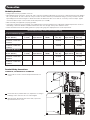
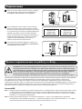
Connection
Terminal Wiring Connections
SUPDMB20K, SUPDMB20KIEC & SUPDMB20K8
1
Unscrew the 2 screws to remove the Input Terminal Access
covers.
2
Connect the N (L2), Ground and L (L1) input wires according to
markings on the connectors as seen in the diagram.
3
After input wire attachments have been made, replace the
Input Terminal Access covers.
Hardwiring Cautions
• Wiring must be done by a qualified electrician.
• When making wiring connections, observe the cable connection regulations appropriate to your area [e.g. National Electrical Code (NEC) in
the U.S.] at all times. Be sure to install an easily accessible disconnect switch in your installation wiring so you may cut off the UPS’s AC
input during fires and other emergencies. Ensure that cables are fitted with cable sleeves and are secured by connector clamps. Tighten
connections with a torque of not less than 24-28 inch-pounds (2.7-3.2 NM).
• Make sure that your equipment is properly grounded.
• Using cables of improper size may damage your equipment and cause fire hazards. Choose appropriate cabling and protection circuits to
make wiring connections. Ground conductors must be the same size and type as the power conductors used.
• Refer to National Electrical Code (NEC) guidelines for proper wire gauge and output protection circuit requirements.
Input & Output* Ratings and Recommended Wire Sizing
For N+1 Redundant Operation
Models (Bundles)
Input Voltage
(L-L/L-N)
Max Rated
Input Current
Input Service
OCPD**
Typical Input
Wire Size
Max Rated
Output Current
Typical Output
Wire Size
SU16KRT, SU16KRT-1TF,
SU16KRTG, SU16KRTHW,
SU16KRT8
200V-240V 46A 50A 10 mm
2
(#8 AWG)
40A 10 mm
2
(#8 AWG)
SU20KRT, SU20KRT-1TF,
SU20KRTG, SU20KRTHW,
SU20KRT8
200V-240V 56A 60A 16 mm
2
(#6 AWG)
50A 10 mm
2
(#8 AWG)
For Capacity Operation
Models (Bundles)
Input Voltage
(L-L/L-N)
Max Rated
Input Current
Input Service
OCPD**
Typical Input
Wire Size
Max Rated
Output Current
Typical Output
Wire Size
SU16KRT, SU16KRT-1TF,
SU16KRTG, SU16KRTHW,
SU16KRT8
200V-240V 92A 100A 35 mm
2
(#3 AWG)
80A 25 mm
2
(#4 AWG)
SU20KRT, SU20KRT-1TF,
SU20KRTG, SU20KRTHW,
SU20KRT8
200V-240V 112A 125A 50 mm
2
(#1 AWG)
100A 35 mm
2
(#3 AWG)
* Input - hardwired; Output - hardwired or receptacles/outlets ** OCPD - Overcurrent protective device

9
1
2
N(L2)
N(L2)
GROUND
GROUND
L(L1)
L(L1)
ACC.SLOT
RS-232
ARALLEL
EPO
SW
ACC.SLOT
RS-232
PA LLEL
EPO
SW
CAUTION:
CAUTION:
DO NOT DISCONNE CT DO NOT DI SCONNECT
1
2
INPUT
INPUT
OUTPUT
OUTPUT
SUPDMB20K, SUPDMB20KIEC,
SUPDMB20K8
SUPDMB20KHW
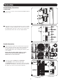
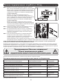
Connection
Terminal Wiring Connections
SUPDMB20KHW
1
Unscrew the 2 screws to remove the Input and Output Terminal
Access covers.
2
Connect the 2 sets of N (L2), Ground and L (L1) wires (1 Input,
1 Output) according to markings on the connectors as seen in
the diagram below. Be sure to connect one set of wires to the
input terminals and the other set to the output terminals.
Parallel Connection
1
Being sure that all switches are off and all units are powered
down, connect the 2 parallel cables. Both will originate from
the parallel PDU with 1 connecting to the primary power
module and the other to the secondary power module. (Refer
to the diagram.)
Ensure that each of the parallel cables is securely
attached to the PDU and UPS by tightening the
thumbscrews on each connection.
2
Connect the input (SUPDMB20K, SUPDMB20KIEC
& SUPDMB20K8), and/or hardwired input/output
(SUPDMB20KHW) AC power connections located on the PDU.
The AC input cord attaches to the facility’s AC source while the
AC output cord connects to the intended equipment.

10
OFF
OFF
ON
ON
3
4
5
PARALLEL : MASTER
00.00kVA / 000%
PARALLEL : SLAVE
00.00kVA / 000%
Manual Bypass Operation (for UPS maintenance or replacement)
WARNING! For qualified service personnel only. Failure to follow the bypass procedure completely will not
adequately power down the UPS, resulting in the continued risk of death or injury from potential contact
with high voltage. The UPS and detachable PDU are extremely heavy. This procedure requires several
people to perform. Please read the procedure completely before proceeding. Failure to follow the UPS
removal procedure correctly may result in a loss of power to the protected load.
The UPS system includes an independent, detachable PDU with a Maintenance Breaker Switch. This switch allows qualified service
personnel to remove the detachable PDU from the UPS for routine maintenance without disrupting power to connected loads. While this
switch is set to “BYPASS”, connected equipment will receive unfiltered AC mains power. However, equipment will not receive battery power in
the event of a blackout.
Connection
3
Power ON the primary power module, being sure that all output
breakers (SUPDMB20K, SUPDMB20KIEC & SUPDMB20K8)
are OFF.
4
After primary power module start-up is complete, power ON
the secondary power module. The UPS systems will self detect
the Parallel Mode and show the following screen shots for the
master and slave power modules:
When the unit is in Parallel Mode the primary power module
will display “Parallel: Master” and the secondary power module
will display “Parallel: Slave”.
5
Once Parallel Mode is detected, turn ON all output breakers
(SUPDMB20K, SUPDMB20KIEC & SUPDMB20K8) on the PDU.
UPS Removal
STEP 1. Disable PowerAlert and disconnect the SNMP, serial or USB communication cables from the communication ports on the UPS. Do
NOT remove the parallel cable at this point. A disconnection of the cable before the power module is properly shut down can result
in multiple error messages depending on your configuration.
STEP 2. Before proceeding, determine your maintenance status (i.e. which UPS system requires maintenance and whether you are in
Redundancy or Power Mode per the Output/Bypass Breaker Operation chart on page 9).

11
3C
5
The UPS power/battery module is now safely powered down and it can be detached from the PDU to perform maintenance/
replacement.
During this process, ensure that each section is properly supported after they are separated. If the sections are detached in a rackmount
application, be sure that each section remains adequately supported by the UPS system’s rackmount rails. If the sections are detached in a
tower application, be sure that the PDU is supported by the UPS system’s tower feet. Adjust the tower feet so they are as close together as
possible.
WARNING! High Voltage! Risk of electrical shock!
Warning: Use extreme caution when handling the PDU.
Do not allow the contacts to touch any surface.
To reattach the PDU, reverse the process listed above.
Output/Bypass Breaker Operation
Output Status (Normal Operation) Parallel PDU Output Breakers Maintenance Bypass Breaker
Output coming from both UPS systems. ON OFF
Output Status (Redundancy Mode) Parallel PDU Output Breakers Maintenance Bypass Breaker
Output coming from Primary UPS. Secondary UPS
needs repair. (Refer to Step 3, Part A.)
ON OFF
Output coming from Secondary UPS. Primary UPS
needs repair. (Refer to Step 3, Part B.)
ON OFF
Output Status (Power Mode) Parallel PDU Output Breakers Maintenance Bypass Breaker
Primary and Secondary UPS output coming from
Bypass. (Refer to Step 3, Part C.)
ON ON
Note: Units will operate in Redundancy Mode up to 8 or 10kVA and switch to Power Mode at loads greater than 8 or 10kVA.
Manual Bypass Operation (for UPS maintenance or replacement)
STEP 3. Part A: When the output is coming from the Primary UPS
and the Secondary UPS needs repair, press the Secondary
UPS system’s OFF button, if the UPS is powered, until you
hear a beep and see a “STANDBY MODE” message shown
in the LCD display.
Part B: When the output is coming from the Secondary
UPS and the Primary UPS needs repair, press the Primary
UPS system’s OFF button, if the UPS is powered, until you
hear a beep and see a “STANDBY MODE” message shown
in the LCD display.
Part C: When both power modules show output is in
Bypass, set the Maintenance Breaker Switch to the ON
position before servicing.
STEP 4. Disconnect any external battery module(s) from the UPS
power module being serviced.
STEP 5. At the rear of the UPS being serviced, remove the 2
screws that secure the PDU to the power module. If
both power modules are in need of service, remove all 4
screws.
STEP 6. Remove the rackmounting hardware from the front panel
of the UPS. Using an assistant at each end, carefully pull
the power module away from the PDU, being careful not
to disconnect the parallel cable. Once the power module
is pulled from the PDU and powers down, disconnect the
parallel cable from the power module.

12
Storage & Service
Storage
Before storing your PDU, be sure all connections have been disconnected and all breakers are turned OFF. Also replace any input or output
access covers so as not to damage any contacts.
Service
Your Tripp Lite product is covered by the warranty described in this manual. A variety of Extended Warranty and On-Site Service Programs
are also available from Tripp Lite. For more information on service, visit www.tripplite.com/support. Before returning your product for service,
follow these steps:
1. Review the installation and operation procedures in this manual to insure that the service problem does not originate from a misreading
of the instructions.
2. If the problem continues, do not contact or return the product to the dealer. Instead, visit www.tripplite.com/support.
3. If the problem requires service, visit www.tripplite.com/support and click the Product Returns link. From here you can request a Returned
Material Authorization (RMA) number, which is required for service. This simple on-line form will ask for your unit’s model and serial
numbers, along with other general purchaser information. The RMA number, along with shipping instructions will be emailed to you.
Any damages (direct, indirect, special or consequential) to the product incurred during shipment to Tripp Lite or an authorized Tripp
Lite service center is not covered under warranty. Products shipped to Tripp Lite or an authorized Tripp Lite service center must have
transportation charges prepaid. Mark the RMA number on the outside of the package. If the product is within its warranty period, enclose
a copy of your sales receipt. Return the product for service using an insured carrier to the address given to you when you request the
RMA.
Warranty & Product Registration
2-Year Limited Warranty
TRIPP LITE warrants its products to be free from defects in materials and workmanship for a period of two years from the date of initial purchase. To obtain service under this
warranty, you must call TRIPP LITE or an authorized TRIPP LITE service center. Products must be returned to TRIPP LITE or an authorized TRIPP LITE service center with transportation
charges prepaid and must be accompanied by a brief description of the problem encountered and proof of date and place of purchase. This warranty does not apply to equipment
which has been damaged by accident, negligence or misapplication or has been altered or modified in any way. This warranty applies only to the original purchaser who must have
properly registered the product within 10 days of purchase.
The warranties of all TRIPP LITE surge suppressors are null and void if they have been connected to the output of any UPS system. The warranties of all TRIPP LITE UPS Systems are
null and void if a surge suppressor has been connected to its output receptacles.
EXCEPT AS PROVIDED HEREIN, TRIPP LITE MAKES NO WARRANTIES, EXPRESS OR IMPLIED, INCLUDING WARRANTIES OF MERCHANTABILITY AND FITNESS FOR A PARTICULAR
PURPOSE. Some states do not permit limitation or exclusion of implied warranties; therefore, the aforesaid limitation(s) or exclusion(s) may not apply to the purchaser.
EXCEPT AS PROVIDED ABOVE, IN NO EVENT WILL TRIPP LITE BE LIABLE FOR DIRECT, INDIRECT, SPECIAL, INCIDENTAL OR CONSEQUENTIAL DAMAGES ARISING OUT OF THE USE OF
THIS PRODUCT, EVEN IF ADVISED OF THE POSSIBILITY OF SUCH DAMAGE. Specifically, TRIPP LITE is not liable for any costs, such as lost profits or revenue, loss of equipment, loss
of use of equipment, loss of software, loss of data, costs of substitutes, claims by third parties, or otherwise.
PRODUCT REGISTRATION
Visit www.tripplite.com/warranty today to register your new Tripp Lite product. You’ll be automatically entered into a drawing for a chance to win a FREE Tripp Lite product!*
* No purchase necessary. Void where prohibited. Some restrictions apply. See website for details.
FCC Part 68 Notice (United States Only)
If your Modem/Fax Protection causes harm to the telephone network, the telephone company may temporarily discontinue your service. If possible, they will notify you in advance. If
advance notice isn’t practical, you will be notified as soon as possible. You will be advised of your right to file a complaint with the FCC. Your telephone company may make changes
in its facilities, equipment, operations or procedures that could affect the proper operation of your equipment. If it does, you will be given advance notice to give you an opportunity
to maintain uninterrupted service. If you experience trouble with this equipment’s Modem/Fax Protection, please call Tripp Lite Technical Support at (773) 869-1234 for repair/
warranty information. The telephone company may ask you to disconnect this equipment from the network until the problem has been corrected or you are sure the equipment is not
malfunctioning. There are no repairs that can be made by the customer to the Modem/Fax Protection. This equipment may not be used on coin service provided by the telephone
company. Connection to party lines is subject to state tariffs. (Contact your state public utility commission or corporation commission for information.)
Regulatory Compliance Identification Numbers
For the purpose of regulatory compliance certifications and identification, your Tripp Lite product has been assigned a unique series number. The series number can be found on the
product nameplate label, along with all required approval markings and information. When requesting compliance information for this product, always refer to the series number. The
series number should not be confused with the marking name or model number of the product.
WEEE Compliance Information for Tripp Lite Customers and Recyclers (European Union)
Under the Waste Electrical and Electronic Equipment (WEEE) Directive and implementing regulations, when customers buy new electrical and electronic equipment from
Tripp Lite they are entitled to:
• Send old equipment for recycling on a one-for-one, like-for-like basis (this varies depending on the country)
• Send the new equipment back for recycling when this ultimately becomes waste
Tripp Lite has a policy of continuous improvement. Specifications are subject to change without notice.
1111 W. 35th Street, Chicago, IL 60609 USA • www.tripplite.com/support

13
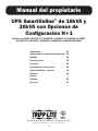
Manual del propietario
UPS SmartOnline
®
de 16kVA y
20kVA con Opciones de
Configuración N+1
Modelos: SU16KRT, SU16KRT-1TF, SU16KRT8, SU16KRTG, SU16KRTHW, SU20KRT,
SU20KRT-1TF, SU20KRT8, SU20KRTG, SU20KRTHW, SU20KRTHWTFASSM
Introducción 14
Advertencias de seguridad importantes 15
Montaje 16
Características 18
Conexión 20
Operación de rodeo manual 22
Almacenamiento y servicio 24
Garantía 24
English 1
Français 25
Русский 37
1111 W. 35th Street, Chicago, IL 60609 USA • www.tripplite.com/support
Copyright © 2018 Tripp Lite. Todos los derechos reservados.

14
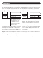
Introducción
Su sistema UPS de 16kVA o 20kVA de Tripp Lite incluye dos módulos de potencia de 8Kva o 10kVA, junto con un PDU en paralelo y un
cable de comunicaciones que combina la salida de los dos módulos de potencia del UPS para alimentar directamente su equipo. Su UPS
soporta automáticamente tolerancia a fallas N+1 a niveles de carga hasta un 50% y operación no redundante a cargas superiores al 50%.
El PDU en paralelo incluido con switch de derivación permite también el reemplazo Hot-Swap de uno o ambos módulos de potencia sin
tiempo muerto. Para asistencia adicional de la configuración, póngase en contacto con Tripp Lite.
Configuración redundante de 10 kVA
(10 kVA de carga máxima)
Configuración sin redundancia de 20 kVA
(20 kVA de carga máxima)
Cuando dos sistemas UPS tienen
una carga máxima del 50%,
su configuración recibirá una
redundancia completa y una
tolerancia a fallos con soporte
completo para la reposición del UPS
de sustitución en caliente en caso de
fallo repentino del UPS.
Cuando dos sistemas UPS tienen la carga máxima del 100%,
su configuración recibirá la capacidad completa de ambos
sistemas UPS combinados para suministrar potencia a las cargas
mayores. Esta configuración NO tiene opciones de redundancia
o tolerancia a fallas. Es posible el reemplazo Hot-Swap del
UPS en funcionamiento (Hot swap) si coloca el PDU en modo
de derivación (Consulte la Sección de “Operación Manual de
Derivación”).
Para garantizar la tolerancia a fallos, cargue los dos sistemas
UPS paralelos con un máximo del 50% de la potencia de servicio
combinada para ambos sistemas UPS. Por ejemplo, si tiene dos
sistemas UPS de 10 kVA, contará con un funcionamiento tolerante
a fallos si el nivel de carga se mantiene en 10 kVA o menos.
Puede utilizar esta configuración para ampliar la capacidad de
potencia de su UPS a 16 kVA (cuando se utilizan dos sistemas
UPS de 8 kVA) o a 20 kVA (cuando se utilizan dos sistemas UPS
de 10 kVA). En esta configuración NO está disponible la opción de
tolerancia a fallos.
Para Configuraciones de UPS de 16kVA o 20KVA
• No es compatible con operación en modo económico
• Para mejores resultados, conecte un número igual de paquetes de baterías externas a cada módulo de potencia del UPS.
Nota: Utilice el manual del módulo de potencia de 8kVA o 10kVA incluido para consultar las opciones de operación y la configuración del UPS una vez que
haya terminado la instalación de su UPS de 16kVA o 20kVA de acuerdo a la información de instalación en las páginas siguientes.
UPS de 10 kVA
Cargas de 10 kVA e inferiores
PDU
paralela
UPS de 10 kVA
UPS de 10 kVA
Cargas de 10 kVA
PDU
paralela
UPS de 10 kVA
Funcionamiento redundante Sí
Tolerancia a fallos Sí
Reposición del UPS de sustitución en
caliente
Sí
Capacidad aumentada No
Funcionamiento redundante No
Tolerancia a fallos No
Reposición del UPS de sustitución en
caliente
Sí
Capacidad aumentada Sí

15
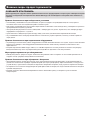
Advertencias de seguridad importantes
Advertencias sobre la ubicación
• Instale el PDU en interiores, lejos del exceso de humedad o calor, la luz solar directa, el polvo o los contaminantes conductores.
• Instale el PDU en una zona estructuralmente segura. El PDU es muy pesado, por lo que debe tener cuidado al moverlo o levantarlo.
• Haga funcionar el PDU únicamente a temperaturas de interior de entre 0 y 40 °C. Para obtener los mejores resultados, mantenga una
temperatura de interior de entre 17 y 29 ºC.
• Deje suficiente espacio alrededor de todo el UPS para que pueda ventilarse de forma adecuada.
• No instale el PDU cerca de medios de almacenamiento magnéticos, ya que esto podría dañar los datos.
Advertencias sobre la conexión de equipos
• El uso de este equipo en aplicaciones de soporte de vida en donde la falla de este equipo pueda razonablemente hacer suponer que
causará fallas en el equipo de soporte de vida o afecte significativamente su seguridad o efectividad, no está recomendado.
• Cuando la conecta a un UPS, el UPS está conectado a una fuente de energía de CD (batería). Las terminales de salida pueden tener
corriente aún cuando el sistema de UPS no esté conectado a una fuente de CA.
Advertencias de mantenimiento
• Su PDU no requiere rutina de mantenimiento. No la abra bajo ninguna circunstancia. No tiene partes internas que el usuario pueda
reparar.
Advertencias sobre la batería
• El servicio y la reparación sólo deben llevarse a cabo por personal cualificado. Durante cualquier trabajo por parte del servicio técnico,
el UPS debe apagarse o derivarse de forma manual mediante el transformador. Tenga en cuenta que esta unidad contiene voltajes que
podrían causar la muerte mientras se encuentra conectada la alimentación a la batería.
• No conecte ni desconecte los módulos de batería mientras ésta sea la fuente de alimentación del UPS, o cuando la PDU desmontable no
esté en modo derivación.
• Durante la sustitución de un módulo de batería “en caliente”, el UPS no puede proporcionar una batería de reserva en caso de producirse
un fallo en el servicio eléctrico.
GUARDE ESTAS INSTRUCCIONES.
Este manual contiene instrucciones y advertencias importantes que deben seguirse durante la instalación y mantenimiento de
todas las PDU paralelas de Tripp Lite. La falta de observar estas advertencias podría afectar su garantía.

16
2
1
Montaje
Módulo de potencia del
UPS 1
Módulo de potencia de la
batería 1
Módulo de potencia del
UPS 2
Módulo de potencia de la
batería 2
D
F
E
G
C
C
B
A
B
A
3
3
4
5
C
C
B
Nota: Se recomienda que las siguientes instrucciones de montaje se usen únicamente para los racks estándar y los racks de bastidor abierto de 4 puestos.
1
Es importante tener en cuenta que, para acomodar aplicaciones
paralelas, el equipo tiene que montarse en el siguiente orden
(consulte el diagrama): Módulo de potencia del UPS 1, módulo
de potencia del UPS 2, módulo de baterías 1 y módulo de
baterías 2.
Nota: El módulo de potencia y el módulo de baterías tienen que
instalarse en distintos estantes.
2
Las espigas de plástico incluidas
A
sostienen temporalmente
los anaqueles vacíos de montaje en bastidor
B
mientras instala
las piezas de montaje permanentes. Introduzca una espiga
cerca del centro de las abrazaderas delantera y trasera de cada
anaquel, tal como se muestra (las abrazaderas delanteras tienen
6 orificios y las traseras 3). Las espigas se fijarán en su posición.
Después de instalar las espigas, extienda los anaqueles hasta
adecuarlos a la profundidad de los rieles del bastidor. Las espigas
encajarán a través de los orificios cuadrados de los rieles del
bastidor para sostener los anaqueles. Consulte las etiquetas
del bastidor para confirmar que los anaqueles se encuentran
nivelados en todas las direcciones.
Nota: Los bordes de apoyo de los anaqueles deben mirar hacia dentro.
3
Fije los anaqueles
B
de forma permanente a los rieles utilizando
los tornillos y las arandelas acopadas
C
incluidos, tal como se
muestra.
• Para el montaje de equipos en 2U, coloque 4 tornillos en total
en la parte delantera y 4 en total en la trasera.
• Para el montaje de equipos en 3U, coloque 6 tornillos en total
en la parte delantera y 4 en total en la trasera.
Apriete todos los tornillos antes de continuar.
Advertencia: No intente instalar el equipo hasta que haya
introducido y apretado los tornil los necesarios. Las espigas
de plástico no están preparadas para soportar el peso del
equipo.
4
Fije las orejas de montaje
D
a los orificios de montaje
delanteros del equipo
E
utilizando los tornillos suministrados
F
.
Las orejas deben mirar hacia delante.
5
Con la ayuda de otra persona, levante el equipo y deslícelo en
los anaqueles de montaje. Fije el equipo al bastidor pasando
los tornillos, las tuercas y las arandelas (suministrados por el
usuario)
G
través de las orejas de montaje y dentro de los rieles
del bastidor.

17
6
10
11
8
7
9
Montaje
6
Una los 4 soportes guía de ubicación a los módulos de
potencia (2 por módulo) usando los tornillos incluidos.
7
Instale el distribuidor de cableado utilizando los tornillos
incluidos.
8
Retire las cubiertas de las terminales desenroscando los 2
tornillos y dejando expuestos los contactos del PDU. Guárdelas
para su uso a futuro.
9
Conecte el Módulo de Batería 2 al Módulo de Potencia 2 antes
de instalar el PDU.
10
Con los 4 pasadores de montaje como guía, deslice la PDU en
los soportes guías de ubicación en los módulos de potencia.
Cuando está alineada apropiadamente, los pasadores guía en
la parte posterior de la PDU tienen que encajar en los orificios
de paso que se encuentran en los módulos de potencia y se
puede realizar una conexión fija.
11
Conecte el Módulo de Batería 1 al Módulo de Potencia 1.
Acople el PDU a los módulos de potencia apretando los 4
tornillos.

18
1
1
6
5
4
4
4
7 7
22
5 5
8 88 8
3 3
3
11
12
10
12
13
13
4
7
2
5
9
9
3
1
2
1
14
14
14
14
14
Características
SUPDMB20K
(Incluido con SU16KRT, SU16KRT-1TF,
SU20KRT y SU20KRT-1TF)
SUPDMB20KHW
(Incluido con SU16KRTHW y
SU20KRTHW)
SUPDMB20KIEC
(Incluido con SU16KRTG y SU20KRTG)
Panel posterior
(todos los modelos)
SUPDMB20K8
(Incluido con SU16KRT8 y SU20KRT8)

19
Características
1
Tomacorrientes de salida L6-30R: Acepta conexión directa de los enchufes L6-30P de los equipos.
2
Interruptor de salida (30 amp): Un interruptor automático de dos polos proporciona rodeo para el sistema paralelo hacia la carga.
3
Conectores de cable paralelo: Para la comunicación en paralelo del UPS.
4
Conmutador de mantenimiento (100 amp): Controla el mantenimiento al módulo de potencia.
5
Bloque de terminales de entrada de la red pública: Use este terminal para conectar el módulo de potencia a la energía de la red
pública o al módulo transformador. Para acceder al bloque, desatornille y retire la tapa por encima.
6
Bloque de terminales de salida del equipo (SUPDMB20KHW únicamente): Use este terminal para conectar el módulo de potencia
al equipo o al módulo transformador. Para acceder al bloque, desatornille y retire la tapa por encima.
7
Interruptor de salida (20 amp): Un interruptor automático de dos polos proporciona rodeo para el sistema paralelo hacia la carga.
8
Receptáculos de salida IEC-320-C19: Acepta conexión directa de los enchufes IEC-320-C19 de los equipos.
9
Receptáculos de salida L6-20R: Aceptan conexión directa de las clavijas de seguridad L6-20P de los equipos.
10
Tapa de acceso para conectar la PDU: Retírela para realizar conexiones entre la PDU y los módulos de potencia.
11
Bloque de terminales de entrada de la PDU: Use estos terminales para conectar la PDU al módulo de potencia.
12
Pasadores guía de la PDU: Se encuentra en el costado de la PDU, ayudan a ubicar la PDU durante la instalación. Se usa junto con
los soportes guía de ubicación de la PDU (para obtener más detalles, consulte la sección “Montaje”).
13
Puestos guía de la PDU: Se encuentran en el panel trasero de la PDU, ayudan a ubicar la PDU durante la instalación. Para obtener
más detalles, consulte la sección “Montaje”.
14
Distribuidor de Cableado: Debe instalarse antes de instalar el PDU. Para más detalles, consulte la sección de Instalación.

20
1
2
N(L2)
TIERRA
L(L1)
Conexión
Conexiones de las terminales de cableado
SUPDMB20K, SUPDMB20KIEC y SUPDMB20K8
1
Desatornille los 2 tornillos para retirar las cubiertas de acceso
a la terminal de entrada.
2
Conecte los cables N (L2), tierra y entrada L (L1) de acuerdo
con las marcas en los conectores, tal como se ve en el
diagrama.
3
Después de conectar los cables de entrada, vuelva a colocas
las tapas de acceso a la terminal de entrada.
Precauciones al realizar una instalación eléctrica permanente
• El cableado debe tenderlo un electricista calificado.
• Cuando se realicen las conexiones del cableado, cerciórese de cumplir en todo momento con las regulaciones correspondientes de su
zona (por ej. National Electrical Code (NEC), en los EE. UU.]. Asegúrese también de instalar un interruptor para desconexión que sea de
fácil acceso, de manera tal que pueda cortar la entrada de CA al UPS durante incendios y otras emergencias. Asegúrese de que todos
los cables poseen funda y que están asegurados por sujetadores de conexión. Ajuste las conexiones con un torque no inferior a 24-28
pulgadas/libra (2,7-3,2 NM).
• Cerciórese de que su equipo cuenta con la conexión a tierra apropiada.
• El uso de cables del calibre incorrecto puede dañar el equipo y causar incendios. Elija el cableado y los circuitos de protección apropiados
para realizar las conexiones. Los conductores a tierra tienen que ser del mismo calibre y tipo que los conductores de potencia.
• Consulte las directivas del National Electrical Code (NEC) para los requisitos de calibre de cableado y circuito de protección de salida
apropiados.
Especificaciones y Tamaño de Cableado Recomendado para Entrada y Salida*
Para Operación Redundante N+1
Modelos (Paquetes)
Voltaje de Entrada (L-L/
L-N)
Corriente Máx
Especificada de Entrada
Servicio de Entrada
OCPD**
Tamaño Típico de
Cable de Entrada
Corriente Máx
Especificada de Salida
Tamaño Típico de
Cable de Salida
SU16KRT, SU16KRT-1TF,
SU16KRTG, SU16KRTHW,
SU16KRT8
200V-240V 46A 50A 10 mm
2
(#8 AWG)
40A 10 mm
2
(#8 AWG)
SU20KRT, SU20KRT-1TF,
SU20KRTG, SU20KRTHW,
SU20KRT8
200V-240V 56A 60A 16 mm
2
(#6 AWG)
50A 10 mm
2
(#8 AWG)
Por Capacidad de Operación
Modelos (Paquetes)
Voltaje de Entrada
(L-L/L-N)
Corriente Máx
Especificada de
Entrada
Servicio de Entrada
OCPD**
Tamaño Típico de
Cable de Entrada
Corriente Máx
Especificada de
Salida
Tamaño Típico de
Cable de Salida
SU16KRT, SU16KRT-1TF,
SU16KRTG, SU16KRTHW,
SU16KRT8
200V-240V 92A 100A 35 mm
2
(#3 AWG)
80A 25 mm
2
(#4 AWG)
SU20KRT, SU20KRT-1TF,
SU20KRTG, SU20KRTHW,
SU20KRT8
200V-240V 112A 125A 50 mm
2
(#1 AWG)
100A 35 mm
2
(#3 AWG)
* Entrada – cableado eléctrico permanente; Salida – cableado eléctrico permanente o receptáculos/tomacorrientes de salida
** OCPD – Overcurrent Protective Device [Dispositivo Protector Contra Sobrecorriente]
Страница загружается ...
Страница загружается ...
Страница загружается ...
Страница загружается ...
Страница загружается ...
Страница загружается ...
Страница загружается ...
Страница загружается ...
Страница загружается ...
Страница загружается ...
Страница загружается ...
Страница загружается ...
Страница загружается ...
Страница загружается ...
Страница загружается ...
Страница загружается ...
Страница загружается ...
Страница загружается ...
Страница загружается ...
Страница загружается ...
Страница загружается ...
Страница загружается ...
Страница загружается ...
Страница загружается ...
Страница загружается ...
Страница загружается ...
Страница загружается ...
Страница загружается ...
-
 1
1
-
 2
2
-
 3
3
-
 4
4
-
 5
5
-
 6
6
-
 7
7
-
 8
8
-
 9
9
-
 10
10
-
 11
11
-
 12
12
-
 13
13
-
 14
14
-
 15
15
-
 16
16
-
 17
17
-
 18
18
-
 19
19
-
 20
20
-
 21
21
-
 22
22
-
 23
23
-
 24
24
-
 25
25
-
 26
26
-
 27
27
-
 28
28
-
 29
29
-
 30
30
-
 31
31
-
 32
32
-
 33
33
-
 34
34
-
 35
35
-
 36
36
-
 37
37
-
 38
38
-
 39
39
-
 40
40
-
 41
41
-
 42
42
-
 43
43
-
 44
44
-
 45
45
-
 46
46
-
 47
47
-
 48
48


Tripp Lite 8 and 10kVA Parallel PDUs Инструкция по применению
- Категория
- Источники бесперебойного питания (UPS)
- Тип
- Инструкция по применению
Задайте вопрос, и я найду ответ в документе
Поиск информации в документе стал проще с помощью ИИ
на других языках
Похожие модели бренда
-
Tripp Lite 8 and 10kVA Parallel PDUs Инструкция по применению
-
Tripp Lite SmartOnline Инструкция по применению
-
Tripp Lite SUPDMB20KIEC Руководство пользователя
-
Tripp Lite SmartOnline 8kVA-10kVA UPS Инструкция по применению
-
Tripp Lite OMNIVSX1000 Инструкция по применению
-
-
-
Tripp Lite SU10000RT3U Инструкция по применению
-
Tripp Lite PDUB15 Инструкция по применению
-