Yamaha YST-RSW300 Инструкция по применению
- Категория
- Усилители для музыкальных инструментов
- Тип
- Инструкция по применению

YAMAHA ELECTRONICS CORPORATION, USA
6660 ORANGETHORPE AVE., BUENA PARK, CALIF. 90620, U.S.A.
YAMAHA CANADA MUSIC LTD.
135 MILNER AVE., SCARBOROUGH, ONTARIO M1S 3R1, CANADA
YAMAHA ELECTRONIK EUROPA G.m.b.H.
SIEMENSSTR. 22-34, 25462 RELLINGEN BEI HAMBURG, GERMANY
YAMAHA ELECTRONIQUE FRANCE S.A.
RUE AMBROISE CROIZAT BP70 CROISSY-BEAUBOURG 77312 MARNE-LA-VALLEE CEDEX02, FRANCE
YAMAHA ELECTRONICS (UK) LTD.
YAMAHA HOUSE, 200 RICKMANSWORTH ROAD WATFORD, HERTS WD18 7GQ, ENGLAND
YAMAHA SCANDINAVIA A.B.
J A WETTERGRENS GATA 1, BOX 30053, 400 43 VÄSTRA FRÖLUNDA, SWEDEN
YAMAHA MUSIC AUSTRALIA PTY, LTD.
17-33 MARKET ST., SOUTH MELBOURNE, 3205 VIC., AUSTRALIA
©
2007 All rights reserved.
Printed in Indonesia WK23280
G
YST-RSW300
SUBWOOFER SYSTEM
ENCEINTE A CAISSON DE GRAVE
OWNER’S MANUAL
MODE D’EMPLOI
BEDIENUNGSANLEITUNG
BRUKSANVISNING
MANUALE DI ISTRUZIONI
MANUAL DE INSTRUCCIONES
GEBRUIKSAANWIJZING
YST-RSW300
0101YST-RSW300_cv01_en.fm Page 1 Thursday, February 1, 2007 2:31 PM

i En
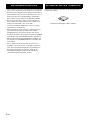
Thank you for selecting this Yamaha subwoofer system.
Please read the following operating precautions before use.
Yamaha will not be held responsible for any damage and/or injury
caused by not following the cautions below.
• To assure the finest performance, please read this manual
carefully. Keep it in a safe place for future reference.
• Install this unit in a cool, dry, clean place - away from windows,
heat sources, sources of excessive vibration, dust, moisture and
cold. Avoid sources of humming (transformers, motors). To
prevent fire or electrical shock, do not expose this unit to rain or
water.
• Never open the cabinet. If something drops into the set, contact
your dealer.
• The voltage to be used must be the same as that specified on the
rear panel. Using this unit with a higher voltage than specified
is dangerous and may cause a fire and/or electric shock.
• To reduce the risk or fire or electric shock, do not expose this
unit to rain or moisture.
• Do not use force on switches, controls or connection wires.
When moving the unit, first disconnect the power plug and the
wires connected to other equipment. Never pull the wires
themselves.
• When not planning to use this unit for a long period (ie.,
vacation, etc.), disconnect the AC power plug from the wall
outlet.
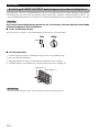
• Since this unit has a built-in power amplifier, heat will radiate
from the rear panel. Place the unit apart from the walls, allowing
at least 20 cm of space above, behind and on both sides of the
unit to prevent fire or damage. Furthermore, do not position
with the rear panel facing down on the floor or other surfaces.
• Do not cover the rear panel of this unit with a newspaper, a
tablecloth, a curtain, etc. in order not to obstruct heat radiation.
If the temperature inside the unit rises, it may cause fire,
damage to the unit and/or personal injury.
• Do not place the following objects on this unit:
- Glass, china, small metallic etc.
If glass etc. falls by vibrations and breaks, it may cause bodily
injury.
- A burning candle etc.
If the candle falls by vibrations, it may cause fire and bodily
injury.
- A vessel with water in it
If the vessel falls by vibrations and water spills, it may cause
damage to the speaker, and/or you may get an electric shock.
• Do not place this unit where foreign objects such as water drips
might fall. It might cause a fire, damage to this unit, and/or
personal injury.
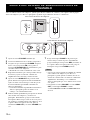
• Never put a hand or a foreign object into the YST port located
on the right side of this unit. When moving this unit, do not hold
the port as it might cause personal injury and/or damage to this
unit.
• Never place a fragile object near the YST port of this unit. If the
object falls or drops by the air pressure, it may cause damage to
the unit and/or personal injury.
• Never open the cabinet. It might cause an electric shock since
this unit uses a high voltage. It might also cause personal injury
and/or damage to this unit.
• When using a humidifier, be sure to avoid condensation inside
this unit by allowing enough spaces around this unit or avoiding
excess humidification. Condensation might cause a fire,
damage to this unit, and/or electric shock.
• Super-bass frequencies reproduced by this unit may cause a
turntable to generate a howling sound. In such a case, move this
unit away from the turntable.
• This unit may be damaged if certain sounds are continuously
output at high volume level. For example, if 20 Hz-50 Hz sine
waves from a test disc, bass sounds from electronic instruments,
etc. are continuously output, or when the stylus of a turntable
touches the surface of a disc, reduce the volume level to prevent
this unit from being damaged.
• If you hear distorted noise (i.e., unnatural, intermittent
“rapping” or “hammering” sounds) coming from this unit,
reduce the volume level. Extremely loud playing of a movie
soundtrack’s low frequency, bass-heavy sounds or similarly
loud popular music passages can damage this speaker system.
• Vibration generated by super-bass frequencies may distort
images on a TV. In such a case, move this unit away from the
TV set.
• Do not attempt to clean this unit with chemical solvents as this
might damage the finish. Use a clean, dry cloth.
• Be sure to read the “TROUBLESHOOTING” section regarding
common operating errors before concluding that the unit is
faulty.
• Install this unit near the wall outlet and where the AC power
plug can be reached easily.
• Secure placement or installation is the owner’s
responsibility. Yamaha shall not be liable for any accident
caused by improper placement or installation of speakers.
CAUTION: Read this before operating your unit.
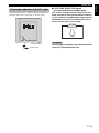
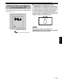
This unit features a magnetically shielded design, but
there is still a chance that placing it too close to a TV set
might impair picture color. Should this happen, move
this unit away from the TV set.
This unit is not disconnected from the AC power source
as long as it is connected to the wall outlet, even if this
unit itself is turned off. In this state, this unit is designed
to consume a very small quantity of power.

1 En
English
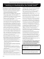
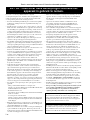
SPECIAL INSTRUCTIONS FOR U.K. MODEL
For U.K. customers
If the socket outlets in the home are not suitable for the plug supplied with this appliance, it should be cut off and an
appropriate 3 pin plug fitted. For details, refer to the instructions described below.
Note: The plug severed from the mains lead must be destroyed, as a plug with bared flexible cord is hazardous if engaged
in a live socket outlet.
FEATURES .......................................................................................................................................................................2
SUPPLIED ACCESSORIES ...........................................................................................................................................2
PLACEMENT ..................................................................................................................................................................3
CONTROLS AND THEIR FUNCTIONS .....................................................................................................................4
CONNECTIONS ..............................................................................................................................................................6
[1] Connecting to line output (pin jack) terminals of the amplifier ..............................................................................6
[2] Connecting to speaker output terminals of the amplifier .........................................................................................8
Connecting to the INPUT1/OUTPUT terminals of the subwoofer .............................................................................10
Plug in the subwoofer to the AC outlet .......................................................................................................................11
ADJUSTING THE SUBWOOFER BEFORE USE ....................................................................................................12
AUTOMATIC POWER-SWITCHING FUNCTION .................................................................................................13
Changing the AUTO STANDBY setting ....................................................................................................................13
FREQUENCY CHARACTERISTICS .........................................................................................................................14
ADVANCED YAMAHA ACTIVE SERVO TECHNOLOGY II ..............................................................................15
TROUBLESHOOTING .................................................................................................................................................16
SPECIFICATIONS ........................................................................................................................................................17
IMPORTANT:
THE WIRES IN MAINS LEAD ARE COLOURED IN ACCORDANCE WITH THE FOLLOWING CODE:
Blue: NEUTRAL
Brown: LIVE
As the colours of the wires in the mains lead of this apparatus may not correspond with the coloured markings
identifying the terminals in your plug, proceed as follows: The wire which is coloured BLUE must be connected to
the terminal which is marked with the letter N or coloured BLACK. The wire which is coloured BROWN must be
connected to the terminal which is marked with the letter L or coloured RED. Making sure that neither core is
connected to the earth terminal of the three pin plug.
For Canadian Customers
To prevent electric shock, match wide blade of plug to wide slot and fully insert.
This Class B digital apparatus complies with Canadian ICES-003.
VOLTAGE SELECTOR
(For Asia and General models only)
The voltage selector switch on the rear panel of this unit must be set for your local main voltage BEFORE
plugging this unit into the AC main supply. Voltages are 110/120/220/230-240 V AC, 50/60 Hz.
CONTENTS

2 En
• This subwoofer system employs Advanced Yamaha
Active Servo Technology II, which Yamaha has
developed for reproducing higher quality super-bass
sound (refer to page 15 for details on Advanced Yamaha
Active Servo Technology II). This super-bass sound
adds a more realistic, theater-in-the-home effect to your
stereo system.
• This subwoofer can be easily added to your existing
audio system by connecting to either the speaker
terminals or the line output (pin jack) terminals of the
amplifier.
• For the effective use of the subwoofer, the subwoofer’s
super-bass sound should be matched to the sounds of
your main speakers. You can create the best sound
quality for various listening conditions by using the
HIGH CUT control and the PHASE switch.
• The Automatic power-switching function saves you the
trouble of pressing the STANDBY/ON button to turn the
power on and off.
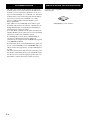
• This subwoofer system is equipped with a linear port
unique to Yamaha that provides smooth bass response
during playback, minimizing extraneous noise not
included in the original input signal.
After unpacking, check that the following parts are
contained.
Non-skid pads (1 set: 4 pieces)
FEATURES SUPPLIED ACCESSORIES

3 En
English
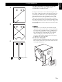
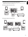
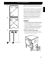
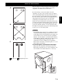
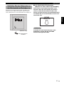
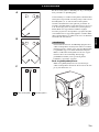
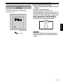
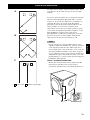
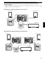
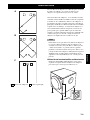
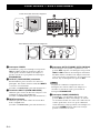
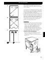
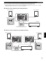
( : subwoofer : main speaker)
One subwoofer will have a good effect on your audio
system, however, the use of two subwoofers is
recommended to obtain more effect.
If using one subwoofer, it is recommended to place it on
the outside of either the right or the left main speaker (see
A). If using two subwoofers, it is recommended to place
them on the outside of each main speaker (see B). The
placement shown in C is also possible, however, if the
subwoofer system is placed directly facing the wall, the
bass effect may die because the sound from it and the sound
reflected by the wall may cancel out each other. To prevent
this from happening, face the subwoofer system at an angle
as in A or B.
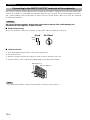
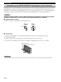
There may be a case that you cannot obtain enough
super-bass sounds from the subwoofer when listening in
the center of the room. This is because “standing waves”
have been developed between two parallel walls and
they cancel the bass sounds. In such a case, face the
subwoofer obliquely to the wall. It also may be
necessary to break up the parallel surfaces by placing
bookshelves etc. along the walls.
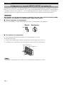
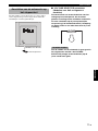
Use the non-skid pads
Put the provided non-skid pads at the four corners on the
bottom of the subwoofer to prevent the subwoofer from
moving by vibrations etc.
PLACEMENT
A
B
C
Note

4 En
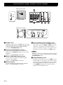
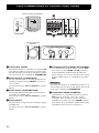
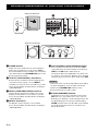
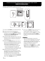
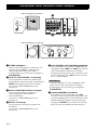
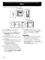
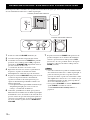
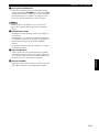
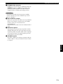
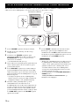
1 POWER switch
Normally, set this switch to the ON position to use the
subwoofer. In this state, you can turn on the subwoofer
or turn the subwoofer into the standby mode by
pressing the STANDBY/ON switch.
2 OUTPUT (TO SPEAKERS) terminals
Can be used for connecting to the front speakers.
Signals from the INPUT1 terminals are sent to these
terminals.
(Refer to “CONNECTIONS” for details.)
3 INPUT1 (FROM AMPLIFIER) terminals
Used to connect the subwoofer with the speaker
terminals of the amplifier.
(Refer to “CONNECTIONS” for details.)
4 INPUT2 terminals
Used to input line level signals from the amplifier.
(Refer to “CONNECTIONS” for details.)
5 AUTO STANDBY (OFF/LOW/HIGH) switch
This switch is originally set to the OFF position. By
setting this switch to the HIGH or LOW position, the
subwoofer’s automatic power-switching function
operates as described on page 13. If you do not need
this function, leave this switch in the OFF position.
Make sure to change the setting of this switch only when
the subwoofer is set in the standby mode by pressing the
STANDBY/ON switch.
6
PHASE (NORM/REV) switch
Normally, this switch is to be set to the REV (reverse)
position. However, according to your speaker systems
or the listening condition, there may be a case when
better sound quality is obtained by setting this switch
to the NORM (normal) position. Select the better
position by monitoring the sound.
CONTROLS AND THEIR FUNCTIONS
40Hz
140Hz
010
STANDBY/ON HIGH CUT
VOLUME
SUBWOOFER SYSTEM YST-RSW300
OUTPUT
TO SPEAKERS
INPUT
2
/MONO
LOW
AUTO
STANDBY
INPUT 1
FROM AMPLIFIER
POWER
ON
OFF
OFF
HIGH
NORM
REV
PHASE
8
7
90
HIGH
OFF
LOW
NORM
REV
1
65
4
OUTPUT
TO SPEAKERS
/MONO
INPUT
2
AUTO
STANDBY
PHASE
FROM AMPLIFIER
INPUT 1
2
3
R
L
L
L
R
R
Subwoofer rear panel
Subwoofer front panel
(U.S.A. model)
Note

5 En
CONTROLS AND THEIR FUNCTIONS
English
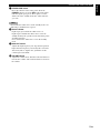
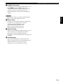
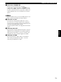
7
STANDBY/ON switch
Press this switch to turn on the power when the
POWER switch is set in the ON position (the status
indicator lights up in green). Press again to set the
subwoofer in the standby mode (the status indicator
goes off).
Even while the subwoofer is in the standby mode, it is
still using a small amount of power.
8
Status indicator
Lights up in green while the subwoofer is on.
Lights up in red while the subwoofer is set in the
standby mode by the operation of the automatic power-
switching function.
Goes off when the subwoofer is set in the standby
mode.
9
HIGH CUT control
Adjusts the high frequency cut off point. Frequencies
higher than the frequency selected by this control are
all cut off (and no output). One graduation of this
control represents 10 Hz.
0
VOLUME control
Adjusts the volume level. Turn the control clockwise to
increase the volume, and counterclockwise to decrease
the volume.
Note

6 En
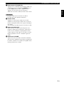
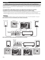
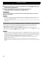
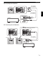
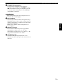
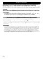
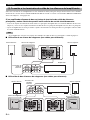
Choose one of the following two connecting methods that is more suitable for your audio system.
■ Choose [1] (pages 6-7) if your amplifier has line output (pin jack) terminal(s)
■ Choose [2] (pages 8-9) if your amplifier has no line output (pin jack) terminal
Unplug the subwoofer and other audio/video components before making connections.
• All connections must be correct, that is to say L (left) to L, R (right) to R, “+” to “+” and “–” to “–”. Also, refer to
the owner’s manual of your component to be connected to the subwoofer.
• After all connections are completed, plug in the subwoofer and other audio/video components.
• To connect with a Yamaha DSP amplifier (or AV receiver), connect the SUBWOOFER (or LOW PASS etc.) terminal
on the rear of the DSP amplifier (or AV receiver) to the /MONO INPUT2 terminal of the subwoofer.
• When connecting the subwoofer to the SPLIT SUBWOOFER terminals on the rear of the DSP amplifier, be sure to
connect the /MONO INPUT2 terminal to the “L” side and the INPUT2 terminal to the “R” side of the SPLIT
SUBWOOFER terminals.
• Some amplifiers have line output terminals labeled PRE OUT. When you connect the subwoofer to the PRE OUT
terminals of the amplifier, make sure that the amplifier has at least two sets of PRE OUT terminals. If the amplifier
has only one set of PRE OUT terminals, do not connect the subwoofer to the PRE OUT terminals. Instead, connect
the subwoofer to the speaker output terminals of the amplifier (refer to pages 8-9).
• When connecting to a monaural line output terminal of the amplifier, connect the /MONO INPUT2 terminal.
• When connecting to line output terminals of the amplifier, other speakers should not be connected to the OUTPUT
terminals on the rear panel of the subwoofer. If connected, they will not produce sound.
CONNECTIONS
Caution
Notes
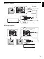
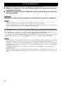
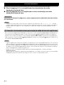
[1] Connecting to line output (pin jack) terminals of the amplifier
L
L R
Notes
L

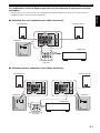
7 En
CONNECTIONS
English
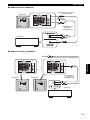
■ Using one subwoofer
■ Using two subwoofers
OUTPUT
TO SPEAKERS
INPUT
2
/MONO
LOW
AUTO
STANDBY
INPUT 1
FROM AMPLIFIER
POWER
ON
OFF
OFF
HIGH
NORM
REV
PHASE
OUTPUT
TO SPEAKERS
INPUT
2
/MONO
FROM AMPLIFIER
INPUT 1
R
L
L
L
R
R
Subwoofer
Amplifier
Mono pin cable
(not included)
Audio pin cable
(not included)
OUTPUT
TO SPEAKERS
INPUT
2
/MONO
LOW
AUTO
STANDBY
INPUT 1
FROM AMPLIFIER
POWER
ON
OFF
OFF
HIGH
NORM
REV
PHASE
OUTPUT
TO SPEAKERS
INPUT
2
/MONO
OUTPUT
TO SPEAKERS
INPUT
2
/MONO
FROM AMPLIFIER
INPUT 1
FROM AMPLIFIER
INPUT 1
OUTPUT
TO SPEAKERS
INPUT
2
/MONO
LOW
AUTO
STANDBY
INPUT 1
FROM AMPLIFIER
POWER
ON
OFF
OFF
HIGH
NORM
REV
PHASE
R
L
L
L
R
R
R
L
L
L
R
R
Amplifier
Mono pin cable (not included)
Mono pin cable
(not included)
Subwoofer Subwoofer

8 En
CONNECTIONS
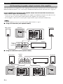
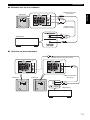
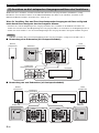
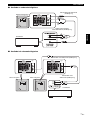
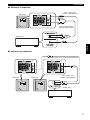
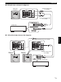
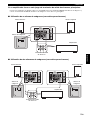
Select this method if your amplifier has no line output (pin jack) terminal. For details about the connection method of the
INPUT1/OUTPUT terminals, see the “Connecting to the INPUT1/OUTPUT terminals of the subwoofer” on page 10.
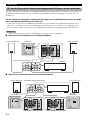
If your amplifier has two sets of main speaker output terminals and both terminals can
output sound signals simultaneously:
• Connect one set of main speaker output terminals of the amplifier to the INPUT1 terminals of the subwoofer, and
connect the other set of main speaker output terminals of the amplifier to the main speakers.
• Set the amplifier so that both sets of main speaker output terminals output sound signals simultaneously.
If your amplifier has only one set of main speaker output terminals, see page 9.
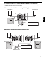
■ Using one subwoofer (with speaker cables)
■ Using two subwoofers (with speaker cables)
[2] Connecting to speaker output terminals of the amplifier
Note
OUTPUT
TO SPEAKERS
INPUT
2
/MONO
LOW
AUTO
STANDBY
INPUT 1
FROM AMPLIFIER
POWER
ON
OFF
OFF
HIGH
NORM
REV
PHASE
OUTPUT
TO SPEAKERS
/MONO
INPUT
2
FROM AMPLIFIER
INPUT 1
R
L
L
L
R
R
Right speaker
Subwoofer Left speaker
Amplifier
Speaker
output
terminals
OUTPUT
TO SPEAKERS
INPUT
2
/MONO
LOW
AUTO
STANDBY
INPUT 1
FROM AMPLIFIER
POWER
ON
OFF
OFF
HIGH
NORM
REV
PHASE
OUTPUT
TO SPEAKERS
INPUT
2
/MONO
LOW
AUTO
STANDBY
INPUT 1
FROM AMPLIFIER
POWER
ON
OFF
OFF
HIGH
NORM
REV
PHASE
OUTPUT
TO SPEAKERS
/MONO
INPUT
2
OUTPUT
TO SPEAKERS
/MONO
INPUT 1
FROM AMPLIFIER
INPUT
2
FROM AMPLIFIER
INPUT 1
R
L
L
L
R
R
R
L
L
L
R
R
Amplifier
Right speaker
Left speaker
Subwoofer
Subwoofer
Speaker
output
terminals

9 En
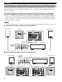
CONNECTIONS
English
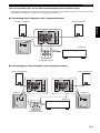
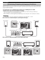
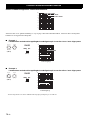
If your amplifier has only one set of main speaker output terminals:
Connect the speaker output terminals of the amplifier to the INPUT1 terminals of the subwoofer, and connect the
OUTPUT terminals of the subwoofer to the main speakers.
■ Using one subwoofer (with speaker cables)
■ Using two subwoofers (with speaker cables)
OUTPUT
TO SPEAKERS
INPUT
2
/MONO
LOW
AUTO
STANDBY
INPUT 1
FROM AMPLIFIER
POWER
ON
OFF
OFF
HIGH
NORM
REV
PHASE
OUTPUT
TO SPEAKERS
/MONO
INPUT
2
FROM AMPLIFIER
INPUT 1
R
L
L
L
R
R
Right speaker
Left speaker
Subwoofer
Amplifier
Speaker output
terminals
OUTPUT
TO SPEAKERS
INPUT
2
/MONO
LOW
AUTO
STANDBY
INPUT 1
FROM AMPLIFIER
POWER
ON
OFF
OFF
HIGH
NORM
REV
PHASE
OUTPUT
TO SPEAKERS
INPUT
2
/MONO
LOW
AUTO
STANDBY
INPUT 1
FROM AMPLIFIER
POWER
ON
OFF
OFF
HIGH
NORM
REV
PHASE
OUTPUT
TO SPEAKERS
/MONO
INPUT
2
FROM AMPLIFIER
INPUT 1
OUTPUT
TO SPEAKERS
/MONO
INPUT
2
FROM AMPLIFIER
INPUT 1
R
L
L
L
R
R
R
L
L
L
R
R
Right speaker Left speaker
Subwoofer
Speaker output
terminals
Amplifier
Subwoofer

10 En
CONNECTIONS
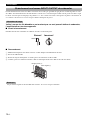
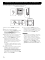
For connection, keep the speaker cables as short as possible. Do not bundle or roll up the excess part of the cables. If the
connections are faulty, no sound will be heard from the subwoofer or the speakers, or both of them. Make sure that the +
and – polarity markings of the speaker cables are observed and set correctly. If these cables are reversed, the sound will
be unnatural and lack bass.
Do not let the bare speaker wires touch each other, because this could damage the
subwoofer or the amplifier, or both of them.
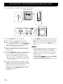
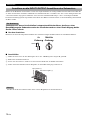
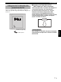
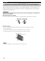
■ Before connecting
Remove the insulation coating at the extremity of each speaker cable by twisting the coating off.
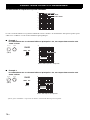
■ How to connect
1 Press and hold the terminal’s tab, as shown in the figure below.
2 Insert the bare wire.
3 Release your finger from the tab to allow it to lock securely on the cable’s wire end.
4 Test the firmness of the connection by pulling lightly on the cable at the terminal.
Do not insert the insulation coating into the hole. The sound may not be produced.
Connecting to the INPUT1/OUTPUT terminals of the subwoofer
Caution
Good No Good
10mm
(3/8”)
2
1
Black: negative (–)
Red: positive (+)
Note

11 En
CONNECTIONS
English
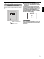
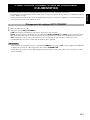
After all connections are completed, plug in the subwoofer
and other audio/video components to the AC outlet.
■ VOLTAGE SELECTOR switch
(For Asia and General models only)
This unit has a voltage selector switch on the rear
panel. If the preset setting of the switch is incorrect,
set the switch to the proper voltage range (110/120/
220/230-240 V) of your area. Consult your dealer if
you are unsure of the correct setting.
Do not plug the subwoofer to the AC outlet before
setting the VOLTAGE SELECTOR.
Plug in the subwoofer to the AC outlet
OUTPUT
TO SPEAKERS
INPUT
2
/MONO
LOW
AUTO
STANDBY
INPUT 1
FROM AMPLIFIER
POWER
ON
OFF
OFF
HIGH
NORM
REV
PHASE
To AC outlet
(U.S.A. model)
WARNING
VOLTAGE
SELECTOR

12 En
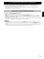
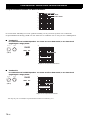
Before using the subwoofer, adjust the subwoofer to obtain the optimum volume and tone balance between the subwoofer
and the main speakers by following the procedures described below.
1 Set the VOLUME control to minimum (0).
2 Turn on the power of all the other components.
3 Make sure that the POWER switch on the rear panel is
set to the ON position, then press the STANDBY/ON
switch on the front panel to turn on the subwoofer.
* The status indicator lights up in green.
4 Play a source containing low-frequency signals and
adjust the amplifier’s volume control to the desired
listening level.
5 Adjust the HIGH CUT control to the position where
the desired response can be obtained. Normally, set the
control to the level a little higher than the main
speaker’s rated minimum reproducible frequency*.
* The main speaker’s rated minimum reproducible
frequency can be looked up in the speakers’ catalog
or owner’s manual.
6 Increase the volume gradually to adjust the volume
balance between the subwoofer and the main speakers.
Normally, set the control to the level where you can
obtain a little more bass effect than when the
subwoofer is not used. If the desired response cannot
be obtained, adjust the HIGH CUT control and the
VOLUME control again.
7 Set the PHASE switch to the position which gives you
the better bass sound. Normally, set the switch to the
REV (reverse) position. If the desired response cannot
be obtained, set the switch to the NORM (normal)
position.
• Once the volume balance between the subwoofer and
the main speakers is adjusted, you can adjust the
volume of your whole sound system by using the
amplifier’s volume control. However, if you change
the main speakers to others, you must make this
adjustment again.
• For adjusting the VOLUME control, the HIGH CUT
control and the PHASE switch, refer to
“FREQUENCY CHARACTERISTICS” on page 14.
ADJUSTING THE SUBWOOFER BEFORE USE
40Hz
140Hz
010
STANDBY/ON HIGH CUT
VOLUME
SUBWOOFER SYSTEM YST-RSW300
OUTPUT
TO SPEAKERS
INPUT
2
/MONO
LOW
AUTO
STANDBY
INPUT 1
FROM AMPLIFIER
POWER
ON
OFF
OFF
HIGH
NORM
REV
PHASE
NORM
REV
PHASE
3 5,6 1,6
3
7
Subwoofer rear panel
Subwoofer front panel
(U.S.A. model)
Notes

13 En
English
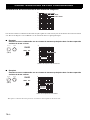
This function automatically switches the unit between standby and power-on modes.
- The subwoofer automatically places itself in standby mode if it does not receive an input signal for 7 or 8 minutes (the
status indicator lights red).
- When the subwoofer detects a bass signal input of below 200 Hz, it automatically places itself in power-on mode (the
status indicator lights green).
1 Set the subwoofer to standby.
2 Change the AUTO STANDBY setting.
- LOW: Normally select this position to activate this function.
- HIGH: If this function does not operate with AUTO STANDBY switch set to LOW, select this position so that the
subwoofer detects input signals with a lower level and switches the power on automatically.
- OFF: Select this position to deactivate this function, for example, when the subwoofer switches the power on
unexpectedly by sensing noises from other appliances.
• This function does not operate when the POWER switch is set to the OFF position, or when you manually set the
subwoofer to the standby mode by pressing the STANDBY/ON switch.
• Noise received from other appliances may extend the time period before the subwoofer places itself in the standby
mode to more than 8 minutes.
AUTOMATIC POWER-SWITCHING FUNCTION
Changing the AUTO STANDBY setting
Notes

14 En
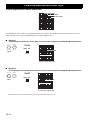
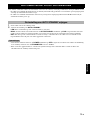
This subwoofer’s frequency characteristics
The figures below show the optimum adjustment of each control and the frequency characteristics when this subwoofer
is combined with a typical main speaker system.
■ Example 1
When combined with a 4” or 5” (10 cm or 13 cm) acoustic suspension, 2 way system main
speakers:
■ Example 2
When combined with an 8” or 10” (20 cm or 25 cm) acoustic suspension, 2 way system main
speakers:
*This diagram does not depict actual frequency response characteristics accurately.
FREQUENCY CHARACTERISTICS
(70Hz)
(REV)
(50Hz)
(REV)
20 50 100 200 500Hz
40
50
60
70
80
90
dB
HIGH CUT 40 Hz
HIGH CUT 90 Hz
HIGH CUT 140 Hz
40Hz
140Hz
010
HIGH CUT
VOLUME
PHASE
REVNORM
20 50 100 200 500Hz
40
50
60
70
80
90
dB
YST-RSW300
Main
speaker
Frequency response graph*
40Hz
140Hz
010
HIGH CUT
VOLUME
PHASE
REVNORM
20 50 100 200 500Hz
40
50
60
70
80
90
dB
YST-RSW300
Main
speaker
Frequency response graph*

15 En
English
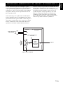
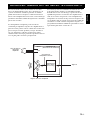
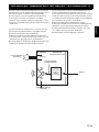
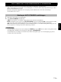
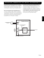
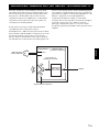
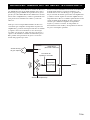
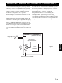
In 1988, Yamaha brought to the marketplace speaker
systems utilizing YST (Yamaha Active Servo Technology)
to give powerful, high quality bass reproduction. This
technique uses a direct connection between the amplifier
and speaker, allowing accurate signal transmission and
precise speaker control.
As this technology uses speaker units controlled by the
negative impedance drive of the amplifier and resonance
generated between the speaker cabinet volume and port, it
creates more resonant energy ( the “air woofer” concept)
than the standard bass reflex method. This allows bass
reproduction from much smaller cabinets than before.
Yamaha’s newly developed Advanced YST II adds many
refinements to Yamaha Active Servo Technology,
allowing better control of the forces driving the amplifier
and speaker. From the amplifier’s point of view, the
speaker impedance changes depending on the sound
frequency. Yamaha developed a new circuit design
combining negative-impedance and constant-current
drives, which provides a more stable performance and
clear bass reproduction without any murkiness.
ADVANCED YAMAHA ACTIVE SERVO TECHNOLOGY II
High-amplitude
bass sound
Port
Cabinet
Advanced impedance
Converter
Active
Servo
Processing
Amplifier
Signals of low amplitude
Air woofer (Helmholtz
resonator)
Signals

16 En
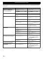
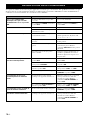
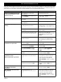
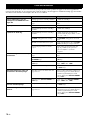
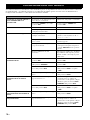
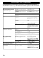
Refer to the chart below when this unit does not function properly. If the problem you are experiencing is not listed below
or if the instructions given below do not help, disconnect the power cord and contact your authorized Yamaha dealer or
service center.
TROUBLESHOOTING
Problem Cause What to Do
Power is not supplied even
though the STANDBY/ON switch
is set to the ON position.
The power plug is not securely
connected.
Connect it securely.
The POWER switch is set to the OFF
position.
Set the POWER switch to the ON
position.
No sound. The volume is set to minimum. Raise the volume up.
Speaker cables are not connected
securely.
Connect them securely.
Sound level is too low. Speaker cables are not connected
correctly.
Connect them correctly, that is L (left) to
L, R (right) to R, “+” to “+” and “–” to
“–”.
Setting of the PHASE switch is not
proper.
Set the PHASE switch to the other
position.
A source sound with few bass
frequencies is played.
Play a source sound with bass
frequencies. Set the HIGH CUT control
to a higher position.
It is influenced by standing waves. Reposition the subwoofer or break up
the parallel surface by placing
bookshelves etc. along the walls.
The subwoofer does not turn on
automatically.
The POWER switch is set to the OFF
position.
Set the POWER switch to the ON
position.
The STANDBY/ON switch is set to the
STANDBY position.
Set the STANDBY/ON switch to the
ON position.
The AUTO STANDBY switch is set to
the OFF position.
Set the AUTO STANDBY switch to the
“HIGH” or “LOW” position.
The level of input signal is too low. Set the AUTO STANDBY switch to the
“HIGH” position.
The subwoofer does not turn into
the standby mode automatically.
There is an influence of noise generated
from external appliances etc.
Move the subwoofer farther away from
such appliances and/or reposition the
connected speaker cables. Otherwise, set
the AUTO STANDBY switch to the
OFF position.
The AUTO STANDBY switch is set to
the OFF position.
Set the AUTO STANDBY switch to the
“HIGH” or “LOW” position.
The subwoofer turns into the
standby mode unexpectedly.
The level of input signal is too low. Set the AUTO STANDBY switch to the
“HIGH” position.
The subwoofer turns on
unexpectedly.
There is an influence of noise generated
from external appliances etc.
Move the subwoofer farther away from
such appliances and/or reposition the
connected speaker cables. Otherwise, set
the AUTO STANDBY switch to the
OFF position.

17 En
English
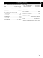
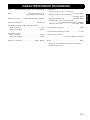
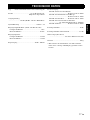
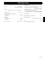
Type ......Advanced Yamaha Active Servo Technology II
Driver ........................................25 cm (10”) cone woofer
Magnetic shielding type
Output Power .............. 250 W (100 Hz, 5 Ω 10% T.H.D)
Dynamic Power ............................................. 270 W, 5 Ω
Input Sensitivity (50 Hz, 250 W/5 Ω, L+R)
Speaker terminal .................................................. 1.0 V
RCA pin jack ..................................................... 50 mV
Input Impedance
Speaker terminal ................................................ 2.2 kΩ
RCA pin jack ...................................................... 12 kΩ
Frequency Response ................................ 20 Hz - 160 Hz
Power Supply
U.S.A. and Canada models ...............AC 120V, 60 Hz
U.K. and Europe models ...................AC 230V, 50 Hz
Australia model .................................AC 240V, 50 Hz
Asia and General models
........................AC 110/120/220/230-240 V, 50/60 Hz
Korea model ......................................AC 220V, 60 Hz
Power Consumption ................................................. 80 W
Standby Power Consumption .................................0.5 W
Dimensions (W x H x D)
...................................... 372 mm x 400 mm x 428 mm
(14-5/8” x 15-3/4” x 16-7/8”)
Weight ................................................20 kg (44 lbs. 1oz.)
* Please note that all specifications are subject to change
without notice.
SPECIFICATIONS

i Fr
Nous vous remercions d’avoir porté votre choix sur ce subwoofer de Yamaha.
Tenir compte des précautions ci-dessous avant de faire
fonctionner l’appareil. Yamaha ne saurait être tenue pour
responsable de tout dommage et/ou blessure dûs à un non-respect
des mises en garde ci-dessous.
• Pour garantir les meilleures performances possibles, lire ce
manuel avec attention. Le garder dans un endroit sûr
pour une utilisation ultérieure.
• Installer cette unité dans un endroit frais, sec et propre - loin des
fenêtres, sources de chaleur et d’endroits où les vibrations, la
poussière, l’humidité ou le froid sont importants. Eviter les
sources de bourdonnements (transformateurs, moteurs). Pour
éviter les incendies ou les électrocutions, ne pas exposer cette
unité à la pluie ni à l’humidité.
• Ne jamais ouvrir le boîtier. Si quelque chose tombe dedans,
contacter immédiatement le revendeur.
• La tension à utiliser doit être la même que celle spécifiée sur le
panneau arrière. Utiliser cet appareil avec une plus haute
tension que celle spécifiée est dangereux et peut causer un
incendie et/ou causer une électrocution.
• Afin d’éviter tout risque d’incendie ou d’électrocution, ne pas
exposer cet appareil à la pluie ni à l’humidité.
•N
e pas forcer les commutateurs, les touches ou les câbles de
raccordement. Lors du déplacement de l’appareil, d’abord débrancher
la prise d’alimentation et les câbles le raccordant à d’autres appareils.
Ne jamais tirer sur les cordons.
• Lorsqu on prévoit de ne pas utiliser cet appareil pendant
longtemps (pendant les vacances, par exemple), débrancher le
cordon d’alimentation CA de la prise murale.
• Cet appareil possédant un amplificateur intégré, de la chaleur
sera irradiée par le panneau arrière. Placer l’unité assez loin des
murs, en laissant toujours un espace de 20 cm au moins au-
dessus, au-dessous et des deux côtés de l’unité afin d’éviter les
risques d’incendie et de dommages. Ne pas positionner non plus
cet appareil dos au plancher ou à une autre surface.
• Ne couvrez pas le panneau arrière de cet appareil avec un journal, une
nappe, un rideau, etc. afin de ne pas empêcher la dissipation de
chaleur. Si la température à l’intérieur de cet appareil augmente, un
incendie peut se déclarer et endommager cet appareil et/ou causer une
blessure corporelle.
• Ne jamais placer les objets suivants sur cette unité :
- Des objets verres, de la vaissille, des petits objets metalliques,
etc.
Des blessures pourraient être causées par des débris de verre,
etc. dûs aux vibrations et aux brisures.
- Une bougie allumée, etc.
Si la bougie tombe sous l’effet des vibrations, elle risque de
provoquer un incendie et des blessures corporelles
.
- Un récipient contenant de l’eau
Si le récipient tombe sous l’effet des vibrations et que de l’eau
éclabousse l’enceinte, ceci risque de l’endommager
sérieusement, et/ou de provoquer des électrocutions.
• Ne pas mettre cette unité dans les endroits où des corps
étrangers, comme des jets d’eau par exemple, pourraient tomber
dedans. Ceci pourrait causer un incendie, endommager cette
unité, et/ou des blessures corporelles.
• Ne jamais introduire la main ou un corps étranger dans le port YST
situé sur le côté droit de cette unité. Ne jamais attraper l’unité par
l’orifice du port lors des déplacements, car ceci pourrait causer des
blessures corporelles et/ou endommager l’unité.
• Ne jamais placer un objet fragile à proximité du port YST de
cette unité. Si cet objet venait à chuter en raison de la pression
de l’air, il pourrait endommager l’unité et/ou causer des
blessures corporelles.
• Ne jamais ouvrir le boîtier. Ceci pourrait entraîner des
électrocutions, car cette unité fonctionne sous haute tension.
Ceci pourrait aussi causer des blessures corporelles et/ou
endommager l’unité.
• En utilisant un humidificateur, éviter la condensation à l’intérieur
de l’appareil en libérant la place autour de l’appareil ou en évitant
l’humidification extrême. La condensation peut causer un feu,
des dommages à l’appareil et/ou une électrocution.
• Les sons de très basse fréquence produits par cet appareil
peuvent provoquer un sifflement sur le tourne-disque. Dans ce
cas, éloigner cet appareil du tourne-disque.
• Cet appareil peut être endommagé si certains sons sont
continuellement émis à un niveau sonore élevé. Par exemple, si
des ondes sinusoïdales de 20 Hz-50 Hz d’un disque d’essai, des
sons de graves d’instruments électroniques, etc. sont émis en
continu ou si la pointe de lecture d’une platine tourne-disque
touche la surface d’un disque, réduire le niveau de volume pour
éviter d’endommager cet appareil.
• Si une distorsion se fait entendre (par exemple des petits coups
secs intermittents ou un “martèlement”) sur cet appareil,
diminuer le niveau sonore. La lecture à très haut volume des
sons de basse ou des sons de basses fréquences de la bande
sonore d’un film, ou de passages de musique pop de forte
intensité, sont susceptibles d’endommager ce système
d’enceintes.
• Des vibrations générées par des fréquences supergraves
risquent de déformer les images sur un téléviseur. Dans ce cas,
éloigner cet appareil du téléviseur.
• Ne pas essayer de nettoyer cette unité avec des diluants
chimiques, ceci endommagerait le fini. Utiliser un chiffon
propre et sec.
•B
ien lire la section “RESOLUTION DES PROBLEMES”
concernant les erreurs de fonctionnement communes avant de
conclure que l’unité est défecteuse.
• Installez cet appareil à proximité de la prise secteur et à un
emplacement où la fiche du câble d’alimentation est facilement
accessible.
• Le propriétaire du système est entièrement responsable du
bon positionnement et de la bonne installation du système.
Yamaha décline toute responsabilité en cas d’accident causé
par un positionnement ou une installation inadéquats des
enceintes.
ATTENTION : Tenir compte des précautions ci-dessous
avant de faire fonctionner l’appareil.
Même si cette unité dispose d’une conception à blindage
magnétique, il y a un risque possible de création
d’interférences, visibles sur les images en couleurs si elle est
placée à côté d’un téléviseur. Dans ce cas, éloigner l’unité du
téléviseur.
Cet appareil n’est pas déconnecté du secteur tant qu’il reste
branché á la prise de courant. En pareil cas, celui-ci
consomme une faible quantité d’électricité.
Страница загружается ...
Страница загружается ...
Страница загружается ...
Страница загружается ...
Страница загружается ...
Страница загружается ...
Страница загружается ...
Страница загружается ...
Страница загружается ...
Страница загружается ...
Страница загружается ...
Страница загружается ...
Страница загружается ...
Страница загружается ...
Страница загружается ...
Страница загружается ...
Страница загружается ...
Страница загружается ...
Страница загружается ...
Страница загружается ...
Страница загружается ...
Страница загружается ...
Страница загружается ...
Страница загружается ...
Страница загружается ...
Страница загружается ...
Страница загружается ...
Страница загружается ...
Страница загружается ...
Страница загружается ...
Страница загружается ...
Страница загружается ...
Страница загружается ...
Страница загружается ...
Страница загружается ...
Страница загружается ...
Страница загружается ...
Страница загружается ...
Страница загружается ...
Страница загружается ...
Страница загружается ...
Страница загружается ...
Страница загружается ...
Страница загружается ...
Страница загружается ...
Страница загружается ...
Страница загружается ...
Страница загружается ...
Страница загружается ...
Страница загружается ...
Страница загружается ...
Страница загружается ...
Страница загружается ...
Страница загружается ...
Страница загружается ...
Страница загружается ...
Страница загружается ...
Страница загружается ...
Страница загружается ...
Страница загружается ...
Страница загружается ...
Страница загружается ...
Страница загружается ...
Страница загружается ...
Страница загружается ...
Страница загружается ...
Страница загружается ...
Страница загружается ...
Страница загружается ...
Страница загружается ...
Страница загружается ...
Страница загружается ...
Страница загружается ...
Страница загружается ...
Страница загружается ...
Страница загружается ...
Страница загружается ...
Страница загружается ...
Страница загружается ...
Страница загружается ...
Страница загружается ...
Страница загружается ...
Страница загружается ...
Страница загружается ...
Страница загружается ...
Страница загружается ...
Страница загружается ...
Страница загружается ...
Страница загружается ...
Страница загружается ...
Страница загружается ...
Страница загружается ...
Страница загружается ...
Страница загружается ...
Страница загружается ...
Страница загружается ...
Страница загружается ...
Страница загружается ...
Страница загружается ...
Страница загружается ...
Страница загружается ...
Страница загружается ...
Страница загружается ...
Страница загружается ...
Страница загружается ...
Страница загружается ...
Страница загружается ...
Страница загружается ...
-
 1
1
-
 2
2
-
 3
3
-
 4
4
-
 5
5
-
 6
6
-
 7
7
-
 8
8
-
 9
9
-
 10
10
-
 11
11
-
 12
12
-
 13
13
-
 14
14
-
 15
15
-
 16
16
-
 17
17
-
 18
18
-
 19
19
-
 20
20
-
 21
21
-
 22
22
-
 23
23
-
 24
24
-
 25
25
-
 26
26
-
 27
27
-
 28
28
-
 29
29
-
 30
30
-
 31
31
-
 32
32
-
 33
33
-
 34
34
-
 35
35
-
 36
36
-
 37
37
-
 38
38
-
 39
39
-
 40
40
-
 41
41
-
 42
42
-
 43
43
-
 44
44
-
 45
45
-
 46
46
-
 47
47
-
 48
48
-
 49
49
-
 50
50
-
 51
51
-
 52
52
-
 53
53
-
 54
54
-
 55
55
-
 56
56
-
 57
57
-
 58
58
-
 59
59
-
 60
60
-
 61
61
-
 62
62
-
 63
63
-
 64
64
-
 65
65
-
 66
66
-
 67
67
-
 68
68
-
 69
69
-
 70
70
-
 71
71
-
 72
72
-
 73
73
-
 74
74
-
 75
75
-
 76
76
-
 77
77
-
 78
78
-
 79
79
-
 80
80
-
 81
81
-
 82
82
-
 83
83
-
 84
84
-
 85
85
-
 86
86
-
 87
87
-
 88
88
-
 89
89
-
 90
90
-
 91
91
-
 92
92
-
 93
93
-
 94
94
-
 95
95
-
 96
96
-
 97
97
-
 98
98
-
 99
99
-
 100
100
-
 101
101
-
 102
102
-
 103
103
-
 104
104
-
 105
105
-
 106
106
-
 107
107
-
 108
108
-
 109
109
-
 110
110
-
 111
111
-
 112
112
-
 113
113
-
 114
114
-
 115
115
-
 116
116
-
 117
117
-
 118
118
-
 119
119
-
 120
120
-
 121
121
-
 122
122
-
 123
123
-
 124
124
-
 125
125
-
 126
126
-
 127
127
-
 128
128


Yamaha YST-RSW300 Инструкция по применению
- Категория
- Усилители для музыкальных инструментов
- Тип
- Инструкция по применению
Задайте вопрос, и я найду ответ в документе
Поиск информации в документе стал проще с помощью ИИ
на других языках
- English: Yamaha YST-RSW300 Owner's manual
- français: Yamaha YST-RSW300 Le manuel du propriétaire
- italiano: Yamaha YST-RSW300 Manuale del proprietario
- español: Yamaha YST-RSW300 El manual del propietario
- Deutsch: Yamaha YST-RSW300 Bedienungsanleitung
- Nederlands: Yamaha YST-RSW300 de handleiding
- dansk: Yamaha YST-RSW300 Brugervejledning
- svenska: Yamaha YST-RSW300 Bruksanvisning
- Türkçe: Yamaha YST-RSW300 El kitabı
- suomi: Yamaha YST-RSW300 Omistajan opas
- română: Yamaha YST-RSW300 Manualul proprietarului
Похожие модели бренда
-
Yamaha YST-SW325 Инструкция по применению
-
-
Yamaha YST-SW030 Инструкция по применению
-
Yamaha NS-SW300 Инструкция по применению
-
Yamaha NS-SW500 Инструкция по применению
-
Yamaha NS-P436 Инструкция по применению
-
Yamaha NS-SW700 Инструкция по применению
-
-
-
Yamaha YST-SW030 Инструкция по применению