Atlantic Vertigo MP 025 F 220-2E-BL Руководство пользователя

Тип
Руководство пользователя
FLAT & SQUARE
EN
UA
RU
ES
P
IT
PL
ELECTRIC WATER HEATER
Enamelled steel tank
ЕЛЕКТРИЧНІ ВОДОНАГРІВАЧІ
Емальований сталевий бак
ЭЛЕКТРИЧЕСКИЙ ВОДОНАГРЕВАТЕЛЬ
Эмалированный стальной бак
TERMO ELÉCTRICO
Cuba de acero vitri cada
AQUECEDOR ELÉTRICO DE ÁGUA
Tanque de aço esmaltado
SCALDACQUA ELETTRICO
Serbatoio in acciaio smaltato
ELEKTRYCZNY PODGRZEWACZ WODY
Emaliowany zbiornik stalowy
N° : .............................................................. ......../......../20......
U0610366
DESCRIPTION/ОПИС/ОПИСАНИЕ
1
1. DESCRIPTION/ОПИС/ОПИСАНИЕ
1.1. Flat range/Плоска модель/Плоская модель
Model
Модель
Max Power Output
Максим.
Потужність/
Максим.мощность
(W) (Bт)
Voltage
Напруга/
Напряжение
(V~) (B)
Water Connexions
Підключення води
Подсоедине-ние
воды
MP 025 F 220-2E-BL 1 000 230 1/2’ p. 3/4 p. 7 p. 8
MP 040 F220-2E-BL 1 500 230 1/2’ p. 3/4 p. 7 p. 8
MP 065 F220-2E-BL 1 500 230 1/2’ p. 3/4 p. 7 p. 8
MP 080 F220-2E-BL 1 500 230 1/2’ p. 3/4 p. 7 p. 8
1.2. Square range/Квадратна модель/Квадратная модель
Model
Модель
Max Power Output
Максим.
Потужність/
Максим.мощность
(W) (Bт)
Voltage
Напруга/
Напряжение
(V~) (B)
Water Connexions
Підключення води
Подсоедине-ние
воды
030 L Acess S3 1 500 220-240 1/2’ p. 5 p. 7 p. 8
050 L Acess S3 1 500 220-240 1/2’ p. 5 p. 7 p. 8
075 L Acess S4 1 500 220-240 3/4’ p. 6 p. 7 p. 8
100 L Acess S4 1 500 220-240 3/4’ p. 6 p. 7 p. 8
150 L Acess S4 1 500 220-240 3/4’ p. 6 p. 7 p. 8
Dielectric union Safety valve
2 hours
2 год. / 2 часа
Ø 10 mm min
3
2
1
1
2
Dielectric union
Safety valve
2 hours
2 год. / 2 часа
Ø 10 mm min
3
2
1
1
2
2
WALL MOUNTED/ВСТАНОВЛЕННЯ НА СТІНІ/УСТАНОВКА НА СТЕНЕ
2
2
2. WALL MOUNTED/ВСТАНОВЛЕННЯ НА СТІНІ/УСТАНОВКА НА СТЕНЕ
2.1. Flat range/Плоска модель/Плоская модель
2.1.1. Vertical case/Вертикальний монтаж/Вертикальный монтаж
Vertical
Вертикальний
Horizontal
Горизонтальний
3
M
M
M
1
2
È
È
È
È
a
b
1
3a
5a
4a
6a
on
50 cm min.
on
YES
;
:
NO
on on
WALL MOUNTED/ВСТАНОВЛЕННЯ НА СТІНІ/УСТАНОВКА НА СТЕНЕ
2
2.1.2. Horizontal case/Горизонтальний монтаж/Горизонтальный монтаж
3a
5a
4a
6a
on
YES
;
:
NO
on
S
on
4
WALL MOUNTED/ВСТАНОВЛЕННЯ НА СТІНІ/УСТАНОВКА НА СТЕНЕ
2
2.2. Square range, ONLY VERTICAL/Квадратна модель, ТІЛЬКИ ВЕРТИКАЛЬНИЙ МОНТАЖ/
Квадратная модель, ТОЛЬКО ВЕРТИКАЛЬНЫЙ МОНТАЖ/
2.2.1. 30L – 50 L S3, ONLY VERTICAL/ 30Л – 50Л S3, ТІЛЬКИ ВЕРТИКАЛЬНО/
30Л – 50Л S3, ТОЛЬКО ВЕРТИКАЛЬНО
5
M
M
M
1
2
1
Vertical Only
Тільки Вертикальний
Solo vertical
>= 6mm
>= 6mm
2
>=
6
m
m
>=
6
m
m
WALL MOUNTED/ВСТАНОВЛЕННЯ НА СТІНІ/УСТАНОВКА НА СТЕНЕ
2
6
2.2.2. 75L –100L - 150 L S4, ONLY VERTICAL/ 75Л –100Л – 150Л S4, ТІЛЬКИ ВЕРТИКАЛЬНО/
75Л –100Л – 150Л S4, ТОЛЬКО ВЕРТИКАЛЬНО
3
5
4
6
on
50 cm min.
on
YES
;
:
NO
on
HYDRAULICS CONNECTIONS/ПІДКЛЮЧЕННЯ ДО СИСТЕМИ ВОДОПОСТАЧАННЯ/ ПОДКЛЮЧЕНИЕ К СИСТЕМЕ
ВОДОСНАБЖЕНИЯ/CONEXIÓN HIDRÁULICA/TANQUE DE AÇO ESMALTADO/ POŁĄCZENIA HYDRAULICZNE
3
È
È
u
v
w
x
y
z
{
|
EN
1. Hot water tube
2. Safety relief valve
3. Funnel
4. Pressure reducer recommended
if pressure > 5 bar 0,5 MPa (5 bars)
5. Stop valve
6. Drain to sewage
7. Cold water pipe
8. Dielectric union
UA
1.Труба гарячої води
2. Запобіжний клапан
3-6. Дренажна трубка
4. Редуктор тиску (при тиску
більш 0,4 МПа)
5. Запірна арматура
6. Каналізаційна трубка
7. Труба холодної води
8. Діелектрична муфта
ES
1. Salida de agua caliente
2. Grupo o válvula de seguridad
3. Embudo Sifónico
4. Reductor para presión superior
a 5 bares (0,5 MPa)
5. Válvula de corte
6. Vaciado – Desagüe
7. Cnducto de agua fría
8. Manguito dieléctrico
P
1. Saída de água quente
2. Válvula de seguranca
3. Funil
4. Redutor de pressão - recomen-
dado se pressão > 0,5 MPa (5 bars)
5. Válvula de corte
6. Drenagem - esgoto
7. Entrada de água fria
8. Junta dielétrica
RU
1. Πаτρубок выхода горячей воды
2. Предохранительный клапан
3. Дренажная трубка
4. Клапан редукции давления
(Устанавливается при давлении свыше
5 бар в системе (0,5 МПа))
5. Запорный кран
6. Выход в канализацию
7. Труба подачи холодной воды
8. Диэлектрическая муфта
PL
1. Wyjście ciepłej wody
2. Zespół zaworów
bezpieczeństwa
3. L ejek-Syfon
4. Reduktor ciśnienia większego
niż bara (0,5MPa)
5. Zawór odcinający
6. Opróżnianie
7. Przewód zimnej wody
8. Zlączka dielektryczna
IT
1. Condotto acqua calda
2. Valvola di sicurezza
3. Imbuto a sifone
4. Riduttore di pressione consi-
gliato se la pressione >
0,5 MPa
(5 bars)
5. Valvola d’intercettazione
6. Scarico acque re ue
7. Condotto acqua fredda
8. Giunto dielettrico
8
2
Filling
10L/min
7
ELECTRICALS CONNECTIONS/ПІДКЛЮЧЕННЯ ДО ЕЛЕКТРОМЕРЕЖІ/
ПОДКЛЮЧЕНИЕ К ЭЛЕКТРОСЕТИ/
4
8
4.1. Flat range/Плоска модель/Плоская модель/
4.2. Square range/Квадратна модель/Квадратная модель/
Entry tank probe
Датчик вхідного баку/ Датчик входного бака
White/Білий/Белый/(Flat30)
Green/Зелений/Зелёный/ (Flat 50)
Red/Червоний/Красный/ (Flat 80)
Blue/Синій/Синий/ (Flat 100)
Exit tank probe
Датчик вихідного баку (Black color / Чорний)
Датчик виходного бака (Black color/ Чёрный)
Regulation Probe
Датчик температури
Датчик температуры
Ceramic element
Керамічний елемент
Heating element
Exit Tank (Red connections)
Нагрів. елемент вихідного баку (Червоні)
Нагрев.элемент выходного бака (Красные)
Heating element
Entry Tank (White connections)
Нагрів.елемент вхід.баку (Білі конектори)
Нагрев.єлемент вход.бака (Белые конекторы)
PCB
Плата/ Плата
HMI connector
Розєм/ Разъём/
Cold water
(Blue Ring)
Холодна вода (Синє кільце)
Холодная вода (Синее кольцо)
Hot water (Red Ring)
Гаряча вода (Червоне
кільце)
Горячая вода (Красное
кольцо)
Hot water (Red Ring)
Гаряча вода(червоне кільце
Горячая вода(красное кольцо)
Cold water (Blue Ring)
Холодна вода(синє кільце)
Холодная вода(синее кольцо)
Power cable
Силовий шнур
Силовой шнур
Power cable
Силовий шнур
Силовой шнур
Thermal cut-out
with double probe
Термозапобіжник з подвійн.
датчиком/ Термопредохранитель
с двойным датчиком/
Thermal cut-out
Термозапобіжник
Термопредохранитель
Regulation Thermostat
Термостат управління
HMI
HMI DESCRIPTION/ПУЛЬТ/ПУЛЬТ/
5
9
5.1. Flat range/Плоска модель/Плоская модель/
A. Manual setting knob/Ручне налаштування/Ручная настройка/
B. Frost free mode/Ручне налаштування/ Режим Антизамерзания/
C. Shower ready indicator/Індикатор«Душ готовий»/Индикатор «Душ готов»/
D. Maximum position of temperature/Максимальна температура/Максимальная температура/
5.1. Square range/Квадратна модель/Квадратная модель/
A. Manual setting knob/Ручне налаштування/Ручная настройка/
B. Frost free mode/Ручне налаштування/Режим Антизамерзания/
C. Heating light indicator/Індикатор нагріву/Индикатор нагрева/
D. Maximum position of temperature/Максимальна температура/Максимальная температура/
C
C
A
A
D
D
B
B
10
GENERAL WARNINGS
This device is not intended for use by persons (including children) with
physical, sensory or mental disability, or by persons lacking experience or
knowledge, unless they have received from a person in charge of their
safety adequate supervision or preliminary instructions on how to use the
device. Children should be supervised to ensure that they do not play with
the appliance.
This unit can be used by children of not less than 8 years and people with
reduced physical, sensory or mental capabilities or without experience or
knowledge if they are properly supervised or if the instructions for using
the device safely have been given and if the risks are taking into account.
Children must not play with the device. Cleaning and maintenance must
not be done by children without supervision.
CAUTION! Heavy item, handle with care:
1. Install the appliance in a room which is protected from frost. If the ap-
pliance is damaged because the safety device has been blocked, it is not
covered by guarantee.
2. Make sure that the wall on which the appliance is mounted can support
the weight of the appliance when  lled with water.
3. If the appliance is to be  tted in a room or location where the ambient
temperature is higher than 35°C, provide suf cient ventilation.
4. When installed in a bathroom, do not install the appliance in volumes
V0 and V1 (See  g. 1, p.3 or p. 5). If the water heater is to install above
living space,  t a retaining tank with drain to the sewer system. Place
the water heater in a place with easy access.
5. If PER pipes are used, the installation of a thermostatic regulator on the
output pipe of the device is strongly recommended. It will be set accor-
ding to the performance of the material used.
6. Installation of a vertical or horizontal wall mounted device: To allow
the replacement of the heating element leave a free space of 500mm
between the tube ends and the wall or  xed furniture.
7. Switch off the power before removing the cover, to avoid any risk of
injury or electric shock.
8. The installation must be equipped, upstream of the appliance, with a
bipolar cut-out device (fuse, breaker switch) respecting local regulations
(30 mA earth-leakage breaker).
9. If the supply cord is damaged, it must be replaced by a special cord or
assembly available from the manufacturer or the after sales service.
11
EN
GENERAL WARNINGS
10. Mandatory installation of a safety device in a frost-free location (or any
other new device which limits the tank pressure) to 0.7 or 0.9 MPa (7 or
9 bar) according to the nominal pressure, with a size of 1/2» in the input
of the water heater, respecting the local regulations
11. Operate regularly the discharge of safety device to prevent scaling and
check that it is not blocked.
12. Hydraulic accessories should not be located between the safety valve
and the cold-water inlet. A pressure reducer (not supplied) is required
when the water supply pressure exceeds 0,5 MPa (5 bar) and will be
tted on the main supply.
13. Connect the safety device to an unpressurised outlet pipe in a frost-free
location, with a continuous slope to evacuate water during heating up
or draining the water heater.
14. The pipes used must support 1 MPa (10 bar) and 100 ° C.
15. To drain the device: Switch off the power and the supply of cold water,
open the hot water faucets and manipulate the safety valve.
16. The products described in this manual are subject to changes at any
time to be in accordance with technology and standards. The devices
comply with Electromagnetic Directive 2014/30/UE, Low Voltage Direc-
tive 2014/35/UE, Directive 2011/65/UE for RoHS and Regulation 2013/814/
UE supplementing Directive 2009/125/EC for ecodesign.
17. Do not dispose your water heater in the garbage, but hand it to
a place assigned for this purpose (collection point) where it can be
recycled.
18. This product is intended for use at a maximum altitude of 3000m.
19. Always connect the earth conductor of the cable to the earth ground
or connect the earth conductor to the appropriate terminal identi ed
by the symbol
.
20. The instruction book of this product is available by contacting the after-
sales service.
EN
12
1. PRODUCT MOUNTING See “General Warnings” N°.1 to N°.6
For product installation, refer to drawings section 2 page 3 to page 6.
2. HYDRAULIC CONNECTION See “General Warnings” N°.10 to N°.14
For hydraulic connection, refer to drawings section 4 page 8.
- It is necessary to clean the supply piping prior to the hydraulic connection. The connection to the hot
water outlet is to be carried out with a cast iron or steel sleeve or a dielectric connector, to avoid
corrosion of the pipe (direct contact iron / copper). The use of brass  ttings is prohibited.
- Always install a new safety device on the cold water pipe of the water heater, which comply with
the standards (EN 1487 in Europe), with a pressure of 0.7 or 0.9 MPa (7 or 9 bars) according
to the nominal pressure, with diameter adapt : 1/2» or 3/4” according with the range of product.
- CAUTION: Do not use the safety valve included in this packaging in France (home country and French
overseas)
3. ELECTRICAL CONNECTION
For electrical connection, refer to drawings section 4 page 8.
- The water heater can be connected and operated only on AC 230V. Connect the heater with a rigid
cable with conductors 2,5mm². Use a standardised channeling (rigid or  exible conduit) until
the calibrated housing cover.
- Directly connect devices with a cable or plug. In France, a product with plug is strictly prohibited
and cannot be sold and installed.
- Always connect the earth conductor of the cable to the earth ground wire or connect the earth
conductor to the appropriate terminal identi ed by the symbol . This connection is compulsory for
safety reasons. The earth wire green - yellow must be longer than those of phases. The installation
must be equipped, upstream of the appliance, with a bipolar cut-out device (minimum contact
distance of 3 mm fuse, breaker switch). In the case where hydraulic connexions are in insulated
material, electrical circuits shall be protected by a differential circuit breaker 30 mA adapted to local
standards.
Thermal circuit breaker (see drawings section 4 page 8): All our products are equipped with a thermostat
with thermal circuit breaker and manual resetting which cuts off the power supply to the water heater
in case of overheating. If the safety trips:
² switch off the power before taking any further action,
² remove the cover,
² check the electrical connections,
² reset the thermal circuit breaker
If the circuit breaker keeps tripping, replace the thermostat. Never short circuit the safety cut out or
the thermostat. Connect the power supply only via the terminal.
INSTALLATION
EN
13
EN
SETUP & OPERATION
- CAUTION: NEVER SWITCH ON THE WATER HEATER WITHOUT WATER: Models with an electric heating
element will be certainly damaged.
- Fill the tank completely. Before powering up, open the hot water taps, drain the pipes in order
to empty the air.
- Check the tightness of the tubes and of the  ange seal under the plastic cover. In case of leaking
tighten moderately. Check the operating of the hydraulic components and of the safety valve.
- Turn the power on. After 45 to 60 minutes, depending of the capacity of the device, the water should
drip from the drain. This is normal and due to the expansion of water. Check connection leaks
and seal. During heating and according to the water quality, hot water tanks can make a bubbling
noise. This noise is normal and does not indicate any defect of the unit.
1. FLAT RANGE
1/ SETTING KNOB (Ref A and D): Manual selection of temperature setpoint. Position of ref. D is the
maximum position of temperature setting.
2/ FROST FREE Mode
(Ref. B): Automatic regulation at frost-free temperature (7°C), in order to reduce
the electric consumption during the periods of absence of the user.
3/ SHOWER READY (Ref. C): Monitoring indicator of hot water available. When the shower symbol
is turned on, volume of hot water is equal or higher than 1 shower need.
2. SQUARE RANGE
1/ SETTING KNOB (Ref A and D): Manual selection of temperature setpoint. Position of ref. C is the
maximum position of temperature setting.
2/ FROST FREE Mode
(Ref. B): Automatic regulation at frost-free temperature (7°C), in order to reduce
the electric consumption during the periods of absence of the user.
3/ HEATING LIGHT INDICATOR
(Ref. D):. When the heating element symbol is turned on, the water is
being heated.
EN
14
TROUBLESHOOTING
MAINTENANCE
When a malfunction occurs, the user interface of the appliance can display an error code.
1. FLAT RANGE
2. SQUARE RANGE
Nothing
CAUTION: Before removing the plastic cover, make sure the power is turned off to avoid any risk of injury
or electric shock.
1. USER MAINTENANCE
Operates once a month the discharge of the safety valve to prevent scaling deposit and verify that
the safety device is not blocked. If this is not done, damage may be caused and the guarantee invalidated.
For an installation with a booster pump; before starting up, after a long period of disuse, turn the rotor fol-
lowing the advice in the manufacturer’s instructions.
2. MAINTENANCE BY A QUALIFIED PERSON
- Scaling: Remove the scale sludge. Do not scrape or hammer the lime scale deposited on the casing,
as this may damage the lining.
-
Magnesium anode: change the magnesium anode every 2 years or when its diameter is lower than 10 mm.
- Heating element: the replacement of a sheathed heating element involves draining of the water
heater and replacement of the  ange gasket. Reassemble the heating element, reasonably tight nuts
(cross tightening), check that there is no leakage after the  rst heating-up, tighten again if necessary
-
Drain: Turn off power and cold-water supply. Open hot water taps and drain valve of the safety device.
Spare parts list: thermostat,  ange gasket, heating element, heating light indicator, magnesium anode,
connection wires, electric switch. The guarantee requires genuine manufacturer’s parts to be used.
Advice to the user
² When the water has a TH > 20°f, it is recommended that this be treated. When a softener is used, the water
hardness must remain above 15°f.
² In case of prolonged absence, especially in winter, drain your appliance following the procedure above.
Fault (LED status) Meaning
Remark
2 successive «shower» blinking, 3 sec of
pause, 2 successive shower blinking…
Error 3 :
Probe fault
Change probe
2 successive «shower» blinking, 3 sec of
pause, 4 successive shower blinking
Error 9 :
Relay or PCB fault Change PCB
EN
15
EN
SCOPE OF THE GUARANTEE
The water heater must be installed, used and maintained according to best practice and conform to the stan-
dards in force in the country in which it is installed and to the instructions contained in this document. In the
European Union this appliance is covered by the statutory guarantee accorded to consumers in accordance
with directive 1999/44/CE. This guarantee comes into force when the appliance is delivered to the consumer.
In addition to the legal guarantee, certain items are covered by an extra guarantee relating only to the free
exchange of the tank and of components accepted as defective. It does not include the cost of replacement or
carriage. Refer to the table below. This commercial guarantee does not affect your statutory rights. It applies
within the country where the product was acquired, provided it is also installed in the same country. The
dealer must be informed of any damage before the product is exchanged under guarantee and the appliance
will remain available for inspection by experts from the insurance company and the manufacturer.
Statutory guarantee 2 years
Extra commercial guarantee
on enamel tank and heating
element
+3 years
Exclusions: Wear parts: magnesium anodes. Equipment which cannot be assessed (access dif cult for repair,
maintenance or assessment). Equipment exposed to abnormal environmental conditions: frost, bad wea-
ther, water which is abnormally aggressive or outside drinking standards, electrical supply with large spikes.
Equipment installed without observing current standards in the country of installation: the absence or
incorrect  tting of safety devices, abnormal corrosion due to incorrect water  tments (iron/copper contact),
incorrect earthing, inadequate cable thickness, non-observance of the connection drawings shown in these
instructions. Equipment not maintained in accordance with these instructions. Repairs or replacement
of parts or components in the equipment not carried out or authorised by the company responsible for the
guarantee. Changing a component does not extend the life of the guarantee.
The products illustrated in these instructions may be modi ed at any time to re ect changes in manufacture
and current norms.
To claim under guarantee, contact your installer or dealer. If necessary, contact:
SPAIN and PORTUGAL: Pol.Industrial Cami Ral, Calle Molinot 59-62 – 08860 – Castelldefels (Barcelona)
Tél : 902 45 45 66 /
ITALIA : 848 800 929 (al solo costo di uno chiamata a tariffa urbana) / POLSKA : ul. Plochocińska 115 , 03-044
Warszawa tel (0800)-548-098 / OTHER COUNTRIES: +33 23 87 13 846
who will inform you of what you should do. The guarantee applies only to examine products which are
accepted as faulty by the company underwriting the guarantee. It is essential that products should be retai-
ned for inspection by them.
Type / Reference: STAMP DEALER
Serial number:
Name and address of
customer:
UA
16
ПОПЕРЕДЖЕННЯ
Водонагрівач не призначений для використання особами (включаючи
дітей) з обмеженими фізичними, сенсорними чи розумовими здібностями,
або особами без досвіду чи технічних знань, без нагляду чи попереднього
інструктажу з використання водонагрівача від особи, відповідальної за
їх безпеку. Стежте, щоб діти не гралися з водонагрівачем. Водонагрівач
можуть використовувати діти починаючи з 8 річного віку
, а також особи з
обмеженими фізичними, сенсорними або розумовими можливостями чи
особи без досвіду або технічних знань, але тільки під відповідним наглядом
чи за умови, що вони були проінструктовані з безпечного використання
водонагрівача, та усі можливі ризики їм було розяснено. Чистку та
обслуговування водонагрівача мають здійснювати фахівці авторизованого
сервісного
центру. Важлива примітка: установка водонагрівача має
відповідати діючим нормам держави, в якій встановлюється водонагрівач.
У разі, якщо ви не впевнені, що ваших знань достатньо для встанвлення
водонагрівача, ми рекомендуємо звернутися до фахівця.
УВАГА: водонагрівач має значну вагу, поводьтеся з ним обережно.
1. Встановлюйте водонагрівач у приміщенні, де виключене його
замерзання.
2.
При руйнуванні водонагрівача внаслідок надлишкового тиску, що
спричинений замерзанням, блокуванням запобіжного клапану
відкладеннями води, не встановленням оригінального запобіжного
клапану водонагрівач не підлягає гарантійному обслуговуванню.
3. Переконайтеся в тому , що стіна витримає вагу приладу, наповненого
водою.
4. Якщо водонагрівач встановлюється у приміщенні або місці, де
температура навколишнього середовища постійно вища за 35°С,
необхідно
передбачити можливість його провітрювання.
5. У ванних кімнатах не встановлюйте водонагрівач у зоні 1 або 2 (див.
рис. 1.1 стор.2). Якщо водонагрівач встановлюється над житловими
приміщеннями, необхідно передбачити водозбірну ємність зі стоком у
каналізацію.
6. Розташовуйте водонагрівач у легкодоступному місці поблизу
каналізаційних зливів для зручності роботи фахівців сервісних центрів.
7. Установка вертикальна або горизонтальна настінна
.
8. Перш ніж зняти кришку, переконайтеся, що живлення вимкнене, щоб
уникнути ризику травмування або удару струмом.
UA
17
UA
ПОПЕРЕДЖЕННЯ
9. Для злива води з водонагрівача необхідно: відключити водонагрівач
від електромережі; відкрити кран гарячої води у місці споживання;
перекрити запірну арматуру на вході у водонагрівач; встановити
флажок запобіжного клапана в горизонтальне положення.
10. Електроводонагрівач має сертифікат відповідності УКР СЕПРО
11. Не викидайте цей прилад із загальним сміттям, він має бути зданий до
спеціалізованого
пункту для переробки.
12. Прилади відповідають вимогам інструкцій з електромагнітної безпеки
2014/30/UE, інструкції щодо низької напруги 2014/35/UE, інструкції
2011/65/UE стосовно ROHS та інструкції 2013/814/UE, що доповнює
директиву 2009/125/EC стосовно конструювання з урахуванням
екологічних вимог.
13. Цей виріб призначений для використання на висоті до 3000 метрів.
14. Завжди підключайте кабель заземлення до клеми заземлення яка
позначена символом
.
15. Керівництво з експлуатації данної продукції можно отриматі у відділі
післягарантійного обслуговування.
Шановні покупці! З питань гарантійного, сервісного та
післягарантійного обслуговування на території України
звертайтеся за тел.: 0-800-500-885 – безкоштовно з усіх
телефонів.
З актуальним переліком сервісних центрів можна
ознайомитися на сайті http://www.atlanticgeyser.com.ua
UA
18
1. КРІПЛЕННЯ
Кріплення водонагрівача схематично зображено на рис. 1.2 – 1.6.
Для встановлення використовувайте шаблон для свердління отворів для настінного монтажу, що
йде у комплекті.
При встановленні водонагрівача в горизонтальному положенні, патрубок подачі холоднї
води (помічений синім кільцем) повинен бути розташований знизу, а патрубок гарячої води
(помічений красним кільцем) – зверху (рис. 1.3b).
Кріплення водонагрівача повинне забезпечити щільне прилягання кріпильного кронштейна до
вертикальної поверхні.
Відстань від кришки блока автоматики до протилежної вертикальної поверхні повинна бути
не менш ніж 500 мм, щоб забезпечити доступ до блока автоматики. Це необхідна умова
безкоштовного гарантійного обслуговування водонагрівача. Роботи з демонтажу і монтажу ТЕНа і
терморегулятора у випадках зменшення зазначених розмірів оплачуються окремо.
Увага! У випадку виходу з ладу водонагрівача внаслідок його кріплення з порушеннями
вимог цього розділу водонагрівач не підлягає гарантійному обслуговуванню.
2. 2. ПІДКЛЮЧЕННЯ ДО СИСТЕМИ ВОДОПОСТАЧАННЯ
Максимальний тиск води у стояку холодного водопостачання на вході водонагрівача має бути 0,8 МПа.
Підключення водонагрівача до трубопроводів холодного і гарячого водопостачання необхідно виконувати
пластиковими або металопластиковими трубами.
Заборонено підключати водонагрівач на гнучкі шланги у звязку з тим, що вони руйнуються від перепадів
температури, недовговічні і можуть вийти з ладу (протікати, лопнути).
Приєднувані до водонагрівача труби і зєднання повинні витримувати тиск 10 бар і температуру 100°С.
Перед підключенням необхідно ретельно прочистити труби водопостачання.
Діелектрична муфта встановлюється на патрубок гарячої води.
Підключення схематично зображено на рис. 2.:
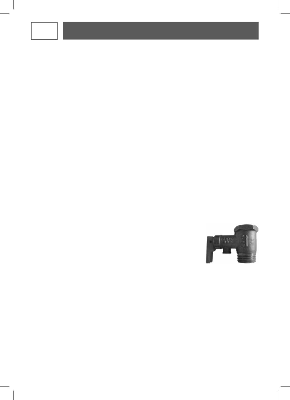
1. Встановіть на патрубок подачі холодної води водонагрівача запобіжний клапан,
що входить до комплекту поставки (рис. 5), закрутивши його не більш ніж на
3-4 оберти. Випускна трубка клапану повинна бути спрямована в постійно
спадному напрямку. Між запобіжним клапаном та патрубком холодної води
не повинно бути ніяких запірних пристроїв. Випускна (дренажна) трубка
запобіжного клапану повинна бути спрямована в постійно спадному
напрямку у навколишньому середовищі, що не замерзає. Запобіжний
клапан і дренажна трубка повинні бути захищені від морозу.
Увага! При використані клапану, що не входить до комплекту поставки, водонагрівач не підлягає
гарантійному обслуговуванню.
2. На зливний отвір запобіжного клапана встановіть дренажну трубку (у комплект постачання не входить),
для відведення води у випадку автоматичного скидання надлишкового тиску в робочому баку.
3. Виміряйте тиск у стояку холодного водопостачання, при тиску більше 0,5 МПа встановіть редуктор тиску
(у комплект постачання не входить) для зниження тиску;
4. На трубопровід холодного водопостачання встановіть фільтр грубого очищення (у комплект постачання не
входить), щоб запобігти потраплянню механічних домішок у запобіжній клапан
Запобіжний клапан конструктивно поєднує в собі зворотний і стравлюючий клапани. Зворотний клапан
виключає витікання води з бака у стояк за відсутності холодної води у водопроводі. Під час нагрівання
відбувається розширення води, що призводить до збільшення тиску в баку. При перевищені тиску води
в робочому баку понад 0,8 МПа можливе або скидання невеликої кількості води через зливний отвір
стравлюючого клапану(вода може
капати з випускної труби зменшення тиску і ця труба має залишатися
відкритою до повітря), або стравлювання надлишкового тиску крізь зворотний клапан у стояк холодного
водопостачання. Це є нормальним режимом роботи запобіжного клапану.
ВСТАНОВЛЕННЯ
Рис. 5
UA
19
UA
УСТАНОВКА
ПУСК / ФУНКЦІОНУВАННЯ
3. 3. ПІДКЛЮЧЕННЯ ДО ЕЛЕКТРОМЕРЕЖІ (рис. А)
Водонагрівач повинен живитися тільки від мережі однофазного змінного струму 230 В.
Підключення до електромережі виконується кабелем з вилкою, що йдуть у комплекті. Розетка повинна бути
заземлена. Розетка підключається до щитка електроживлення квартири, щоб не перевантажувати існуючу
проводку.
Переконайтеся, що шнур живлення водонагрівача не пошкоджений. Якщо шнур живлення пошкоджений, він
повинен бути замінений на спеціальний шнур, який є в наявності в сервісному центрі.
Електричне підключення має проводитись з використанням автоматичного вимикача з характеристиками,
відповідними до потужності водонагрівача.
У тому випадку, якщо водяні труби виготовлені з ізолюючого матеріалу, електричні ланцюги повинні бути
захищені диференціальним переривником 30 мА, відповідним до чинних норм.
Заповніть водонагрівач водою, для чого:
- переконайтесь у тому, що закрита запірна арматура на стояку гарячого водопостачання;
- відкрийте запірну арматуру на стояку холодного водопостачання;
- відкрийте кран гарячої води на змішувачі в точці споживання;
- водонагрівач буде заповнений, коли з крана гарячої води почне витікати вода;
- закрийте кран гарячої води.
Огляньте місце підключення водонагрівача до системи водопостачання и переконайтесь у відсутності
протікання води.
Увімкніть вилку в розетку та включіть автоматичний вимикач.
Увага! При першому включені приладу можлива поява запаху гару і невеликої кількості диму, що
обумовлено вигоранням поверхневого нальоту зі спіралей нагрівального елемента.
УВАГА: Ніколи не включайте водонагрівач без води.
ОПИС ПАНЕЛІ КЕРУВАННЯ (рис. 4)
ВКАЗІВКИ З ТЕХНІКИ БЕЗПЕКИ
Забороняється:
- встановлювати водонагрівач на гнучких шлангах;
- експлуатувати водонагрівач без заземлення;
- експлуатувати водонагрівач без магнієвого анода, який встановлено на фланці в середині робочого бака;
- експлуатувати водонагрівач зі знятою захисною кришкою електричного блока;
- проводити ремонтні роботи та обслуговування при увімкненому в електричну мережу водонагрівачеві;
- експлуатувати несправний водонагрівач.
1. ПЛОСКА МОДЕЛЬ
1 / РЕГУЛЯТОР ТЕМПЕРАТУРИ (REF A і D): Вибір заданого значення температури вручну. Положення
D є максимальним положенням установки температури.
2 / РЕЖИМ «FROST FREE»
(B): Автоматичне регулювання температури до температури
незамерзання (+7 °C), з метою зменшення енергоспоживання в періоди відсутності користувача.
3 / ДУШ
- умовний індикатор нагріву води. Коли всі символи світяться , означає, що нагрівся весь
обєм води у водонагрівачі.
UA
20
При несправності, на користувацькому екрані пристрою зявляється код помилки.
1. ПЛОСКА МОДЕЛЬ
2. КВАДРАТНАЯ МОДЕЛЬ
ДІАГНОСТИКА
Помилка (LED status) Значення
Примітка
2 послідовних мигтіння «душ», 3-секундна
пауза, 2 послідовних мигтіння «душ»…
Error 3 :
Помилка датчика
Замінити датчик
2 послідовних мигтіння «душ», 3-секундна
пауза, 4 послідовних мигтіння «душ»
Error 9 :
Реле або помилка плати
PCB
Замінити плату PCB
  • Page 1 1
  • Page 2 2
  • Page 3 3
  • Page 4 4
  • Page 5 5
  • Page 6 6
  • Page 7 7
  • Page 8 8
  • Page 9 9
  • Page 10 10
  • Page 11 11
  • Page 12 12
  • Page 13 13
  • Page 14 14
  • Page 15 15
  • Page 16 16
  • Page 17 17
  • Page 18 18
  • Page 19 19
  • Page 20 20
  • Page 21 21
  • Page 22 22
  • Page 23 23
  • Page 24 24
  • Page 25 25
  • Page 26 26
  • Page 27 27
  • Page 28 28
  • Page 29 29
  • Page 30 30
  • Page 31 31
  • Page 32 32
  • Page 33 33
  • Page 34 34
  • Page 35 35
  • Page 36 36
  • Page 37 37
  • Page 38 38
  • Page 39 39
  • Page 40 40
  • Page 41 41
  • Page 42 42
  • Page 43 43
  • Page 44 44
  • Page 45 45
  • Page 46 46
  • Page 47 47
  • Page 48 48
  • Page 49 49
  • Page 50 50
  • Page 51 51
  • Page 52 52
  • Page 53 53
  • Page 54 54
  • Page 55 55
  • Page 56 56
  • Page 57 57
  • Page 58 58
  • Page 59 59
  • Page 60 60

Atlantic Vertigo MP 025 F 220-2E-BL Руководство пользователя

Тип
Руководство пользователя

Задайте вопрос, и я найду ответ в документе

Поиск информации в документе стал проще с помощью ИИ