MSI MEG Z390 ACE Инструкция по применению

Категория
Материнские платы
Тип
Инструкция по применению

Это руководство также подходит для

I
Quick Start
Quick Start
Thank you for purchasing the MSI
®
MEG Z390 ACE motherboard.
This Quick Start section provides demonstration diagrams about
how to install your computer. Some of the installations also provide
video demonstrations. Please link to the URL to watch it with the web
browser on your phone or tablet. You may have even link to the URL
by scanning the QR code.
Kurzanleitung
Danke, dass Sie das MSI
®
MEG Z390 ACE Motherboard gewählt
haben. Dieser Abschnitt der Kurzanleitung bietet eine Demo zur
Installation Ihres Computers. Manche Installationen bieten auch
die Videodemonstrationen. Klicken Sie auf die URL, um diese
Videoanleitung mit Ihrem Browser auf Ihrem Handy oder Table
anzusehen. Oder scannen Sie auch den QR Code mit Ihrem Handy,
um die URL zu öffnen.
Présentation rapide
Merci davoir choisi la carte mère MSI
®
MEG Z390 ACE. Ce manuel
fournit une rapide présentation avec des illustrations explicatives
qui vous aideront à assembler votre ordinateur. Des tutoriels vidéo
sont disponibles pour certaines étapes. Cliquez sur le lien fourni
pour regarder la vidéo sur votre téléphone ou votre tablette. Vous
pouvez également accéder au lien en scannant le QR code qui lui est
associé.
Быстрый старт
Благодарим вас за покупку материнской платы MSI
®
MEG
Z390 ACE. В этом разделе представлена информация,
которая поможет вам при сборке комьютера. Для некоторых
этапов сборки имеются видеоинструкции. Для просмотра
видео, необходимо открыть соответствующую ссылку в
веб-браузере на вашем телефоне или планшете. Вы также
можете выполнить переход по ссылке, путем сканирования
QR-кода.
II
Quick Start
Installing a Processor/ Installation des Prozessors/ Installer un
processeur/ Установка процессора
http://youtu.be/bf5La099urI
1
2
3
6
4
5
7
8
9
III
Quick Start
http://youtu.be/T03aDrJPyQs
Installing DDR4 memory/ Installation des DDR4-Speichers/
Installer une mémoire DDR4/ Установка памяти DDR4
DIMMB2 DIMMB2
DIMMB1
DIMMA2 DIMMA2 DIMMA2
DIMMA1
1
1
2
2
3
3
IV
Quick Start
http://youtu.be/DPELIdVNZUI
Connecting the Front Panel Header/ Anschließen der
Frontpanel-Stiftleiste/ Connecter un connecteur du panneau
avant/ Подключение разъемов передней панели
RESET SW
POWER SW
POWER LED+
POWER LED-
HDD LED
HDD LED
RESET SW
JFP1
HDD LED
HDD LED -
HDD LED +
POWER LED -
POWER LED +
POWER LED
1
2 10
9
+
+
+-
--
-
+
Power LED
HDD LED Reset Switch
Reserved
Power Switch
JFP1
1 HDD LED + 2 Power LED +
3 HDD LED - 4 Power LED -
5 Reset Switch 6 Power Switch
7 Reset Switch 8 Power Switch
9 Reserved 10 No Pin
V
Quick Start
Installing the Motherboard/ Installation des Motherboards/
Installer la carte mère/ Установка материнской платы
BAT1
2
1
VII
Quick Start
1
2
3
4
5
6
http://youtu.be/mG0GZpr9w_A
Installing a Graphics Card/ Einbau der Grafikkarte/ Installer
une carte graphique/ Установка дискретной видеокарты
VIII
Quick Start
Connecting Peripheral Devices/ Peripheriegeräte/
Connecter un périphérique anschliessen/ Подключение
периферийных устройств
IX
Quick Start
http://youtu.be/gkDYyR_83I4
Connecting the Power Connectors/ Stromanschlüsse
anschliessen/ Connecter les câbles du module dalimentation/
Подключение разъемов питания
ATX_PWR1
CPU_PWR1
CPU_PWR2
5
Specifications
Continued from previous page
RAID
Intel
®
Z390 Chipset
y Supports RAID 0, RAID1, RAID 5 and RAID 10 for SATA
storage devices
y Supports RAID 0, RAID 1 and RAID5 for M.2 PCIe storage
devices
LAN y 1x Killer
®
E2500 Gigabit LAN controller
Wirsless LAN &
Bluetooth
®
Intel
®
Wireless-AC 9560
y Support 802.11 a/b/g/n/ac, MU-MIMO Rx, 2.4GHz/ 5GHz
(160MHz) up to 1.73Gbps
y Supports Bluetooth
®
2.1, 2.1+EDR, 3.0,4.0, 5
USB
y Intel
®
Z390 Chipset
6x USB 3.1 Gen2 (SuperSpeed USB 10Gbps) ports
(4 Type-A ports on the back panel, 2 Type-C internal
connectors)
8x USB 2.0 (High-speed USB) ports (4 Type-A ports on
the back panel, 4 ports available through the internal
USB 2.0 connectors)
y ASMedia
®
ASM1042 Chipset
4x USB 3.1 Gen1 (SuperSpeed USB) ports available
through the internal USB connectors
y ASMedia
®
ASM3142 Chipset
2x USB 3.1 Gen2 (SuperSpeed USB 10Gbps) ports (1x
Type-A, 1x Type-C) on the back panel
Audio
y Realtek
®
ALC1220 Codec
7.1-Channel High Definition Audio
Supports S/PDIF output
Back Panel
Connectors
y 1x Clear CMOS button
y 1x Flash BIOS Button
y 4x USB 2.0 Type-A ports
y 1x LAN (RJ45) port
y 5x USB 3.1 Gen2 Type-A ports
y 1x USB 3.1 Gen2 Type-C port
y 2x Wi-Fi Antenna connectors
y 5x OFC audio jacks
y 1x Optical S/PDIF OUT connector
Continued on next page
7
Specifications
Continued from previous page
Form Factor
y ATX Form Factor
y 12 in. x 9.6 in. (30.5 cm x 24.4 cm)
BIOS Features
y 1x 128 Mb flash
y UEFI AMI BIOS
y ACPI 6.1, SMBIOS 2.8
y Multi-language
Software
y Drivers
y DRAGON CENTER
y Nahimic Audio
y MYSTIC LIGHT
y Killer Control Center
y CPU-Z MSI GAMING
y Intel
®
Extreme Tuning Utility
y Google Chrome™ ,Google Toolbar, Google Drive
y Norton™ Internet Security Solution
Dragon Center
Features
y GAME OPTIMIZATION
y OC Performance
y Hardware Monitor
y Eyerest
y LAN Manager
y Live Update
Please refer to http://download.msi.
com/manual/mb/DRAGONCENTER2.
pdf for more details.
Continued on next page
10
Package contents
Package contents
Please check the contents of your motherboard package. It should contain:
Motherboard MEG Z390 ACE
Cable
SATA 6Gb/s Cables 4
LED Y Cable 1
LED JCORSAIR Cable 1
LED JRAINBOW Cable 1
Accessories
Antenna Set 1
SLI HB BRIDGE M 1
M.2 Screw 3
Case Badge 1
SATA Cable Lables 1
VIP Card 1
Application DVD Driver DVD 1
Documentation
User Manual 1
Quick Installation Guide 1
Important
If any of the above items are damaged or missing, please contact your retailer.
13
Rear I/O Panel
AUDIO INPUT
Rear Front
Side Center/
Subwoofer
Audio jacks to headphone and microphone diagram
Audio jacks to stereo speakers diagram
Audio jacks to 7.1-channel speakers diagram
AUDIO INPUT
14
Rear I/O Panel
Installing Antennas
1. Combine the antenna with the base.
2. Screw two antenna cables tight to the WiFi antenna connectors as shown.
1
2
3. Place the antenna as high as possible.
15
Overview of Components
BAT1
Overview of Components
DIMMA1
CPU_PWR2
CPU_PWR1
CPU Socket
PCI_E1
M2_1
PCI_E2
JCI1
PCI_E3
M2_3
M2_2
PCI_E4
PCI_E5
JPWRLED1
PCI_E6
JAUD1
DIMMA2
DIMMB1
DIMMB2
JRGB2
OC_FS1
OC_RT1
JLN1
JSLOW1
CPU_FAN1
PUMP_FAN1
SYS_FAN1
SYS_FAN3
SYS_FAN5
SYS_FAN4
SYS_FAN2
JCORSAIR1
ATX_PWR1
JUSB2
JUSB6
JUSB1
JFP2
JBAT1
SATA12
SATA34
SATA56
JRAINBOW1
JFP1
POWER1
RESET1
OC1
JUSB4JUSB5
JUSB3
JRGB1
17
Overview of Components
DIMM Slots
DIMMA1 DIMMB1
Channel A Channel B
DIMMA2 DIMMB2
Memory module installation recommendation
DIMMB2 DIMMB2
DIMMB1
DIMMA2 DIMMA2 DIMMA2
DIMMA1
Important
y
Always insert memory modules in the DIMMA2 slot first.
y
Due to chipset resource usage, the available capacity of memory will be a little less
than the amount of installed.
y
Based on CPU specification, the Memory DIMM voltage below 1.35V is suggested to
protect the CPU.
y
Please note that the maximum capacity of addressable memory is 4GB or less
for 32-bit Windows OS due to the memory address limitation. Therefore, we
recommended that you to install 64-bit Windows OS if you want to install more than
4GB memory on the motherboard.
y
Some memory may operate at a lower frequency than the marked value when
overclocking due to the memory frequency operates dependent on its Serial Presence
Detect (SPD). Go to BIOS and find the Memory Try It! to set the memory frequency if
you want to operate the memory at the marked or at a higher frequency.
y
It is recommended to use a more efficient memory cooling system for full DIMMs
installation or overclocking.
y
The stability and compatibility of installed memory module depend on installed CPU
and devices when overclocking.
18
Overview of Components
BAT1
PCI_E1~6: PCIe Expansion Slots
PCI_E1: PCIe 3.0 x16 (CPU lanes)
PCI_E2: PCIe 3.0 x1 (PCH lanes)
PCI_E3: PCIe 3.0 x1 (PCH lanes)
PCI_E5: PCIe 3.0 x1 (PCH lanes)
PCI_E4: PCIe 3.0 x8 (CPU lanes)
PCI_E6: PCIe 3.0 x4 (CPU lanes)
Multiple graphics cards installation recommendation
Graphics Card Single 2-Way 3-Way*
PCI_E1 @ 3.0 x16 @ 3.0 x8 @ 3.0 x8
PCI_E2 3.0 x1 3.0 x1 3.0 x1
PCI_E3 3.0 x1 3.0 x1 3.0 x1
PCI_E4
@ 3.0 x8 @3.0 x4
PCI_E5 3.0 x1 3.0 x1 3.0 x1
PCI_E6
@3.0 x4
(@: graphics card slot, : unavailable, *: CrossFire only)
Important
y
If you install a large and heavy graphics card, you need to use a tool such as MSI
Gaming Series Graphics Card Bolster to support its weight and to prevent deformation
of the slot.
y
For a single PCIe x16 expansion card installation with optimum performance, using
the PCI_E1 slot is recommended.
y
When adding or removing expansion cards, always turn off the power supply and
unplug the power supply power cable from the power outlet. Read the expansion
cards documentation to check for any necessary additional hardware or software
changes.
22
Overview of Components
JFP1, JFP2: Front Panel Connectors
These connectors connect to the switches and LEDs on the front panel.
1
2 10
9
+
+
+-
--
-
+
Power LED
HDD LED Reset Switch
Reserved
Power Switch
JFP1
1 HDD LED + 2 Power LED +
3 HDD LED - 4 Power LED -
5 Reset Switch 6 Power Switch
7 Reset Switch 8 Power Switch
9 Reserved 10 No Pin
1
JFP2
+
+
-
-
Speaker
Buzzer
1 Speaker - 2 Buzzer +
3 Buzzer - 4 Speaker +
GAME BOOST knob
0
1
2
4
6
8
1
0
1
1
OC1: GAME BOOST Knob
This knob allows you to manually select a stage from number 0 (default) to number 11
(extreme) for overclocking the processor. The processors voltage and frequency will
be automatically adjusted after you power on your computer.
23
Overview of Components
Using GAME BOOST Knob
To setup the GAME BOOST knob, take the following steps:
1. Set the GAME BOOST knob to hardware mode in BIOS Setup.
Note: To make sure the GAME BOOST is controlled by hardware, please refer to the
GAME BOOST LED indicators next to the GAME BOOST knob on the motherboard.
The RED LED indicates the GAME BOOST is controlled by hardware and the WHITE
by software. You can switch between hardware and software in BIOS Setup.
2. Power off the computer.
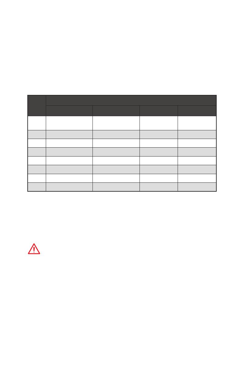
3. Rotate the GAME BOOST knob to select the overclocking stage as you desire.
Stage
CPU Frequency
i3-8350K i5-8600K i7-8700K i7-8086K
0
GAME BOOST
Disabled
GAME BOOST
Disabled
GAME BOOST
Disabled
GAME BOOST
Disabled
1 4.1 GHz 4.2~4.4 GHz 4.4~4.8 GHz 4.4~5.1 GHz
2 4.2 GHz 4.3~4.5 GHz 4.5~4.9 GHz 4.5~5.2 GHz
4 4.3 GHz 4.4~4.6 GHz 4.6~5.0 GHz 4.6~5.3 GHz
6 4.4GHz 4.5~4.7 GHz 4.7~5.1 GHz 4.7~5.4 GHz
8 4.5 GHz 4.6~4.8 GHz 4.8~5.2 GHz 4.8~5.5 GHz
10 4.6 GHz 4.7~4.9 GHz 4.9~5.3 GHz 4.9~5.6 GHz
11 4.7 GHz 4.8~5.0 GHz 5.0~5.4 GHz 5.0~5.7 GHz
4. Power on and then GAME BOOST will automatically overclock processor depending
on the stage you selected.
To disable GAME BOOST:
1. Set the GAME BOOST knob to HW mode in BIOS Setup.
2. Power off the computer.
3. Rotate the GAME BOOST knob to 0 and then power on. The configuration
parameters will be returned to default values.
Important
y
When enabling GAME BOOST mode, it is recommended to use liquid CPU cooler with
dual fan radiator for better cooling and performance.
y
You can also control the GAME BOOST function in BIOS Setup.
y
In order to optimize performance and improve system stability, when you activate the
GAME BOOST function, please leave the settings in the BIOS > OC menu unchanged.
y
The success of overclocking depends on the components of your computer.
y
We do not guarantee the GAME BOOST overclocking range or the damages/ risks
caused by overclocking behavior.
y
MSI components are recommended for better compatibility when using GAME
BOOST function.
25
Overview of Components
24
131
12
ATX_PWR1
1 +3.3V 13 +3.3V
2 +3.3V 14 -12V
3 Ground 15 Ground
4 +5V 16 PS-ON#
5 Ground 17 Ground
6 +5V 18 Ground
7 Ground 19 Ground
8 PWR OK 20 Res
9 5VSB 21 +5V
10 +12V 22 +5V
11 +12V 23 +5V
12 +3.3V 24 Ground
5
4 1
8
CPU_PWR1/ CPU_PWR2
1 Ground 5 +12V
2 Ground 6 +12V
3 Ground 7 +12V
4 Ground 8 +12V
Important
Make sure that all the power cables are securely connected to a proper ATX power
supply to ensure stable operation of the motherboard.
CPU_PWR1~2, ATX_PWR1: Power Connectors
These connectors allow you to connect an ATX power supply.
V-Check Points
These voltage checkpoints are used to measure the current system voltages. A
multimeter (not included) will be required to check voltages. To measure voltage,
place test leads on the GND (screw mounting hole) and a V-Check Point. Please refer
to the manual of your multimeter for more information.
VCCIO
PCH
V
CCSA
DDR
CPU
34
Onboard LEDs
LED color Fan control mode
Red PWM mode
White DC mode
Fan LEDs
These LEDs indicate the fan control mode.
CPU_FAN1 LED
PUMP_FAN1 LED
GAME BOOST LEDs
These LEDs indicate GAME BOOST control status.
SW GAME BOOST LED (White)
HW GAME BOOST LED (Red)
  • Page 1 1
  • Page 2 2
  • Page 3 3
  • Page 4 4
  • Page 5 5
  • Page 6 6
  • Page 7 7
  • Page 8 8
  • Page 9 9
  • Page 10 10
  • Page 11 11
  • Page 12 12
  • Page 13 13
  • Page 14 14
  • Page 15 15
  • Page 16 16
  • Page 17 17
  • Page 18 18
  • Page 19 19
  • Page 20 20
  • Page 21 21
  • Page 22 22
  • Page 23 23
  • Page 24 24
  • Page 25 25
  • Page 26 26
  • Page 27 27
  • Page 28 28
  • Page 29 29
  • Page 30 30
  • Page 31 31
  • Page 32 32
  • Page 33 33
  • Page 34 34
  • Page 35 35
  • Page 36 36
  • Page 37 37
  • Page 38 38
  • Page 39 39
  • Page 40 40
  • Page 41 41
  • Page 42 42
  • Page 43 43
  • Page 44 44
  • Page 45 45
  • Page 46 46
  • Page 47 47
  • Page 48 48
  • Page 49 49
  • Page 50 50
  • Page 51 51
  • Page 52 52
  • Page 53 53
  • Page 54 54
  • Page 55 55
  • Page 56 56
  • Page 57 57
  • Page 58 58
  • Page 59 59
  • Page 60 60
  • Page 61 61
  • Page 62 62
  • Page 63 63
  • Page 64 64
  • Page 65 65
  • Page 66 66
  • Page 67 67
  • Page 68 68
  • Page 69 69
  • Page 70 70
  • Page 71 71
  • Page 72 72
  • Page 73 73
  • Page 74 74
  • Page 75 75
  • Page 76 76
  • Page 77 77
  • Page 78 78
  • Page 79 79
  • Page 80 80
  • Page 81 81
  • Page 82 82
  • Page 83 83
  • Page 84 84
  • Page 85 85
  • Page 86 86
  • Page 87 87
  • Page 88 88
  • Page 89 89
  • Page 90 90
  • Page 91 91
  • Page 92 92
  • Page 93 93
  • Page 94 94
  • Page 95 95
  • Page 96 96
  • Page 97 97
  • Page 98 98
  • Page 99 99
  • Page 100 100
  • Page 101 101
  • Page 102 102
  • Page 103 103
  • Page 104 104
  • Page 105 105
  • Page 106 106
  • Page 107 107
  • Page 108 108
  • Page 109 109
  • Page 110 110
  • Page 111 111
  • Page 112 112
  • Page 113 113
  • Page 114 114
  • Page 115 115
  • Page 116 116
  • Page 117 117
  • Page 118 118
  • Page 119 119
  • Page 120 120
  • Page 121 121
  • Page 122 122
  • Page 123 123
  • Page 124 124
  • Page 125 125
  • Page 126 126
  • Page 127 127
  • Page 128 128
  • Page 129 129
  • Page 130 130
  • Page 131 131
  • Page 132 132
  • Page 133 133
  • Page 134 134
  • Page 135 135
  • Page 136 136
  • Page 137 137
  • Page 138 138
  • Page 139 139
  • Page 140 140
  • Page 141 141
  • Page 142 142
  • Page 143 143
  • Page 144 144
  • Page 145 145
  • Page 146 146
  • Page 147 147
  • Page 148 148
  • Page 149 149
  • Page 150 150
  • Page 151 151
  • Page 152 152
  • Page 153 153
  • Page 154 154
  • Page 155 155
  • Page 156 156
  • Page 157 157
  • Page 158 158
  • Page 159 159
  • Page 160 160
  • Page 161 161
  • Page 162 162
  • Page 163 163
  • Page 164 164
  • Page 165 165
  • Page 166 166
  • Page 167 167
  • Page 168 168
  • Page 169 169
  • Page 170 170
  • Page 171 171
  • Page 172 172
  • Page 173 173
  • Page 174 174
  • Page 175 175
  • Page 176 176
  • Page 177 177
  • Page 178 178
  • Page 179 179
  • Page 180 180
  • Page 181 181
  • Page 182 182
  • Page 183 183
  • Page 184 184
  • Page 185 185
  • Page 186 186
  • Page 187 187
  • Page 188 188
  • Page 189 189
  • Page 190 190
  • Page 191 191
  • Page 192 192
  • Page 193 193
  • Page 194 194
  • Page 195 195
  • Page 196 196
  • Page 197 197
  • Page 198 198
  • Page 199 199
  • Page 200 200
  • Page 201 201
  • Page 202 202
  • Page 203 203
  • Page 204 204
  • Page 205 205
  • Page 206 206
  • Page 207 207
  • Page 208 208
  • Page 209 209
  • Page 210 210
  • Page 211 211
  • Page 212 212
  • Page 213 213
  • Page 214 214
  • Page 215 215
  • Page 216 216
  • Page 217 217
  • Page 218 218
  • Page 219 219
  • Page 220 220
  • Page 221 221
  • Page 222 222
  • Page 223 223
  • Page 224 224
  • Page 225 225
  • Page 226 226
  • Page 227 227
  • Page 228 228

MSI MEG Z390 ACE Инструкция по применению

Категория
Материнские платы
Тип
Инструкция по применению
Это руководство также подходит для

Задайте вопрос, и я найду ответ в документе

Поиск информации в документе стал проще с помощью ИИ