Alphard AAB-1200.2D Two-Channel Amplifiers Инструкция по применению

Тип
Инструкция по применению

Alphard AAB-1200.2D Two-Channel Amplifiers — это высококачественные и технически совершенные продукты, обладающие широкими возможностями и вариантами использования. Усилитель имеет встроенные фильтры высоких и низких частот, а также регулировку уровня баса. Это позволяет настроить звук в соответствии с вашими предпочтениями и акустическими характеристиками салона автомобиля. Усилитель может работать в двухканальном режиме или в режиме моста, что позволяет подключить к нему сабвуфер или несколько динамиков.

Alphard AAB-1200.2D Two-Channel Amplifiers — это высококачественные и технически совершенные продукты, обладающие широкими возможностями и вариантами использования. Усилитель имеет встроенные фильтры высоких и низких частот, а также регулировку уровня баса. Это позволяет настроить звук в соответствии с вашими предпочтениями и акустическими характеристиками салона автомобиля. Усилитель может работать в двухканальном режиме или в режиме моста, что позволяет подключить к нему сабвуфер или несколько динамиков.

TWO-CHANNEL AMPLIFIERS
ДВУХКАНАЛЬНЫЕ УСИЛИТЕЛИ
HTTPS://ALPHARD.AUDIO
AAB-1200.2D AAB-1800.2D CLASS D
1. Before installing the amplifier disconnect the battery from the electrical system.
2. To connect the amplifier it is necessary to stretch the power cable from the location of the battery to the place of installation
of the amplifier. Select the power cable with the appropriate regulations in AWG (see Table: Selection of the diameter of the
power cables)
3. Connect the power supply with the correct polarity. Connect all (+) terminals of the amplifier to the cables stretching from
the positive terminal of the battery and all (-) terminals of the amplifier to the cables stretching from the negative terminal of the
battery.
4. Place the fuse holder for each positive cable within 40 cm from the positive terminal of the battery and connect one end of
the power cable to the holder after connecting the other end to the amplifier. Do not install the fuse(s).
5. Route all signal cables next to each other and separately from the power cables.
6. Connect the wires of RCA input. The input signal power must be between 0.2 V and 6 V.
7. To connect the power wire supply is necessary to use special power cables.
8. Fasten the amplifier properly when installing it in the vehicle. If the component is disconnected during driving, it may cause
serious damage to the passengers of the vehicle or another vehicle. It is not recommended to screw the amplifier directly to the
metal it can lead to distorsions at the signal outputs.
9. After installation is complete, check the wiring of the system and make sure that all connections have been made correctly.
Before installing the fuses, disconnect the positive lead from the battery and then install the fuse in the fuse holder. Using the
light bulb 12 V 21 W, connect the positive lead to one contact of the bulb and the other contact of the bulb to the positive
terminal of the battery.
When properly connected, the bulb must briefly light up and go out. Now you may connect the positive lead to the (+) of the
battery. If the light does not go out, then something is wrong. This will prevent damage to the amplifier in case of reverse polarity
and unwanted sparks when connecting. Install the rest of the fuses.
10. To activate the amplifier, it is necessary to apply the positive potential of 12 volts to the control input of the amplifier (REM
IN) through a switch or a corresponding control output (REMOTE OUT) with the head unit (HU).
11. LED indicator on front of the amplifier turns blue to indicate that the amplifier is turned on. If the indicator does not light
up see chapter "Possible faults and their solutions" for more information.
12. The sound level is calibrated by adjusting the volume of the source up to 3/4 of its maximum level. Then, adjust the
sensitivity level of the amplifier up until you hear distortions.
4
EN
5 . W I R I N G D I A G R A M S
Connect the speaker cables from the positive and negative terminals of the speakers to the respective outputs of the amplifier
terminal marked with CH1 / CH2 SPEAKERS OUTPUTS, as shown at the diagram. To connect the power wire supply it is
necessary to use special power cables. The fuse is placed in the holder and fixed in the cable cut. One end of the cable is
connected to the positive terminal of the battery, the second one to the amplifier terminals marked with +12V. Be sure to use a
fuse with the parameters sufficient for use in the system. The length and diameter of the grounding cable must conform to the
length and diameter of the cable +12V. Connect one end to the negative terminal of the battery and the other end of the
grounding cable to the terminals marked with GND. Connect the head unit (HU) to low-level inputs of the amplifier using RCA
cable.
Step 1. Connect the speaker cable from (+) terminal of the amplifier to (+) terminal of the speaker.
Step 2. Connect the speaker cable from (-) terminal of the amplifier to (-) terminal of the speaker.
Step 3. Repeat the installation sequence Step 1 and Step 2 for each speaker.
Standard wiring diagram of two-channel amplifier to two speakers.
1-8 Ohm 1-8 Ohm
Caution!!! The minimum permissible connection load impedance at every single channel is 1 Ohm.
For models AAB-1200.2D, AAB-1800.2D the operating voltage is 9-15V.
Step 1. Connect the speaker cable from (+) terminal of the amplifier to (+) terminal of the subwoofer.
Step 2. Connect the speaker cable from (-) terminal of the amplifier to (-) terminal of the subwoofer.
Step 1. Connect one end of the power cable from (+) terminal of the battery and the second end to the amplifier terminal marked
with +12V. Do not forget to protect positive power cable with appropriate fuse.
Step 2. Connect one end of the power cable from (-) terminal of the battery and the second end of the grounding cable to the
terminals marked with GND.
Step 3. Connect one end of the cable to the Remote output terminal at the HU and the second end to the amplifier terminal marked
with REM.
Standard wiring diagram of two-channel amplifier to one subwoofer
Standard wiring diagram of two-channel amplifier to battery
5/FL
Step 1. Connect one end of the RCA cable to the RCA output terminals at the HU and the second end to the amplifier
RCA inputs terminals marked with INPUT.
Standard wiring diagram of two-channel amplifier to Head Unit
Caution!!! The minimum permissible connection load impedance for bridged connection is 2 Ohm.
For models AAB-1200.2D, AAB-1800.2D the operating voltage is 9-15 V.
min. 2 Ohm
4 Ohm 8 Ohm
Voice coil Total impedance
8 Ohm 16 Ohm
1 2 3
7
8
9
4 5 10 11 12 13
6
1. INPUT – signal input, RCA jacks
2. CROSSOVER HPF High pass filter (15 Hz 1 kHz at 12 dB/Oct)
3. CROSSOVER LPF low pass filter (50 Hz 20 kHz at 12 dB/Oct)
4. GAIN – input signal level adjustment
5. BASS BOOST - bass level adjustment (0-12 dB at 45 Hz)
6. REMOTE – input for connection of the bass remote control
7. POWER - LED for operation (blue)
8. CLIP - LED on the clip (orange)
9. PROTECT - LED for protection (red)
10. SPEAKERS OUTPUTSspeakers connection terminals
11. +12Vpower supply terminal (+12V)
12. REM IN – connector of remote activation of the amplifier
13. GNDgrounding supply terminal «-»
14. POWER – LED for operation (blue)
15. GAIN – input signal level adjustment
R em o t e co n t ro l
14 15
4 Ohm 12 Ohm
Voice coil Total impedance
8 Ohm 24 Ohm
4 Ohm 16 Ohm
Voice coil Total impedance
8 Ohm 32 Ohm
4 Ohm 2 Ohm
Voice coil Total impedance
8 Ohm 4 Ohm
4 Ohm 1.33 Ohm
Voice coil Total impedance
8 Ohm 2.66 Ohm
4 Ohm 1 Ohm
Voice coil Total impedance
8 Ohm 2 Ohm
4 Ohm 4 Ohm
Voice coil Total impedance
8 Ohm 8 Ohm
Deaf Bonce amplifiers are high-quality and technically perfect products. The problems often arise due to improper use, faulty
connection of components or lack of power supply of the on-board network.
1) The amplifier does not turn on.
Problem solution: Check all the contacts and the presence of 9-15 V at the amplifier terminals. Check whether the control input
of the amplifier "REM IN" receives the positive potential of +12 V.
2) Power turns on, but goes into protection (protection indicator lights up)
Problem solution: Check if there is a short circuit (fault) on the amplifier output which is connected to the speakers or
subwoofers. Make sure that commutation of the voice coils of the subwoofer is correct. The rated impedance of the voice coils
should not be lower than the permissible rated load impedance of the amplifier. Check the supply voltage of the amplifier. It must
be within the range of 9-15 V.
3) The amplifier turns on but at a high volume it goes in to protection. Problem solution: The amplifier may lack power. Make
sure that the rated current of the alternator and the battery capacity is enough to power this amplifier.
Check the amplifier for overheating. Check the load impedance.
4) The amplifier is turned on, but there is no sound from the speakers or subwoofer.
Problem solution: Check the connection of the amplifier, the integrity of the interconnecting cable, HU, the speakers or the
subwoofer.
Power RMS 4 Ohm* (W)
Power RMS 2 Ohm* (W)
Low pass filter (Hz)
Frequency response (Hz)
Input sensitivity (V)
Signal to noise ratio (dB)
Model
Input terminal connection (AWG/ )mm²
Output terminal connection mm²(AWG/ )
Working voltage (V)
High pass filter (Hz)
Size (LхWхH inch)
Minimum permissible load impedance on the single channel (Ohm)
Crossover (dB/Oct)
*RMS Power at 14.4 V, THD 1%
Minimum permissible load impedance in bridged mode (Ohm)
Size (LхWхH mm)
Power RMS 2 Ohm bridged mode* (W)
Bass level adjustment (dB at 45 Hz)
Damping factor
Power RMS 1 Ohm* (W)
Power RMS 4 Ohm bridged mode* (W)
The simultaneous operation of LPF and HPF
580 x 2
780 x 2
AAB-1200.2D
2 420 х 1
15 - 1 000
50 - 20 000
0-12
12
15 - 20 000
0.2 - 6
100
1
8 / 8.37
9-15
215 x 247 х 73,5
2
8.46 x 9.72 х 2.89
2 / 33.6
>260
1 210 x 2
1 560 х 1
Yes
670 x 2
1 020 x 2
AAB-1800.2D
3 600 х 1
15 - 1 000
50 - 20 000
0-12
12
15 - 20 000
0.2 - 6
100
1
8 / 8.37
9-15
282 x 247 х 73.5
2
11.1 x 9.72 х 2.89
0 / 53.5
> 260
1 800 x 2
2 020 х 1
Yes
9 . B O X C O N T E N T S EN
1 1 . I N F O R M A T I O N O N D I S P O S A L O F T H E E L E C T R I C A L A N D
E L E C T R O N I C E Q U I P M E N T ( F O R T H E E U R O P E A N C O U N T R I E S W I T H
S E P A R A T E W A S T E C O L L E C T I O N )
1 0 . W A R R A N T Y A N D M A I N T E N A N C E I N F O
Deaf Bonce products are warranted against defects concerning materials and their manufacturing under normal functioning
conditions.
While the product is under warranty, defective parts will be repaired or replaced at the manufacturer's discretion. The
defective product, along with notification about it, must be returned to the dealer from which it was purchased together with the
warranty certificate duly filled in, . If the product is no longer under warranty, it will be complete with the original packaging
repaired at the current costs.
Our company does not undertake any liability for damages due to transportation. Our company does not take any
responsibility for: costs or loss of profit due to the impossibility to use the product, other accidental or consequential costs,
expenses or damages suffered by the customer. Warranty according to laws in force.
For more information visit our website and carefully read warranty card. The manufacturer reserves the right to change design
1. Amplifier 1 pc.
2. Owner's manual 1 pc.
3. Warranty card 1 pc.
4. Remote control 1 pc.
5. Mounting Kit 1 pc.
6. Window decals - 2 pcs.
9. После завершения установки проверьте электропроводку системы и убедитесь в том, что все подключения были
выполнены правильно. Перед установкой предохранителя, отключите плюсовой кабель от АКБ, установите предохранитель
в держатель предохранителя. При помощи лампочки 12 В 21 Вт подключите плюсовой кабель к одному контакту лампочки,
а второй оставшийся контакт лампочки к плюсовой клемме АКБ.
При правильном подключении лампочка должна кратковременно загореться и погаснуть. Теперь можно подключить
плюсовой кабель к + АКБ. Если лампочка не гаснет, значит что то сделано неправильно. Это позволит избежать выхода из
строя усилителя при переполюсовке и нежелательных искр при подключении. Установите оставшиеся предохранители.
10. Для включения усилителя, необходимо на управляющий вход усилителя (REM IN) подать положительный потенциал
+12 В через тумблер , либо соответствующий управляющий выход (REMOTE OUT) с головного устройства (ГУ).
11. Индикатор LED на передней панели усилителя загорится синим показывая, что усилитель включен. В случае если
индикатор не загорелся перейдите в раздел «Возможные неисправности и их решения» для получения дополнительной
информации.
12. Калибровка уровня звука производится путем настройки уровня громкости источника на 3/4 его максимального
уровня; затем, путем регулировки уровня входной чувствительности усилителя до тех пор, пока Вы не услышите искажения.
15
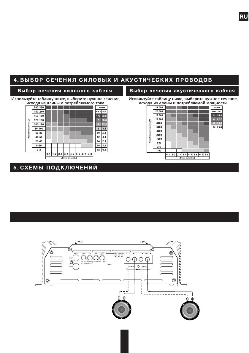
Подключите акустические провода от плюсовых и минусовых клемм динамиков, к соответствующим выходам на
терминале усилителя, обозначенные CH1 / CH2 SPEAKERS OUTPUTS, как показано на схеме. Для подключения питания
необходимо использовать специализированные силовые провода, предохранитель помещается в держатель и
устанавливается в разрез кабеля, один конец которого подключается к плюсовой клемме АКБ, второй к клеммам
усилителя, обозначенным +12V. Обязательно используйте предохранители с параметрами, достаточными для
применения в системе. Длина и сечение кабеля заземления должны соответствовать длине и сечению кабеля +12V.
Один конец подключите к минусовой клемме АКБ, другой конец кабеля заземления подключите к клеммам,
обозначенным GND. Подключите ГУ к низкоуровневым входам усилителя при помощи RCA кабеля.
Шаг 1. Подключите акустический кабель от (+) клеммы усилителя к (+) клемме динамика.
Шаг 2. Подключите акустический кабель от (-) клеммы усилителя к (-) клемме динамика.
Шаг 3. Повторить Шаг 1 и Шаг 2 для каждого диамика
Стандартная схема подключения двух канального усилителя к двум динамикам.
1-8 Ом
Внимание!!! Минимально допустимое сопротивление при поканальном включении - 1 Ом на каждый из каналов усилителя.
Для моделей AAB-1200.2D, AAB-1800.2D рабочее напряжение составляет 9-15 В.
1-8 Ом
16
RU
Шаг 1. Подключите акустический кабель от (+) клеммы усилителя к (+) клемме сабвуфера.
Шаг 2 . Подключите акустический кабель от (-) клеммы усилителя к (-) клемме сабвуфера.
Шаг 1. Один конец силового кабеля подключите к (+) клемме АКБ, второй к клемме усилителя, обозначенной +12V. Не
забудьте защитить плюсовой силовой кабель предохранителем соответствующего номинала.
Шаг 2. Один конец силового кабеля подключите к (-) клемме АКБ, второй конец силового кабеля заземления подключите
к клеммам, обозначенным GND.
Шаг 3. Один конец кабеля подключите к клемме выхода Remote на ГУ, второй конец к клемме усилителя, обозначенной
REM.
Шаг 1. Один конец кабеля RCA подключите к клеммам выходов RCA на ГУ, второй конец к входам RCA на усилителе,
обозначенным INPUT.
Стандартная схема подключения двухканального усилителя к АКБ
Стандартная схема подключения двухканального усилителя к ГУ
Внимание!!! Минимально допустимое сопротивление для мостового включения - 2 Ом.
Для моделей AAB-1200.2D, AAB-1800.2D рабочее напряжение составляет 9-15 В.
мин. 2 Ом
5/FL
не более, чем 40 см
Предохранитель
Аккумулятор
1. INPUT – RCA разъемы для подключения низкоуровневых источников
сигнала, линейные входы RCA
2. CROSSOVER HPF фильтр высоких частот (15 Гц 1 кГц при 12 дБ/Окт)
3. CROSSOVER LPF фильтр низких частот (50 Гц 20 кГц при 12 дБ/Окт)
4. GAIN – регулировка уровня входного сигнала
5. BASS BOOST регулировка уровня подъема басса (0-12 дБ при 45 Гц)
6. REMOTE – вход подключения дистанционного регулятора баса
7. POWER – индикатор работы (синий)
8. CLIP - индикатор по клиппу (оранжевый)
9. PROTECT - индикатор защиты (красный)
10. SPEAKERS OUTPUTS – терминалы подключения динамиков
11. +12V – терминал подключения питания (+12В)
12. REM IN терминал подключения дистанционного включения усилителя
13. GND терминал подключения заземления «-»
14. POWER – индикатор работы (синий)
15. GAIN – регулировка уровня входного сигнала
R em o t e co n t ro l
14 15
1 2 3
7
8
9
4 5 10
611 12 13
  • Page 1 1
  • Page 2 2
  • Page 3 3
  • Page 4 4
  • Page 5 5
  • Page 6 6
  • Page 7 7
  • Page 8 8
  • Page 9 9
  • Page 10 10
  • Page 11 11
  • Page 12 12
  • Page 13 13
  • Page 14 14
  • Page 15 15
  • Page 16 16
  • Page 17 17
  • Page 18 18
  • Page 19 19
  • Page 20 20
  • Page 21 21
  • Page 22 22
  • Page 23 23
  • Page 24 24

Alphard AAB-1200.2D Two-Channel Amplifiers Инструкция по применению

Тип
Инструкция по применению

Alphard AAB-1200.2D Two-Channel Amplifiers — это высококачественные и технически совершенные продукты, обладающие широкими возможностями и вариантами использования. Усилитель имеет встроенные фильтры высоких и низких частот, а также регулировку уровня баса. Это позволяет настроить звук в соответствии с вашими предпочтениями и акустическими характеристиками салона автомобиля. Усилитель может работать в двухканальном режиме или в режиме моста, что позволяет подключить к нему сабвуфер или несколько динамиков.

Задайте вопрос, и я найду ответ в документе

Поиск информации в документе стал проще с помощью ИИ

на других языках