Sanus VLF510 Руководство пользователя
- Тип
- Руководство пользователя

Customer Service
Americas: 800-359-5520 • 952-225-6013 • info@sanus.com
UK: 0800 056 2853
Europe, Middle East, and Africa: +31 (0) 495 580 852 • europe[email protected]om
Asia Paci c: 86 755 8996 9226 • sanus.ap@milestone.com
SANUS • 6436 City West Parkway • Eden Prairie, MN 55344 USA
©2013 Milestone AV Technologies. All rights reserved. Sanus is a division of Milestone.
All other brand names or marks are used for identi cation purposes and are trademarks of their respective owners.
We are here
to help!
Please contact
Customer
Service with
any questions.
VLF510
Instruction Manual
Installation
video available at
Sanus.com
sanus.com
6901-002284 00

2
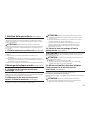
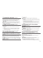
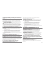
Before You Begin
WARNING: This product contains a magnet. If an implanted medical device such as a pacemaker or implantable
cardioverter de brillator (ICD) is in use, magnetic elds may a ect the operation of those devices, resulting in serious injury
or death. If you have an implanted medical device, keep at least 13 cm (5 in.) between your device and the magnet. Please
consult with your physician or medical professional prior to using this product.
CAUTION: Avoid potential personal injuries and property damage!
Refer to the documentation that came with your TV for additional considerations
Do not use this product for any purpose not explicitly speci ed by manufacturer
The wall must be capable of supporting ve times the weight of the monitor and mount combined
This product is not designed for use in metal stud walls
If you do not understand these instructions, or have doubts about the safety of the installation, assembly or use of this
product, contact Customer Service or call a quali ed contractor
Manufacturer is not responsible for damage or injury caused by incorrect assembly or use
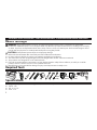
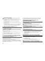
Required Tools
13mm
(1/2 in.)
5.5mm
(7/32 in.)
10mm
(3/8 in.)
Specifications
Weight capacity-DO NOT EXCEED: 57 kg (125 lb.) includes TV and any accessories
Swivel: ±30°
Tilt: +0° to –10°
Level: ±1.5°
IMPORTANT SAFETY INSTRUCTIONS – SAVE THESE INSTRUCTIONS – PLEASE READ ENTIRE MANUAL PRIOR TO USE

3
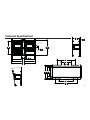
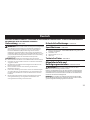
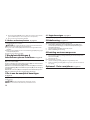
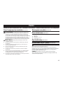
Technical Specifications
4.80
121.9
6.18
156.9
30.60
777.2
16.54
420.0
29.22
742.2
32.16
816.9
20.34
516.5
2.14
54.4
MONITOR BRACKET
CENTER
WALL PLATE
CENTER
4.00
101.6
10.80
274.3
18.80
477.5
14.80
375.9
22.80
579.1
8.98
228.0
12.31
312.6
13.51
343.0
1.54
39.2
10.29
261.3
10.00°

4
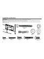
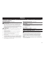
M4 M6/M8
M4 x 12 mm
M4 x 30 mm
M6 x 14 mm M6 x 40 mm
M8 x 16 mm
5/16 x 2¾ in.
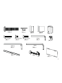
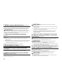
Supplied Parts and Hardware
WARNING: This product contains small items that could be a choking hazard if swallowed.
Before starting assembly, verify all parts are included and undamaged. If any parts are missing or damaged, do not return the
damaged item to your dealer; contact Customer Service. Never use damaged parts!
NOTE: M4, M6, or M8 describes the diameter, mm describes the length of screws that are labeled M# X ##mm. Not all hardware
included will be used.
[01] x 1
[02] x 2
[03] x 4
[04] x 4
[05] x 4
[06] x 4
[07] x 4
[08] x 4 [09] x 4
[10] x 4
[11] x 4
[12] x 4

5
M8 x 40 mm
14 mm 24 mm
3mm
M4 x 25mm
10-32 x 3/8 in.
10-32 x 3/4 in.
1/8 in.
5/32 in.
[13] x 4
[14] x 4
[15] x 4 [16] x 4
[17] x 1
[18] x 2
[19] x 2
[20] x 8 [21] x 1
[22] x 2
[23] x 1
[24] x 1
[25] x 2
[26] x 1
[27] x 1

6
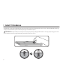
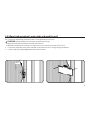
1 Select TV Hardware
Hand thread screws into the threaded inserts on the back of your TV to determine the correct screw diameter (M4, M6, or M8). Try
using a screw alone first. If you need more space, try a screw with a spacer.
CAUTION: Avoid potential personal injuries and property damage! Using hardware that is too long may damage your TV. If
you encounter resistance, stop immediately and contact customer service.
OR

7
1-1 Attach brackets to TV
Using the hardware you selected in step 1, attach the brackets to your TV.
A. Use option A if your TV has a flat/unobstructed back.
B. Use option B if your TV has an irregular back, recessed mounting holes,
or if you need more room for cables, recesses, or protrusions.
Confirm that the brackets are level on the back of the TV.
OR
A
B
B
[08] [10] [12]
[06] [07]
[02]
[02]
[09] [11] [13]
[06] [07]
[15] [16]
[14]
[14]
[02]
[15] [16]

8
Slide the arms of the wall plate [01] together and insert the slide lock [17] into place. This will lock the arms into full extension
making the wall plate mounting and TV attachment easier.
[01]
[17]
[01]
[17]
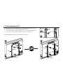
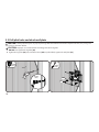
2 Mount the Wall Plate
2-1 Prepare the Wall Plate for Mounting

9
2-2 (Wood stud mounting) Locate studs and mark the wall
For assistance in determining wall plate location, see Height Finder at sanus.com.
CAUTION: Avoid potential personal injuries and property damage!
Drywall covering the wall must not exceed 16 mm (5/8 in.)
Minimum wood stud size: common 51 x 102 mm (2 x 4 in.) nominal 38 x 89 mm (1/ x 3/ in.)
1. Locate studs. Verify the center of the stud with an awl or thin nail or use an edge to edge stud finder.
2. Level the wall plate template [27] and mark the hole locations.
≤ 16 mm
(5/8 in.)
[27]

10
75 mm
(3 in.)
[04]
CAUTION: Avoid potential injuries or property damage! Pilot holes MUST be drilled to a depth of 75 mm (3 in.), using a 5.5
mm (7/32 in.) diameter drill bit.
CAUTION:
Improper use could reduce the holding power of the lag bolt.
DO NOT over-tighten the lag bolts [03].
Tighten the lag bolts [03] only until the washers [04] are pulled firmly against the wall plate [01].
2-3 Drill pilot holes and attach wall plate
5.5 mm
(7/32 in.)
[03]
13 mm
(1/2 in.)

11
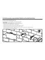
For assistance in determining wall plate location, see Height Finder at sanus.com.
See step 2-1 before performing this step.
Level the wall plate template [27] and mark the hole locations.
CAUTION:
Avoid potential injuries or property damage!
Mount the wall plate [01] directly onto the concrete surface
Minimum solid concrete thickness: 203mm (8 in.)
Minimum concrete block size: 203 x 203 x 406 mm (8 x 8 x 16 in.)
Minimum horizontal space between fasteners: 406 mm (16 in.)
Pilot holes MUST be drilled to a depth of 75 mm (3 in.) using a 10 mm (3/8 in.) diameter drill bit
Never drill into the mortar between blocks
2-2 (Solid concrete or concrete block) Mark the wall and drill pilot holes
[27]
75 mm
(3 in.)
10 mm
(3/8 in.)

12
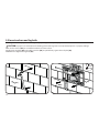
Insert lag bolt anchors [05]. Then insert lag bolts [03] through the wall plate [01] and into the anchors.
CAUTION:
Improper use could reduce the holding power of the lag bolt. To avoid potential injuries or property damage:
Be sure the anchors [05] are seated flush with the concrete surface
Tighten the lag bolts [03] only until the washers [04] are pulled firmly against the wall plate [01]
DO NOT over-tighten the lag bolts [03]
2-3 Insert anchors and lag bolts
[05]
[05]
[01]
[03]
[04]
13 mm
(1/2 in.)

13

14
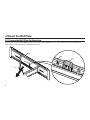
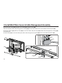
3 Install Wall Plate Covers & Cable Management Assembly
Mount the upper cover [25] using the ⁄ in. hex key [21] and four screws [20].
Place the rear plate of the cable management assembly [26] over the two smallest holes in the bottom of the wall plate [01].
Use the ⁄ in. hex key [21] and four screws [20] to secure the lower wall plate cover [25] and the cable management assembly [26]
to the wall plate.
Use two screws [19] to secure the front plate of the cable management assembly [26] to the inside of the TV interface [01].
[25]
[20]
[19]
[26]
[01]
[26]
[21]
[20]
[01]
[25]
[26]

15
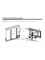
Be sure to hook the TV brackets onto the interface, as shown.
CAUTION:
Avoid potential injuries or property damage! HEAVY! You will need assistance with this step.
4 Attach TV to Wall Plate Assembly
[02]
[02]
[01]

16
[22]
[18]
[01]
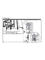
4-1 Attach caps
Attach click caps [22] to the interface [01] using
screws [18].
[24]

17
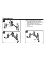
Plug the required wires and/or cables into the TV.
1. Slide the three covers of the cable managment
assembly [26] o the front (face plate mount), rear
(wall plate mount), and center ( oating).
2. Route the wires and/or cables through the three
sections.
3. Replace the covers.
1
2
3
5 Manage Cables
[26]
[26]
[26]

18
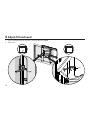
6 Adjust Tilt and Level
[23]
1. Adjust up/down tilt tension by hand or using the M3 hex key [24].
2. Adjust level.
[24]

19
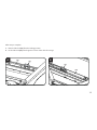
After setup is complete:
A. Remove slide lock [17] from the locking position.
B. Fit the slide lock [17] into the grooves of one of the slides for storage.
A
B
[17]
[01]
[01]
[17]

20
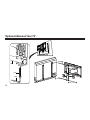
Optional-Remove Your TV
[22]
[18]
[01]
[24]
Страница загружается ...
Страница загружается ...
Страница загружается ...
Страница загружается ...
Страница загружается ...
Страница загружается ...
Страница загружается ...
Страница загружается ...
Страница загружается ...
Страница загружается ...
Страница загружается ...
Страница загружается ...
Страница загружается ...
Страница загружается ...
Страница загружается ...
Страница загружается ...
Страница загружается ...
Страница загружается ...
Страница загружается ...
Страница загружается ...
Страница загружается ...
Страница загружается ...
Страница загружается ...
Страница загружается ...
Страница загружается ...
Страница загружается ...
Страница загружается ...
Страница загружается ...
Страница загружается ...
Страница загружается ...
Страница загружается ...
Страница загружается ...
Страница загружается ...
Страница загружается ...
Страница загружается ...
Страница загружается ...
Страница загружается ...
Страница загружается ...
Страница загружается ...
Страница загружается ...
-
 1
1
-
 2
2
-
 3
3
-
 4
4
-
 5
5
-
 6
6
-
 7
7
-
 8
8
-
 9
9
-
 10
10
-
 11
11
-
 12
12
-
 13
13
-
 14
14
-
 15
15
-
 16
16
-
 17
17
-
 18
18
-
 19
19
-
 20
20
-
 21
21
-
 22
22
-
 23
23
-
 24
24
-
 25
25
-
 26
26
-
 27
27
-
 28
28
-
 29
29
-
 30
30
-
 31
31
-
 32
32
-
 33
33
-
 34
34
-
 35
35
-
 36
36
-
 37
37
-
 38
38
-
 39
39
-
 40
40
-
 41
41
-
 42
42
-
 43
43
-
 44
44
-
 45
45
-
 46
46
-
 47
47
-
 48
48
-
 49
49
-
 50
50
-
 51
51
-
 52
52
-
 53
53
-
 54
54
-
 55
55
-
 56
56
-
 57
57
-
 58
58
-
 59
59
-
 60
60


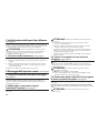
Sanus VLF510 Руководство пользователя
- Тип
- Руководство пользователя
Задайте вопрос, и я найду ответ в документе
Поиск информации в документе стал проще с помощью ИИ
на других языках
- English: Sanus VLF510 User manual
- français: Sanus VLF510 Manuel utilisateur
- italiano: Sanus VLF510 Manuale utente
- español: Sanus VLF510 Manual de usuario
- Deutsch: Sanus VLF510 Benutzerhandbuch
- Nederlands: Sanus VLF510 Handleiding
- português: Sanus VLF510 Manual do usuário
- polski: Sanus VLF510 Instrukcja obsługi
- čeština: Sanus VLF510 Uživatelský manuál
- svenska: Sanus VLF510 Användarmanual
- suomi: Sanus VLF510 Ohjekirja
Похожие модели бренда
-
Sanus LL11 Руководство пользователя
-
-
-
 Sanus VisionMount VML10 Руководство пользователя
-
Sanus Systems Vll10 Руководство пользователя
-
-
-
-
-

