Generac 8 kVA 0059140 Руководство пользователя
- Категория
- Генераторы
- Тип
- Руководство пользователя

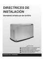
INSTALLATION
GUIDELINES
50 Hertz Air-cooled Generators
www.generac.com or 1-262-506-6073
NOT INTENDED FOR USE IN CRITICAL LIFE SUPPORT
APPLICATIONS.
ONLY QUALIFIED ELECTRICIANS OR CONTRACTORS
SHOULD ATTEMPT INSTALLATION!
DEADLY EXHAUST FUMES! OUTDOOR INSTALLATION
ONLY!

TABLE OF CONTENTS
Introduction ......................................................... Inside Front Cover
Read this Manual Thoroughly ..............................................IFC
Contents ................................................................................1
Operation and Maintenance ....................................................1
How to Obtain Service ............................................................1
Safety Rules ...................................................................................1
Unpacking/Inspection .....................................................................3
Before You Begin ............................................................................3
Site Preparation and Generator Placement ......................................3
Coverting to LP Vapor ....................................................................4
Installing & Connecting Gas Lines ..................................................5
External Electrical Connections .......................................................6
Generator Connections ...................................................................7
Battery Installation..................................................................9
Appendix A - RTSI Transfer Switch Installation &
Operational Testing ....................................................................10
Selected Circuit Coverage .....................................................11
Whole-house Circuit Coverage .............................................11
Electrical Connections ..........................................................11
Operational Testing ...............................................................12
Appendix B - Setting the Automatic Exercise Function ...................14
Notes ...........................................................................................15
Electrical Data ..............................................................................16
INTRODUCTION
Thank you for purchasing this compact, high performance, air-cooled,
engine-driven generator. It is designed to automatically supply electrical
power to operate critical loads during a utility power failure.
This unit is factory installed in an all-weather, metal enclosure that is
intended exclusively for outdoor installation. This generator will operate
using either vapor withdrawn liquid propane (LP) or natural gas (NG).
NOTE:
This generator is suitable for supplying typical residential loads
such as Induction Motors (sump pumps, refrigerators, air con-
ditioners, furnaces, etc.), Electronic Components (computer,
monitor, TV, etc.), Lighting Loads and Microwaves.
READ THIS MANUAL THOROUGHLY
If any portion of this manual is not understood, contact the nearest Dealer
for starting, operating and servicing procedures.
Throughout this publication, and on tags and decals affixed to the
generator, DANGER, WARNING, CAUTION and NOTE blocks are used to
alert personnel to special instructions about a particular operation that
may be hazardous if performed incorrectly or carelessly. Observe them
carefully. Their definitions are as follows:
INDICATES A HAZARDOUS SITUATION OR ACTION WHICH, IF
NOT AVOIDED, WILL RESULT IN DEATH OR SERIOUS INJURY.
Indicates a hazardous situation or action which, if not
avoided, could result in death or serious injury.
Indicates a hazardous situation or action which, if not
avoided, could result in minor or moderate injury.
NOTE:
Notes contain additional information important to a procedure and will
be found within the regular text body of this manual.
These safety warnings cannot eliminate the hazards that they indicate.
Common sense and strict compliance with the special instructions while
performing the action or service are essential to preventing accidents.
Four commonly used safety symbols accompany the DANGER,
WARNING and CAUTION blocks. The type of information each indicates
is as follows:
This symbol points out important safety information that,
if not followed, could endanger personal safety and/or
property of others.
This symbol points out potential explosion hazard.
This symbol points out potential fire hazard.
This symbol points out potential electrical shock hazard.
Table of Contents

1
The operator is responsible for proper and safe use of the
equipment. The manufacturer strongly recommends that the
operator read this Owner’s Manual and thoroughly understand all
instructions before using this equipment. The manufacturer also
strongly recommends instructing other users to properly start and
operate the unit. This prepares them if they need to operate the
equipment in an emergency.
CONTENTS
This manual contains pertinent owner’s information for these
models:
• 7 KVA NG, 8 KVA LP, V-twin GT-530 Engine
• 10 KVA NG, 10 KVA LP, V-twin GT-990 Engine
• 13 KVA NG, 13 KVA LP, V-twin GT-990 Engine
OPERATION AND MAINTENANCE
It is the operator’s responsibility to perform all safety checks, to
make sure that all maintenance for safe operation is performed
promptly, and to have the equipment checked periodically by a
Dealer. Normal maintenance service and replacement of parts
are the responsibility of the owner/operator and, as such, are not
considered defects in materials or workmanship within the terms
of the warranty. Individual operating habits and usage contribute to
the need for maintenance service.
Proper maintenance and care of the generator ensures a minimum
number of problems and keep operating expenses at a minimum.
See a Dealer for service aids and accessories.
HOW TO OBTAIN SERVICE
When the generator requires servicing or repairs, contact a Dealer
for assistance. Service technicians are factory-trained and are
capable of handling all service needs. For assistance locating a
dealer, call 1-262-506-6073.
When contacting a Dealer about parts and service, always supply
the complete model number and serial number of the unit as given
on its data decal, which is located on the generator. See section
“The Generator” for decal location.
Model No.__________________ Serial No. ______________
SAFETY RULES
Save These Instructions – The manufacturer
suggests that these rules for safe operation be
copied and posted near the unit’s installation
site. Safety should be stressed to all operators
and potential operators of this equipment.
Study these SAFETY RULES carefully before installing, operating
or servicing this equipment. Become familiar with this Owner’s
Manual and with the unit. The generator can operate safely,
efficiently and reliably only if it is properly installed, operated and
maintained. Many accidents are caused by failing to follow simple
and fundamental rules or precautions.
The manufacturer cannot anticipate every possible circumstance
that might involve a hazard. The warnings in this manual, and on
tags and decals affixed to the unit are, therefore, not all-inclusive.
If using a procedure, work method or operating technique the
manufacturer does not specifically recommend, ensure that it is
safe for others. Also make sure the procedure, work method or
operating technique utilized does not render the generator unsafe.
Despite the safe design of this generator,
operating this equipment imprudently, neglect-
ing its maintenance or being careless can
cause possible injury or death. Permit only
responsible and capable persons to install,
operate and maintain this equipment.
Potentially lethal voltages are generated by
these machines. Ensure all steps are taken to
render the machine safe before attempting to
work on the generator.
Parts of the generator are rotating and/or hot
during operation. Exercise care near running
generators.
Installation must always comply with applicable
codes, standards, laws and regulations.
A running generator gives off carbon monoxide,
an odorless, colorless poison gas. Breathing
in carbon monoxide can cause headaches,
fatigue, diziness, nausea, vomitting, confusion,
fainting, siezures or death.
CALIFORNIA PROPOSITION 65 WARNING
Engine exhaust and some of its constituents are known
to the State of California to cause cancer, birth defects
and other reproductive harm.
CALIFORNIA PROPOSITION 65 WARNING
This product contains or emits chemicals known to the
State of California to cause cancer, birth defects and
other reproductive harm.
Safety Rules

2
GENERAL HAZARDS
• For safety reasons, the manufacturer recommends that this equipment be
installed, serviced and repaired by a Service Dealer or other competent,
qualified electrician or installation technician who is familiar with applicable
codes, standards and regulations. The operator also must comply with all
such codes, standards and regulations.
• The engine exhaust fumes contain carbon monoxide, which can be
DEADLY. This dangerous gas, if breathed in sufficient concentrations,
can cause unconsciousness or even death. Do NOT alter or add to the
exhaust system or do anything that might render the system unsafe or
in noncompliance with applicable codes and standards.
• Install a battery operated carbon monoxide alarm indoors, according to
manufacturer’s instructions/recommendations.
• Adequate, unobstructed flow of cooling and ventilating air is critical to
correct generator operation. Do not alter the installation or permit even
partial blockage of ventilation provisions, as this can seriously affect
safe operation of the generator. The generator MUST be installed and
operated outdoors only.
• Keep hands, feet, clothing, etc., away from drive belts, fans, and other
moving or hot parts. Never remove any drive belt or fan guard while
the unit is operating.
• When working on this equipment, remain alert at all times. Never work
on the equipment when physically or mentally fatigued.
• Inspect the generator regularly, and contact the nearest Dealer for
parts needing repair or replacement.
• Before performing any maintenance on the generator, disconnect its
battery cables to prevent accidental start up. Disconnect the cable
from the battery post indicated by a NEGATIVE, NEG or (–) first, then
remove the POSITIVE, POS or (+) cable. When reconnecting the
cables, connect the POSITIVE cable first, the NEGATIVE cable last.
• Never use the generator or any of its parts as a step. Stepping on the
unit can stress and break parts, and may result in dangerous operating
conditions from leaking exhaust gases, fuel leakage, oil leakage, etc.
ELECTRICAL HAZARDS
• All generators covered by this manual produce dangerous electrical
voltages and can cause fatal electrical shock. Utility power delivers
extremely high and dangerous voltages to the transfer switch as does
the standby generator when it is in operation. Avoid contact with bare
wires, terminals, connections, etc., while the unit is running. Ensure
all appropriate covers, guards and barriers are in place, secured and/
or locked before operating the generator. If work must be done around
an operating unit, stand on an insulated, dry surface to reduce shock
hazard.
• Do not handle any kind of electrical device while standing in water,
while barefoot, or while hands or feet are wet. DANGEROUS
ELECTRICAL SHOCK MAY RESULT.
• The National Electrical Code (NEC) requires the frame and external
electrically conductive parts of the generator to be connected to an
approved earth ground. Local electrical codes also may require proper
grounding of the generator electrical system.
• After installing this home standby electrical system, the generator may
crank and start at any time without warning. When this occurs, load
circuits are transferred to the STANDBY (generator) power source. To
prevent possible injury if such a start and transfer occur, always set
the generator’s AUTO/OFF/MANUAL switch to its OFF position before
working on equipment and remove the 7.5A fuse from the generator
control panel.
• In case of accident caused by electric shock, immediately shut down
the source of electrical power. If this is not possible, attempt to free
the victim from the live conductor. AVOID DIRECT CONTACT WITH THE
VICTIM. Use a nonconducting implement, such as a dry rope or board,
to free the victim from the live conductor. If the victim is unconscious,
apply first aid and get immediate medical help.
• Never wear jewelry when working on this equipment. Jewelry can
conduct electricity resulting in electric shock, or may get caught in
moving components causing injury.
FIRE HAZARDS
• For fire safety, the generator must be installed and maintained
properly. Installation must always comply with applicable codes,
standards, laws and regulations. Adhere strictly to local, state
and national electrical and building codes. Comply with regulations
the Occupational Safety and Health Administration (OSHA) has
established. Also, ensure that the generator is installed in accordance
with the manufacturer’s instructions and recommendations. Following
proper installation, do nothing that might alter a safe installation and
render the unit in noncompliance with the aforementioned codes,
standards, laws and regulations.
• Keep a fire extinguisher near the generator at all times. Extinguishers
rated “ABC” by the National Fire Protection Association are appropriate
for use on the standby electric system. Keep the extinguisher properly
charged and be familiar with its use. Consult the local fire department
with any questions pertaining to fire extinguishers.
EXPLOSION HAZARDS
• Do not smoke around the generator. Wipe up any fuel or oil spills
immediately. Ensure that no combustible materials are left in the
generator compartment, or on or near the generator, as FIRE or
EXPLOSION may result. Keep the area surrounding the generator clean
and free from debris.
• Gaseous fluids such as natural gas and liquid propane (LP) gas are
extremely EXPLOSIVE. Install the fuel supply system according to
applicable fuel-gas codes. Before placing the home standby electric
system into service, fuel system lines must be properly purged and
leak tested according to applicable code. After installation, inspect the
fuel system periodically for leaks. No leakage is permitted.
Only qualified electricians or contractors should
attempt such installations, which must comply
strictly with applicable codes, standards and
regulations.
Safety Rules

3
UNPACKING/INSPECTION
After unpacking, carefully inspect the contents for damage.
• This standby generator set is ready for installation with a factory
supplied and pre-mounted base pad and has a weather protective
enclosure that is intended for outdoor installation only.
If this generator is used to power electrical load
circuits normally powered by a utility power
source, it is required by code to install a transfer
switch. The transfer switch must effectively isolate
the electrical system from the utility distribution
system when the generator is operating (NEC 700,
701 & 702). Failure to isolate an electrical system
by such means will result in damage to the gen-
erator and also may result in injury or death to
utility power workers due to backfeed of electrical
energy.
If any loss or damage is noted at time of delivery, have the person(s)
making the delivery note all damage on the freight bill or affix their
signature under the consignor’s memo of loss or damage.
If a loss or damage is noted after delivery, separate the damaged
materials and contact the carrier for claim procedures.
“Concealed damage” is understood to mean damage to the contents of a
package that is not in evidence at the time of delivery, but is discovered
later.
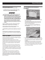
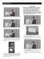
To properly open the roof, press down on the center top lip and release
the latch. If pressure is not applied from the top, the roof may appear
stuck. Always verify that the side lock is unlocked before attempting to lift
the roof.
BEFORE YOU BEGIN
Contact the local inspector or City Hall to be aware of all federal,
state and local codes that could impact the installation. Secure all
required permits before starting the job.
Carefully read and follow all of the procedures and safety
precautions detailed in the installation guide. If any portion of the
installation manual, technical manual or other factory-supplied
documents is not completely understood, contact a dealer for
assistance.
Fully comply with all relevant NEC, NFPA and OSHA standards
as well as all federal, state and local building and electric codes.
As with any generator, this unit must be installed in accordance
with current NFPA 37 and NFPA 70 standards as well as any other
federal, state, and local codes for minimum distances from other
structures.
Every installation has its own unique set of circumstances
and requirements. This booklet provides guidelines for basic
installations only and is not intended to cover all applications.
If there are any questions or concerns after carefully reading all
documentation received with the equipment, contact the nearest
dealer for assistance.
SITE PREPARATION AND GENERATOR
PLACEMENT
1. Locate the mounting area as close as possible to the transfer
switch and fuel supply.
Leave adequate room around the area for service access
(check local code), and place high enough to keep rising
water from reaching the generator.
Choose an open space that will provide adequate and
unobstructed airflow (see the “Location” section in the
Owner’s Manual).
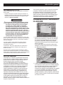
2. Place the unit so air vents won’t become clogged with leaves,
grass, snow or debris. Make sure exhaust fumes will not enter
the building through eaves, windows, ventilation fans or other
air intakes.
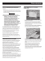
Dig a rectangular area approximately five inches deep and
about six inches longer and wider than the footprint of the
generator. Cover with polyurethane film and fill with pea gravel
or crushed stone. Compact and level the stone. A concrete
pad can be poured if desired.
General Information

4
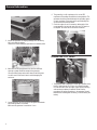
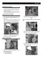
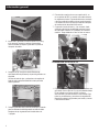
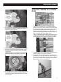
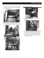
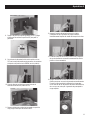
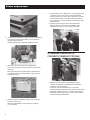
3. Inspect the generator for shipping damage and if necessary,
file a claim with the shipper.
Remove the bands holding the generator to the wooden pallet.
4. Make sure the lifting equipment to be used has sufficient
capacity to safely handle the weight of the generator.
Use nylon lifting straps and connect them to the lifting eyes
on each corner of the base frame to avoid damaging the
enclosure.
5. Set the generator onto the pad so that the gravel bed extends
beyond the generator on all sides.
Make sure the generator is level within ½ inch.
6. The ground lug is a UL requirement, it is not an NEC
requirement. Grounding should follow local regulations. The
generator should be grounded through the grounding (green
or bare) conductor to the main service ground through the
service disconnect transfer switch.
7. Check the engine oil and, if necessary, add enough of the
recommended oil to bring the level up to the FULL mark on
the dipstick. Be careful not to overfill the crankcase.
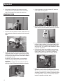
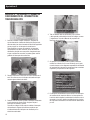
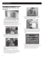
CONVERTING TO LP VAPOR
1. The generator was configured for natural gas operation at the
factory. Switching over to LP Vapor is a simple procedure.
On units with the 8 KVA unit engine, begin by disconnecting
and removing the battery if installed. Follow all of the
procedures and safety precautions in the generator Owner’s
Manual when installing and connecting, or disconnecting the
battery.
General Information

5
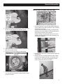
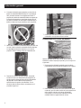
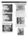
2. Open the roof, loosen the forward clamp on the air inlet hose,
and slide the hose away from the hose fitting (8 KVA).
3. Slide the fuel selector pin on the carburetor out towards the
back of the enclosure (8 KVA).
4. Replace the inlet hose and tighten the clamp securely.
5. On 10 and 13 KVA models, simply remove the air cleaner
cover and slide the fuel selector pin outward from the natural
gas to the LP position.
INSTALLING & CONNECTING GAS LINES
1. Both natural gas and LP Vapor are highly volatile substances,
so strict adherence to all safety procedures, codes, standards
and regulations is essential.
Gas line connections should be made by a certified plumber
familiar with local codes. Always use AGA-approved gas pipe
and a quality pipe sealant or joint compound.
Verify the capacity of the natural gas meter or the LP tank in
regards to providing sufficient fuel for both the generator and
other operating appliances.
2. Most applications will require an external manual shutoff valve
on the fuel line.
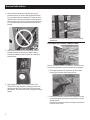
3. Where the gas line is to enter the generator, install a T-fitting
to allow for gas pressure monitoring. On one opening of the
fitting install a ¼” NPT nipple and threaded plug. In some
cases a sediment trap may also be installed.
General Information

6
4. When connecting the gas line to the generator, use the
provided section of UL Listed or AGA-approved flexible fuel
line in accordance with local regulations. The purpose of the
flexible fuel line is to ensure that vibration from the generator
does not cause a gas leak at one of the connection points, so
it’s important that the line be installed with as few bends as
possible.
5. Never bend the flexible fuel line to avoid using an elbow.
Bending the flexible line decreases its ability to absorb
vibrations and defeats its purpose as well as constricts the
actual fuel flow.
6. After checking for leaks, check the gas pressure at the
REGULATOR to make sure there’s enough gas pressure for
generator operation. See Owner’s Manual for fuel pressure
specifications. If not within these limits, contact your local gas
supplier.
7. When finished checking the gas pressure, close the manual
shutoff valve.
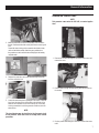
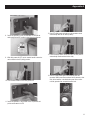
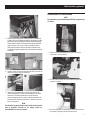
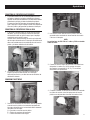
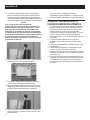
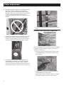
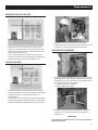
EXTERNAL ELECTRICAL CONNECTIONS
Some of the materials shown in the installation instructions must
be purchased separately and are not included with the generator.
1. Drill an appropriate size hole, and feed the pre-wired conduit
running from the transfer switch through the hole.
2. Remove the knockout in the back of the connection box, feed
the wires through the back of the box and secure the conduit
with the lock nut.
Seal the hole with silicone caulk. Don’t forget to caulk the hole
inside the house as well.
General Information

7
3. Mount the connection box so that it completely covers the hole in
the wall. Caulk around the sides and top of the box to ensure a good
seal.
Connect all wires to the lugs in the connection box (black to black,
red to red and white to white). Attach the green ground wire to
the ground screw and connect the two small plugs to their mating
receptacle ends.
4. Replace the protective cover plate and retaining screw, and
lock the connection box.
5. Locate the metal hasp that is packaged in the owner’s manual
bag. Insert the hasp in the slot located on the left side of the
external circuit breaker box. Be sure that the clip of the hasp
is facing toward the front of the generator. If desired, lock the
external box.
NOTE:
This circuit breaker may be classified as the disconnect circuit
for the generator. Check local codes for locking and/or lockout
procedures.
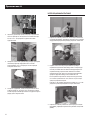
GENERATOR CONNECTIONS
NOTE:
This generator comes wired for 220 VAC, no neutral applica-
tions.
1. Remove the screws securing the connection area cover, and
remove the cover.
2. Feed the wires through the back of the generator and secure
the conduit.
3. Run the power leads through a cable tie or some other strain
relief.
General Information

8
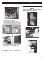
4. The circuit breaker is attached to the exterior access panel.
5. Remove the plastic plugs inside the main breaker access area
to allow connection of the power leads to the circuit breaker.
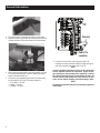
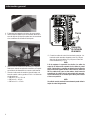
6. Now connect the power leads to the circuit breaker. Since this
is a single-phase application, it doesn’t matter which power
lead is connected to which lug.
7. Connect the green equipment ground wire to the ground bus
bar and torque to 35 inch lbs. The torque values are:
• 10-14 AWG = 35 in/lbs
• 8 AWG = 40 in/lbs
• 4-6 AWG = 45 in/lbs
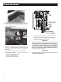
T1
N2
N1
209
210
0
194
23
GND
T2
Ground
Cable Tie
Location
8. Connect the control wires to the correct terminals. The
terminals are clearly marked N1 and N2 for utility sensing; 23
and 194 for transfer relay control; and T1 and T2.
NOTE:
In order to maintain separation of circuits, the DC control wires
must be separated from the AC control wires. A piece of fiber-
glass sleeving has been provided in the manual kit to achieve
this. Slide the sleeving over the AC wires OR the DC wires, but
not both, from the wire landing area to the outside of the gen-
erator. Use the cable tie locations to hold the sleeving in place.
NOTE:
An improperly connected control wire can damage the generator
control board.
General Information

9
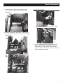
9. Inside the generator, locate the connection panel behind
the control panel. Remove the cover to expose customer
connections.
10. Connect a non-supplied T2 wire from the T2 fuse located in
the transfer switch to the post in the left rear of the connection
panel as shown.
BATTERY INSTALLATION
1. A group 26R battery is recommended for these generators.
2. Follow all of the procedures and safety precautions in the
generator Owner’s Manual when installing the battery.
Verify the switch is in the off position. When preparing for
operational testing, DO NOT connect the battery until transfer
switch connections are complete.
General Information

10
APPENDIX A – RTSI TRANSFER SWITCH
INSTALLATION & OPERATIONAL TESTING
1. Before beginning any installation, make sure power is shut
OFF to the main distribution panel and carefully read the
Owner’s Manual that came with the transfer switch.
To simplify the installation process, the transfer switch
should be mounted as close to the main distribution panel as
possible. Make sure no water or corrosive substances can
drip onto the transfer switch enclosure.
2. Always inspect the switch for shipping damage. Never mount
a transfer switch that shows any evidence of damage.
3. Protect against impact and mount the switch vertically to a rigid
support structure. Make sure the switch is level and plumb.
Check local codes before wiring the transfer switch. Some
jurisdictions require that wiring inside the switch be done by a
licensed electrician.
4. All wiring must be the correct size and type, and must
conform to all codes, standards and regulations. Refer to the
transfer switch Owner’s Manual.
5. As with any product, design changes can occur over time, so
always refer to the schematics in the transfer switch Owner’s
Manual for the required connections and safety precautions.
6. The transfer switch being used is an open transition switch.
Open transition switches prevent electrical feedback between
the generator and the utility by only allowing load circuits to
be connected to one power supply at a time.
Appendix A

11
SELECTED CIRCUIT COVERAGE
1. The generator powers only designated circuits that are grouped
together and wired into a separate priority distribution panel.
The transfer switch is installed between the main distribution
panel and the priority panel.
The amperage rating of the transfer switch must be equal to
or greater than the highest amperage rating of the utility and
generator breakers feeding the switch.
WHOLE-HOUSE CIRCUIT COVERAGE
1. The generator will be backing up all electrical loads within the
panel, so the amperage rating of the transfer switch must be
equal to or greater than the amperage rating of the normal
utility service.
A main service disconnect must be located before the transfer
switch. The transfer switch must be installed between the
utility service entrance and the building distribution panel.
2. The grounding that is normally in the main panel must be
accomplished in the service rated switch and must be
disconnected in the existing distribution panel.
ELECTRICAL CONNECTIONS
1. Connect the power leads from both the generator and the
utility to the appropriate lugs in the transfer switch. The lugs
are clearly marked in the switch.
N = Normal Utility Supply
E = Generator Connection Panel
T = Load Distribution Panel
2. Neutral wires from both the utility and the generator are
connected to the same neutral lug in the switch.
NOTE:
220VAC 2-Wire 50Hz applications will not have the Neutral
wires.
3.
Connect the control wires from the generator to the designated
locations. Wires 23 and 194 connect to the terminal strip; N1,
N2, T1 and T2 connect directly to the fuse holders.
4. Complete the transfer switch wiring by connecting the
equipment ground wires from both the utility and the
generator to the ground lug.
Appendix A

12
5. Being careful to support the lugs, torque the lugs in the
transfer switch to the specifications shown on the transfer
switch. Decal located on the inside of the switch door.
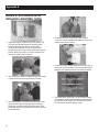
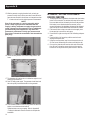
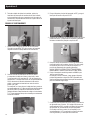
OPERATIONAL TESTING
1. Switch the main utility breaker OFF. Refer to NFPA 70-E for the
safety equipment required when working inside a live transfer
switch.
2. Energize the utility and check line-to-line and line-to-neutral
(if applicable) voltage at terminals N1 and N2 on the transfer
contactor. If line-to-line voltage is not approximately 220 volts,
de-energize utility power and check the terminations between
the utility and N1 and N2.
If applicable, if line-to-neutral voltage is not approximately
110 volts, de-energize utility power and check the neutral
terminations.
Repeat the same voltage checks on terminals T1 and T2 to
make sure current is flowing properly through the contactor.
3. Switch the generator’s main circuit breaker OFF and put the
mode switch in the OFF position.
4. Make sure utility power is OFF and place all of the individual
circuit
breakers in the main distribution panel in the OFF position.
5. Locate the transfer handle, insert the metal end into the slot in
the main contactor assembly. Pull the handle DOWN to move
the main contacts to the standby power (generator) position.
NEVER OPERATE THE TRANSFER SWITCH MANUALLY WHEN
LOADS ARE CONNECTED.
6. Put the generator’s mode switch in MANUAL to start the engine.
Allow the engine to warm up, then switch the generator’s main
breaker to the ON position. The generator is now supplying
electricity to the transfer switch but is not carrying any load.
7. Check to be sure that voltage and frequency from the
generator is correct. If line-to-
line voltage is not approximately
220 volts, refer to the generator
Owner’s Manual for the proper
adjustment procedures. If line-to-neutral (if applicable) voltage
is not approximately 110 volts, check the neutral connection
between the generator and transfer switch.
Appendix A

13
8. Switch the generator’s main circuit breaker OFF and put the
mode switch in the OFF position to shut down the generator.
9. With utility power still OFF, use the transfer handle to move the
main contacts to the UP (utility) position.
10. Close the main breaker to turn utility power ON.
11. Switch the generator’s main breaker to the ON position and
put the mode switch in AUTO.
12. Shut OFF utility power and make sure the generator starts
automatically after the line interrupt delay.
13. Switch the utility breaker to ON and make sure that power is
automatically transferred back to the utility.
14. Shut OFF utility power again to automatically start the
generator. When power has transferred to the generator, close
each of the breakers in the distribution panel one at a time
until the generator has accepted the entire load.
Appendix A

14
15. With the generator carrying the entire load, recheck gas
pressure to verify that it’s at the same level it was before the
generator was started. It should have not changed more than
1” of water column from the original pressure measurement.
NOTE:
Even if the generator is running smoothly at this
point, a drop in gas pressure indicates that the
supply is barely adequate to supply the generator’s
needs. Changes in the generator load, or additional
gas demand by other appliances may affect the
generator’s performance. Verify gas pressure and
pipe sizing. Unhook the manometer and reinstall the
port plug.
16. Switch the utility breaker ON to restore utility power to the
home.
17. The generator will continue to run to allow the engine to cool
down, then shut itself off.
18. Shut OFF utility power again. The generator should start and
the entire priority load should transfer to the generator.
19. Close the main breaker to restore utility power and allow the
engine to cool down and shut itself off.
Operational tests are now complete. Refer to Appendix B
– Setting the Automatic Exercise Function to complete the
installation.
APPENDIX B - SETTING THE AUTOMATIC
EXERCISE FUNCTION
1. The display will enter an Installation Assistant mode when battery
power is first connected. The assistant will prompt to first enter
the current date and time, followed by the exercise day and time.
If the battery is ever disconnected and reconnected, or fuse
removed and replaced, the Installation Assistant will be displayed
again, but only the current date and time will need to be entered.
2. If the exercise time or day ever needs to be changed, press
the escape key to access the main menu.
3. Press the left or right arrow key until ‘Edit’ is flashing and press
enter.
4. Press the right or left arrow key until the exercise time is
displayed and press enter.
5. Using the arrow and enter keys first set the exercise hour in
24 hour format, followed by the minute, and finally the day.
6. Once set, the generator will exercise each week at the same
time. Be sure to show the owners how to set the exercise
function for the day and time they want the unit to exercise.
Appendix B

15
Notes

16
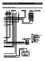
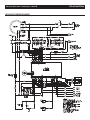
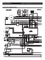
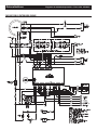
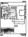
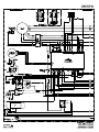
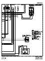
Electrical Data Wiring Diagram/Schematic - Drawing No. 0J2090-C
FOR USE WITH CONTROLLER 0H6680B

17
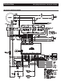
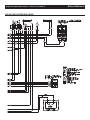
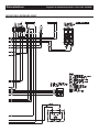
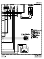
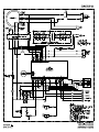
Electrical Schematic - Drawing No. 0J2090-C Electrical Data
FOR USE WITH CONTROLLER 0H6680B

18
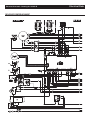
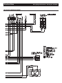
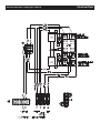
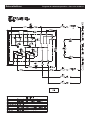
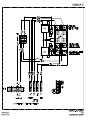
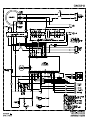
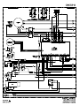
Electrical Data Wiring Diagram/Schematic - Drawing No. 0J2090-C
FOR USE WITH CONTROLLER 0H6680B
Страница загружается ...
Страница загружается ...
Страница загружается ...
Страница загружается ...
Страница загружается ...
Страница загружается ...
Страница загружается ...
Страница загружается ...
Страница загружается ...
Страница загружается ...
Страница загружается ...
Страница загружается ...
Страница загружается ...
Страница загружается ...
Страница загружается ...
Страница загружается ...
Страница загружается ...
Страница загружается ...
Страница загружается ...
Страница загружается ...
Страница загружается ...
Страница загружается ...
Страница загружается ...
Страница загружается ...
Страница загружается ...
Страница загружается ...
Страница загружается ...
Страница загружается ...
Страница загружается ...
Страница загружается ...
Страница загружается ...
Страница загружается ...
Страница загружается ...
Страница загружается ...
Страница загружается ...
Страница загружается ...
Страница загружается ...
Страница загружается ...
Страница загружается ...
Страница загружается ...
Страница загружается ...
Страница загружается ...
Страница загружается ...
Страница загружается ...
Страница загружается ...
Страница загружается ...
Страница загружается ...
Страница загружается ...
Страница загружается ...
Страница загружается ...
Страница загружается ...
Страница загружается ...
Страница загружается ...
Страница загружается ...
Страница загружается ...
Страница загружается ...
Страница загружается ...
Страница загружается ...
-
 1
1
-
 2
2
-
 3
3
-
 4
4
-
 5
5
-
 6
6
-
 7
7
-
 8
8
-
 9
9
-
 10
10
-
 11
11
-
 12
12
-
 13
13
-
 14
14
-
 15
15
-
 16
16
-
 17
17
-
 18
18
-
 19
19
-
 20
20
-
 21
21
-
 22
22
-
 23
23
-
 24
24
-
 25
25
-
 26
26
-
 27
27
-
 28
28
-
 29
29
-
 30
30
-
 31
31
-
 32
32
-
 33
33
-
 34
34
-
 35
35
-
 36
36
-
 37
37
-
 38
38
-
 39
39
-
 40
40
-
 41
41
-
 42
42
-
 43
43
-
 44
44
-
 45
45
-
 46
46
-
 47
47
-
 48
48
-
 49
49
-
 50
50
-
 51
51
-
 52
52
-
 53
53
-
 54
54
-
 55
55
-
 56
56
-
 57
57
-
 58
58
-
 59
59
-
 60
60
-
 61
61
-
 62
62
-
 63
63
-
 64
64
-
 65
65
-
 66
66
-
 67
67
-
 68
68
-
 69
69
-
 70
70
-
 71
71
-
 72
72
-
 73
73
-
 74
74
-
 75
75
-
 76
76
-
 77
77
-
 78
78


Generac 8 kVA 0059140 Руководство пользователя
- Категория
- Генераторы
- Тип
- Руководство пользователя
Задайте вопрос, и я найду ответ в документе
Поиск информации в документе стал проще с помощью ИИ
на других языках
- English: Generac 8 kVA 0059140 User manual
- español: Generac 8 kVA 0059140 Manual de usuario