Indesit KN1G21(W)/UA Руководство пользователя
- Категория
- Кухонные плиты (варочные панели)
- Тип
- Руководство пользователя
Это руководство также подходит для

English
Русский
Украінська
GB
RS
UA
Operating Instructions
COOKER AND OVEN
Contents
Operating Instructions,1
Description of the appliance-Overall view,2
Description of the appliance-Control Panel,3
Installation,4
Start-up and use,8
Precautions and tips,11
Care and maintenance,12
Assistance,12
Руководство по эксплуатации
КУХОННАЯ ПЛИТА С ДУХОВЫМ ШКАФОМ
Содержание
Руководство по эксплуатации,1
Описание изделия-Общий вид,2
Описание изделия-Панель управления,3
Монтаж,13
Включение и эксплуатация,18
Предосторожности и рекомендации,21
Техническое обслуживание и уход,22
Техническое обслуживание,22
Інструкціі з експлуатаціі
КУХНЯ
Зміст
Інструкціі з експлуатаціі,1
Опис установки-Загальнии вигляд,2
Опис установки-Панель управління,3
Встановлення,23
Включення і використання,27
Запобіжні засоби і поради,30
Догляд i технічне обслуговування,31
Допомога,31
LV
Latviešu
Lietoрanas instrukcija
PLОTS UN KRASNS
Saturs
Lietoрanas instrukcija,1
Ierоces apraksts -Vispвrоga informвcija,2
Ierоces apraksts - Vadоbas panelis,3
Uzstвdорana,41
eslзgрana un lietoрana,45
Piesardzоbas pasвkumi un ieteikum,48
Tehniskв apkope un kopрana,49
Palоdzоba,49
EE
Eesti keeles
Kasutusjuhend
PLIIT JA AHI
Sisukord
Kasutusjuhend,1
Seadme kirjeldus - Ülevaade,2
Seadme kirjeldus - Juhtpaneel,3
Paigaldamine,50
Esmakäitamine ja kasutamine, 54
Ettevaatusabinőud ja soovitused, 57
Hooldus,58
Klienditugi,58
KN1G21/UA
KN1G21S/UA
EnglishEnglish
Руководство по эксплуатации
КУХОННАЯ ПЛИТА С ДУХОВЫМ ШКАФОМ
Содержание
Руководство по эксплуатации
КУХОННАЯ ПЛИТА С ДУХОВЫМ ШКАФОМ
Содержание
РусскийРусский
Інструкціі з експлуатаціі
КУХНЯ
Зміст
Інструкціі з експлуатаціі
КУХНЯ
Зміст
УкраінськаУкраінська
Kasutusjuhend
PLIIT JA AHI
Sisukord
Kasutusjuhend
PLIIT JA AHI
Sisukord
Lietoрanas instrukcija
PLОTS UN KRASNS
Saturs
Lietoрanas instrukcija
PLОTS UN KRASNS
Saturs
Latviešu
KZ
Ɉɪɧɚɬɭ
Ԕԝɪɵɥԑɵɫɢɩɚɬɬɚɦɚɫɵ
ɀɚɥɩɵ ɲɨɥɭ
Ȼɚɫԕɚɪɭ ɬɚԕɬɚɫɵ
ɉɚɣɞɚɥɚɧɭɧԝɫԕɚɭɥɵԑɵ
Ԕԝɪɵɥԑɵɫɢɩɚɬɬɚɦɚɫɵ
Ԕɨɫɭɠԥɧɟɩɚɣɞɚɥɚɧɭ
ɋɚԕɬɚɧɞɵɪɭɥɚɪ
ɦɟɧɤɟԙɟɫɬɟɪ
Ʉԛɬɿɦɠԥɧɟɬɟɯɧɢɤɚɥɵԕ
ԕɵɡɦɟɬɤԧɪɫɟɬɭ
Ʉԧɦɟɤ
ɉɚɣɞɚɥɚɧɭɧԝɫԕɚɭɥɵԑɵ
ɉɅɂɌȺ
Ɇɚɡɦԝɧɵ
Ԕɚɡɚԕɲɚ
1
2
3
59
63
66
67
67
Ԕɚɡɚԕɲɚ
LT
Lietuviu
Naudojimo instrukcijos
viryklë ir orkaitë
Turinys
Naudojimo instrukcijos,1
Prietaiso aprašymas -Bendras vaizdas,2
Prietaiso aprašymas -Valdymo pultas,3
Montavimas,32
Ájungimas ir naudojimas,36
Orkaitës naudojimas,30
Atsargumo priemonës ir patarimai,39
Techninë prieţiűra,40
Pagalba,40
Turinys
Lietuviu
Naudojimo instrukcijos
viryklë ir orkaitë

2
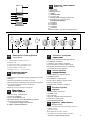
1.Hob burner
2.Hob Grid
3.Control panel
4.Sliding grill rack
5.DRIPPING pan
6.Adjustable foot
7.Containment surface for spills
8.GUIDE RAILS for the sliding racks
9.position 5
10.position 4
11.position 3
12.position 2
13.position 1
14. Glass Cover *(Available only on certain
models)
Description of the appliance
Overall view
GB
1 Газовые горелки
2 Рабочая поверхность
3 Панель управления
4 Решетка духовки
5 Противень или жарочный лист
6 Регулируемые ножки
7Электрические конфорки
8
HAПPABЛЯЮЩИE для противеней решеток
9 Положение 1
10 Положение 2
11 Положение 3
12 Положение 4
13 Положение 5
14
Cтеклянная крышка*
(
Имеется только в некоторых моделях.)
Описание изделия
Общий вид
UA
Опис плити
Загальнии вигляд
1. Газовий пальник
2. Піддон на випадок переливань
3.Панель управління
4.Полка РЕШІТKИ
5.Полка ДEКО
6.Лапка для налаштування
7.Пoверхня для збирання збiглoї piдини
8.HAПPABЛЯЮЧІ для полиць
9.положення 5
10.положення 4
11.положення 3
12.положення 2
13.положення 1
14. Скляна кришка *(Є лише в деяких моделях.)
RS
1 Dujų degiklis
2 Kaitlentès tinklelis
3 Valdymo pultas
4 KEPSNINÈ
5 SURINKIMO INDAS
6 Reguliuojamoji kojelè
7 TIškalų sulaikymo paviršius
8 Slankiųjų grotelių TAKELIAI
9 padètis 5
1 padètis 4
11padètis 3
12 padètis 2
13 padètis 1
14 Stiklinis gaubtas *(Yra tik tam tikruose modeliuose)
Prietaiso aprađymas
Bendras vaizdas
LT
1 Gćzes deglis
2 Plīts virsmas režģisģ
3 Vadības panelis
4 GRILĒŠANA
5 CEPE TAUKU PANNA
6 Regulējama kāja
7 Norobe˛ota virsma traipiem
8 VADOTNES slīdošo pamatņu ievietošanai un izņemšanai
9 pozīcija 5
10 pozīcija 4
11 pozīcija 3
12 pozīcija 2
13 pozīcija 1
14 Stikla pārsegs* (Pieejams tikai noteiktiem modeļiem)
Ierîces apraksts
Vispariga informacija
LV
1 Gaasipõleti
2 Rest
3 Juhtpaneel
4 GRILL
5 TILGAPANN
6 Reguleerimisjalg
7 Tilgaalus
8 SIINID restide sisestamiseks
9 tasand 5
10 tasand 4
11 tasand 3
12 tasand 2
13 tasand 1
14 Klaaskate *(Ainult mőnedel mudelitel)
Seadme kirjeldus
Ülevaade
EE
1
2
3
4
5
6
6
7
8
9
10
11
12
13
14

3
Description of the appliance
Control panel
GB
1.GAS BURNER IGNITION button*
2.TIMER knob*
3.OVEN AND GRILL CONTROL knob
4.OVEN LIGHT / ROTISSERIE button*
5.Hob BURNER control knob
*Available only on certain models
Описание изделия
Панель управления
UA
Опис плити
Панель управління
RS
1.Электронное зажигание конфорок варочной панели*
2.Таймер*
3.Рукоятка управления духовкой и грилем
4.Кнопка включения/выключения освещения духовки *
5. Рукоятки включения газовых конфорок
варочной панели
*Имеется только в некоторых моделях.
1. Автоматичне запалювання*
2.Сукоятка ТАЙМЕРА*
3. Ручка ДУХОВКА й гриля
4.КНОПКА РОЖНА та ОСВІТЛЕННЯ ДУХОВКИ*
5.Ручки для керування газовими
пальниками на варильній поверхні
*
Є лише в деяких моделях
Ierîces apraksts
Vispariga informacija
LV
1.GĀZES DEGĻA iedegšanas poga*
2.TAIMERA slēdzis*
3.Cepeškrāsns un grila slēdzis
4.Poga krāsns vieglās un spļaut cepetis*
5.DEGĻA vadības slēdzi
*Pieejams tikai noteiktiem modeļiem
Prietaiso aprađymas
Valdymo pultas
LT
1.Elektroninis kaitlentčs degikilř apšvietimas*
2.LAIKMAČIO rankenčlč*
3. Orkaitë ir grilio valdymo rankenëlë
4.Krosnies šviesos ir iešmo kepta mygtuk*
5.Kaitlentčs dujř degikilř valdymo rankenčlčs
* Yra tik tam tikruose modeliuose
Seadme kirjeldus
Juhtpaneel
EE
1.GAASIPÕLETI süütenupp*
2.TAIMERI nupp*
3.Ahju juhtnupp
4.Ahju tuli / sülitada röstitud süütenupp*
5.PÕLETITE reguleernupp
*
Ainult mőnedel mudelitel
1
5
3
4
2
KZ
1
2.
7.
3.
4.
5.
6.
8.
9.
10.
11.
12.
13.
14.
ɀɚɥɩɵɲɨɥɭ
Құрылғы
сипаттамасы
Газ оттығы
Плита торы
Төгілген сұйықтықтарды ұстайтын
бет
Басқару тақтасы
ГРИЛЬ
ТҰТҚАЛЫ ТАБА
Реттелетін аяқ
Сырғымалы тартпаларға арналған
БАҒЫТТАУШЫ ЖОЛДАР
5-позиция
4-позиция
3-позиция
2-позиция
1-позиция
Шыны қақпақ
(Тек белгілі үлгілерде болады).
1
2
3
4
5
6
6
7
8
9
10
11
12
13
14
KZ
1.
2.
3.
4.
5.
Плита оттықтарына арналған электрондық тұтатқыш
Таймер тұтқасы
Пеш пен
грильді
Пеш шамы мен гриль-бар
түймесі
Плитадағы газ оттықтарын
басқару тұтқалары
Құрылғы
сипаттамасы
Басқару тақтасы
*
*
* Тек белгілі модельдерде болады
Опис плити
Панель управління
Опис плити
Панель управління
Панель управления
Описание изделия
Juhtpaneel
Valdymo pultasValdymo pultas
Vispariga informacijaVispariga informacija

4
GB
! Before operating your new appliance please read
this instruction booklet carefully. It contains important
information concerning the safe installation and
operation of the appliance.
! Please keep these operating instructions for future
reference. Make sure that the instructions are kept with
the appliance if it is sold, given away or moved.
! The appliance must be installed by a qualified
professional according to the instructions provided.
! Any necessary adjustment or maintenance must be
performed after the cooker has been disconnected
from the electricity supply.
! We recommend cleaning the oven before using it for
the first time, following the instructions provided in the
„Care and maintenance” section.
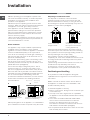
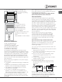
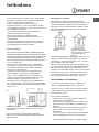
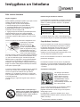
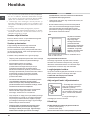
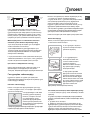
Room ventilation
The appliance may only be installed in permanently-
ventilated rooms, according to current national
legislation. The room in which the appliance is installed
must be ventilated adequately so as to provide as
much air as is needed by the normal gas combustion
process (the flow of air must not be lower than 2 m
3
/h
per kW of installed power).
The air inlets, protected by grilles, should have a duct
with an inner cross section of at least 100 cm
2
and
should be positioned so that they are not liable to even
partial obstruction (see gure A).
These inlets should be enlarged by 100% - with a
minimum of 200 cm
2
- whenever the surface of the
hob is not equipped with a flame failure safety device.
When the flow of air is provided in an indirect manner
from adjacent rooms (see gure B), provided that these
are not communal parts of a building, areas with
increased fire hazards or bedrooms, the inlets should
be fitted with a ventilation duct leading outside as
described above.
A B
! After prolonged use of the appliance, it is advisable to
open a window or increase the speed of any fans used.
Disposing of combustion fumes
The disposal of combustion fumes should be
guaranteed using a hood connected to a safe and
efficient natural suction chimney, or using an electric
fan that begins to operate automatically every time the
appliance is switched on (see gure).
! The liquefied petroleum gases are heavier than air
and collect by the floor, therefore all rooms containing
LPG cylinders must have openings leading outside so
that any leaked gas can escape easily.
LPG cylinders, therefore, whether partially or
completely full, must not be installed or stored in rooms
or storage areas that are below ground level (cellars,
etc.). Only the
cylinder being used should be stored in the room; this
should also be kept well away from sources
of heat (ovens, chimneys, stoves) that may cause
the temperature of the cylinder to rise above 50°C.
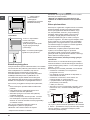
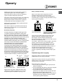
Positioning and levelling
! It is possible to install the appliance alongside
cupboards whose height does not exceed that of the
hob surface.
! Make sure that the wall in contact with the back of
the appliance is made from a non-flammable, heat-
resistant material (T 90°C).
To install the appliance correctly:
• Place it in the kitchen, dining room or the bed-sit (not
in the bathroom).
• If the top of the hob is higher than the cupboards,
the appliance must be installed at least 200 mm away
from them.
• If the cooker is installed underneath a wall cabinet,
there must be a minimum distance of 420 mm
between this cabinet and the top of the hob.
This distance should be increased to 700 mm if the
wall cabinets are flammable (see gure).
• Do not position blinds behind the cooker or less than
200 mm away from its sides.
A
Fumes channelled through
a chimney or branched
flue system reserved for
cooking appliances)
Installation
Adjacent room Room requiring
ventilation
Ventilation opening for
comburent air
Increase in the gap between
the door and the flooring
Fumes channelled
straight outside

5
GB
• Any hoods must be installed according to the
instructions listed in
the relevant operating
manual.
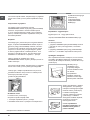
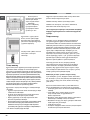
Levelling
If it is necessary to level
the appliance, screw the
adjustable feet into the
places provided on each
corner of the base of the
cooker (see gure).
The legs* fit into the slots on the
underside of the base of the
cooker.
Electrical connection
an omnipolar circuit-breaker with a minimum contact
opening of 3 mm installed between the appliance and the
mains. The circuit-breaker must be suitable for the charge
indicated and must comply with NFC 15-100 regulations
(the earthing wire must not be interrupted by the circuit-
breaker). The supply cable must be positioned so that it
does not come into contact with temperatures higher than
50°C at any point.
Before connecting the appliance to the power supply,
make sure that:
• The appliance is earthed and the plug is compliant with
the law.
• The socket can withstand the maximum power of the
appliance, which is indicated by the data plate.
• The voltage is in the range between the values
indicated on the data plate.
• The socket is compatible with the plug of the
appliance. If the socket is incompatible with the
plug, ask an authorised technician to replace it. Do
not use extension cords or multiple sockets.
! Once the appliance has been installed, the power
supply cable and the electrical socket must be easily
accessible.
HOOD
420
Min.
min.
650
mm. with hood
min.
700
mm. without hood
mm.
600
Min. mm.
420
Min. mm.
* Only available in certain models
! The cable must not be bent or compressed.
! The cable must be checked regularly and replaced
by authorised technicians only.
! The manufacturer declines any liability should
these safety measures not be observed.
Gas connection
Connection to the gas network or to the gas cylinder
may be carried out using a flexible rubber or steel hose,
in accordance with current national legislation and after
making sure that the appliance is suited to the type of gas
with which it will be supplied (see the rating sticker on
the cover: if this is not the case see below). When using
liquid gas from a cylinder, install a pressure regulator
which complies with current national regulations. To
make connection easier, the gas supply may be turned
sideways*: reverse the position of the hose holder with
that of the cap and replace the gasket that is supplied
with the appliance.
! Check that the pressure of the gas supply is
consistent with the values indicated in the Table
of burner and nozzle specifications (see below).
This will ensure the safe operation and durability of
your appliance while maintaining efficient energy
consumption.
Gas connection using a flexible rubber hose
Make sure that the hose complies with current national
legislation. The internal diameter of the hose must
measure: 8 mm for liquid gas supply; 13 mm for
methane gas supply.
Once the connection has been performed, make sure
that the hose:
• Does not come into contact with any parts that reach
temperatures of over 50°C.
• Is not subject to any pulling or twisting forces and
that it is not kinked or bent.
• Does not come into contact with blades, sharp
corners or moving parts and that it is not
compressed.
• Is easy to inspect along its whole length so that its
condition may be checked.
• Is shorter than 1500 mm.
• Fits firmly into place at both ends, where it will
be fixed using clamps that comply with current
regulations.
! If one or more of these conditions is not fulfilled
or if the cooker must be installed according to the
conditions listed for class 2 - subclass 1 appliances
(installed between two cupboards), the flexible steel
Install a standardised plug
corresponding to the load
indicated on the appliance data
plate (see Technical data table).
The appliance must be directly
connected to the mains using
hose must be used instead (see below).

6
GB
A
V
Connecting a flexible jointless stainless steel pipe to
a threaded attachment
Make sure that the hose and gaskets comply with
current national legislation.
To begin using the hose, remove the hose holder on the
appliance (the gas supply inlet on the appliance is a
cylindrical threaded 1/2 gas male attachment).
! Perform the connection in such a way that the hose
length does not exceed a maximum of 2 metres,
making sure that the hose is not compressed and does
not come into contact with moving parts.
Checking the connection for leaks
When the installation process is complete, check the
hose fittings for leaks using a soapy solution. Never
use a flame.
Adapting to different types of gas
It is possible to adapt the appliance to a type of gas
other than the default type (this is indicated on the
rating label on the cover).
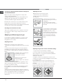
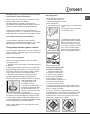
Adapting the hob
Replacing the nozzles for the hob burners:
1. Remove the hob grids and slide the burners off their
seats.
2. Unscrew the nozzles using a 7 mm socket spanner
(see gure), and replace them with nozzles suited to
the new type of gas(see Burner and nozzle speci cations
table).
3. Replace all the components
by following the above
instructions in reverse.
Adjusting the hob burners’
minimum setting:
1. Turn the tap to the minimum
position.
2. Remove the knob and adjust the regulatory screw,
which is positioned inside or next to the tap pin, until
the flame is small but steady.
! If the appliance is connected to a liquid gas supply,
the regulatory screw must be fastened as tightly as
possible.
3. While the burner is alight, quickly change the position of
the knob from minimum to maximum and vice versa several
times, checking that the flame is not extinguished.
! The hob burners do not require primary air
adjustment.
Adapting the oven
Replacing the oven burner nozzle:
1. Remove the oven compartment.
2. Slide out the protection panel A
(see diagram).
3. Remove the oven burner
after unscrewing the screws V
(see gure).
The whole operation will be
made easier if the oven door is
removed.
4. Unscrew the nozzle using a
special nozzle socket spanner
(see gure) or with a 7 mm
socket spanner, and replace it
with a new nozzle that is suited
to the new type of gas (see
Burner and nozzle speci cations
table).
Adjusting the gas oven
burner’s minimum setting:
1. Light the burner (see Start-up
and Use).
2. Turn the knob to the minimum position (MIN)
after it has been in the maximum position (MAX) for
approximately 10 minutes.
3. Remove the knob.
4. Tighten or loosen the adjustment screws on the
outside of the thermostat pin (see gure) until the flame
is small but steady.
! If the appliance is connected to liquid gas, the
adjustment screw must be fastened as tightly as
possible.
5. Turn the knob from the MAX position to the MIN
position quickly or open and shut the oven door,
making sure that the burner is not extinguished.

7
GB
Adapting the grill
Replacing the grill burner nozzle:
1. Remove the oven burner after loosening screw V
(see gure).
2. Unscrew the grill burner
nozzle using a special nozzle
socket spanner (see gure) or
preferably with a 7 mm socket
spanner, and replace it with a
new nozzle that is suited to the
new type of gas (see Burner and
nozzle speci cations table).
! Be careful of the spark plug
wires and the thermocouple
tubes.
! The oven and grill burners do
not require primary air adjustment.
! After adjusting the appliance so it may be used with
a different type of gas, replace the old rating label with
a new one that corresponds to the new type of gas
(these labels are available from Authorised Technical
Assistance Centres).
! Should the gas pressure used be different (or vary
slightly) from the recommended pressure, a suitable
pressure regulator must be fitted to the inlet hose in
accordance with current national regulations relating to
“regulators for channelled gas”.
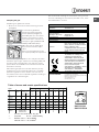
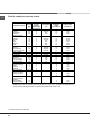
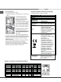
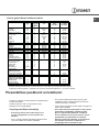
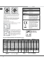
Table of burner and nozzle specifications
V
I
S
S
R
A
We recommend cleaning the oven before using it for the
first time, following the instructions provided in the „Care
and maintenance” section.
KN1G21/UA
KN1G21S/UA
TECHNICAL DATA
Oven dimensions
(HxWxD)
34x39x44 cm
Volume
58 l
Useful
measurements
relating to the oven
compartment
width 42 cm
depth 44 cm
height 18 cm
Power supply voltage
and frequency
see data plate
Burners
may be adapted for use with any
type of gas shown on the data
plate, which is located inside the
flap or, after the oven
compartment has been opened,
on the left-hand wall inside the
oven.
EC Directives: 2006/95/EC dated
12/12/06 (Low Voltage) and
subsequent amendments -
2004/108/EC dated 15/12/04
(Electromagnetic Compatibility)
and subsequent amendments -
2009/142/EC dated 30/11/09
(Gas) and subsequent
amendments - 93/68/EEC dated
22/07/93 and subsequent
amendments - 2002/96/EC.
1275/2008 (Stand-by/ Off mode)
Table 1 Liquid Gas Natural Gas
Burner Diameter
(mm)
Thermal Power
kW (p.c.s.*)
By-Pass
1/100
Nozzle
1/100
Flow*
g/h
Nozzle
1/100
Flow*
l/h
Nozzle
1/100
Flow*
l/h
Nominal Reduced (mm) (mm) *** ** (mm) (mm)
Fast
(Large)(R)
100 3.00 0.7 41 86 218 214 116 286 143 286
Semi Fast
(Medium)(S)
75 1.90 0.4 30 70 138 136 103 181 118 181
Auxiliary
(Small)(A)
55 1.00 0.4 30
50 73 71 79 95 80 95
Oven - 2.80 1.0 46 80 204 200 119 267 132 257
Grill - 2.30 - - 75 167 164 114 219 139 227
Supply
Pressures
Nominal (mbar)
Minimum (mbar)
Maximum (mbar)
28-30
20
35
37
25
45
20
17
25
13
6,5
18
* At 15°C and 1013 mbar- dry gas
** Propane P.C.S. = 50,37 MJ/Kg
*** Butane P.C.S. = 49,47 MJ/Kg
Natural P.C.S. = 37,78 MJ/m
3
ENERGY LABEL
and ECODESIGN
Regulation (EU) No 65/2014 supplemen-
ting Directive 2010/30/EU.
Regulation (EU) No 66/2014 implementing
Directive 2009/125/EC.
Standard EN 15181.
Standard EN 30-2-1

8
GB
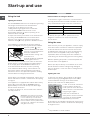
Using the hob
Lighting the burners
For each BURNER knob there is a complete ring showing
the strength of the flame for the relevant burner.
To light one of the burners on the hob:
1. Bring a flame or gas lighter close to the burner.
2. Press the BURNER knob and turn it in an
anticlockwise direction so that it is pointing to the
maximum flame setting E.
3. Adjust the intensity of the flame to the desired level
by turning the BURNER knob in an anticlockwise
direction. This may be the minimum setting C, the
maximum setting E or any position in between the two.
If the appliance is fitted with an electronic lighting
device* (see
gure
), press the ignition button, marked
with the symbol
, then
hold the BURNER knob down
and turn it in an anticlockwise
direction, towards the
maximum flame setting, until
the burner is lit.
Several models are equipped
with an ignition device
which is built into the knob; in this case the electronic
ignition device* is present (C) but the ignition button
is not. Simply press the BURNER knob and turn it
in an anticlockwise direction so that it is pointing
to the maximum flame setting, until the burner is lit.
The burner may be extinguished when the knob is
released. If this occurs, repeat the operation, holding
the knob down for a longer period of time.
! If the flame is accidentally extinguished, switch off the
burner and wait for at least 1 minute before attempting
to relight it.
If the appliance is equipped with a flame failure safety
device*(X), press and hold the BURNER knob for
approximately 2-3 seconds to keep the flame alight
and to activate the device.
To switch the burner off, turn the knob until it reaches
the stop position •.
Practical advice on using the burners
For the burners to work in the most
efficient way possible and to save
Start-up and use
on the amount of gas consumed, it is recommended
that only pans that have a lid and a flat base are used.
They should also be suited to the size of the burner.
To identify the type of burner, please refer to the
diagrams contained in the “Burner and nozzle
specifications”.
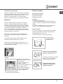
Using the oven
! The first time you use your appliance, heat the empty
oven with its door closed at its maximum temperature
for at least half an hour. Ensure that the room is well
ventilated before switching the oven off and opening
the oven door. The appliance may emit a slightly
unpleasant odour caused by protective substances
used during the manufacturing process burning away.
! Before operating the product, remove all plastic film
from the sides of the appliance.
! Never put objects directly on the bottom of the oven;
this will avoid the enamel coating being damaged.
Only use position 1 in the oven when cooking with the
rotisserie spit.
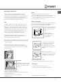
Lighting the oven
To light the oven burner, bring a flame or gas lighter
close to opening F (see gure) and press the OVEN
control knob while turning it in an anticlockwise
direction until it reaches the MAX position.
If, after 15 seconds, the burner
is still not alight, release the
knob, open the oven door and
wait for at least 1 minute before
trying to light it again.
! The oven is fitted with a
safety device and it is therefore
necessary to hold the OVEN
control knob down for approximately 6 seconds.
! If the flame is accidentally extinguished, switch off the
burner and wait for at least 1 minute before attempting
to relight the oven.
F
*
Only available in certain models.
X
C
WARNING! The glass lid can break
in if it is heated up. Turn off all the
burners and the electric plates before
closing the lid. *Applies to the models
with glass cover only.
Burner Cookware diameter (cm)
Fast (R) 24 - 26
Semi Fast (S) 16 - 20
Auxiliary (A) 10 - 14

9
GB
* Only available in certain models.
Adjusting the temperature
To set the desired cooking temperature, turn the
OVEN control knob in an anticlockwise direction.
Temperatures are displayed on the control panel and
may vary between MIN (140°C) and MAX (250°C).
Once the set temperature has been reached, the oven
will keep it constant by using its thermostat.
Grill
To light the grill, bring a flame or gas lighter close to
the burner and press the OVEN control knob while
turning it in a clockwise direction until it reaches the
d position. The grill enables the surface of food to be
browned evenly and is particularly suitable for roast
dishes, schnitzel and sausages. Place the rack in
position 4 or 5 and the dripping pan in position 1 to
collect fat and prevent the formation of smoke.
! The grill is fitted with a safety device and it is
therefore necessary to hold the OVEN control knob
down for approximately 6 seconds.
! If the flame is accidentally extinguished, switch off the
burner and wait for at least 1 minute before attempting
to relight the grill.
! When using the grill, leave the oven door ajar,
positioning the deflector D between the door and the
control panel (see gure) in order to prevent the knobs
from overheating.
Turnspit*
To operate the rotisserie (see
diagram) proceed as follows:
1. Place the dripping pan in
position 1.
2. Place the rotisserie support in
position 4 and insert the spit in the hole provided on the
back panel of the oven.
3. Acitvate the function
by pressing the
TURNSPIT button.
Oven light
The light may be
switched on at any
moment by pressing the
OVEN LIGHT button.
Timer*
To activate the Timer proceed as follows:
1. Turn the TIMER knob in a clockwise direction 4 for
almost one complete revolution to set the buzzer.
2. Turn the TIMER knob in an anticlockwise direction 5
to set the desired length of time.
Lower compartment*
There is a compartment underneath the oven that may
be used to store oven accessories or deep dishes. To
open the door pull it downwards (see gure).
! The internal surfaces of
the compartment (where
present) may become
hot.
! Do not place
flammable materials
in the lower oven
compartment.
D
A
S
In gas cooker models, there
is a sliding protection layer
A that shields the lower
compartment from the heat
generated by the burner (see
gure).
To remove the sliding
protection remove the screw S
(see gure). To replace it, lock
it in place with the screw S.
!Before using the oven make
sure that the sliding protection is fixed correctly.

10
GB
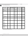
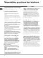
Oven cooking advice table
* Only available in certain models.
Food to be cooked
Wt.
(Kg)
Cooking position of
shelves from bottom
Temperature
(°C)
Pre-heating time (min)
Cooking time
(min.)
Pasta
Lasagne
Cannelloni
Pasta bakes au gratin
2.5
2.5
2.5
200-210
200
200
10
10
10
75-85
50-60
50-60
Meat
Veal
Chicken
Duck
Rabbit
Pork
Lamb
1.5
1.5
1.8
2.0
2.1
1.8
3
3
3
3
3
3
200-210
210-220
200
200
200
200
10
10
10
10
10
10
95-100
90-100
100-110
70-80
70-80
100-105
Fish
Mackerel
Dentex
Trout baked in paper
1.1
1.5
1.0
3
3
3
180-200
180-200
180-200
10
10
10
45-50
45-55
45-50
Pizza
Napolitan 1.0 4 210-220 15
20-25
Cake
Biscuits
Tarts
Savoury pie
Raised Cakes
0.5
1.1
1.0
1.0
4
4
4
4
180
180
180
170
15
15
15
15
25-35
40-45
50-55
40-45
Grill cooking
Veal steaks
Cutlets
Hamburgers
Mackerels
Toast sandwiches
1
1,5
1
1
n.° 4
4
4
4
3
4
4
5
5
5
5
5
15-20
20
20-30
15-20
4-5
Grill cooking with
rotisserie
Veal on the spit
Chicken on the spit
1
2
-
-
5
5
70-80
70-80
Grill cooking with multi-
skewer rotisserie (only a
few models)
Meat kebabs
Vegetable kebabs 1,0
0,8
-
-
5
5
40-45
25-30
NB: cooking times are approximate and may vary according to personal taste. When cooking using the grill, the dripping-pan must
always be placed on the 1st oven rack from the bottom.
4
4
4

11
GB
Precautions and tips
! This appliance has been designed and manufactured in
compliance with international safety standards.
The following warnings are provided for safety reasons and
must be read carefully.
General safety
• These instructions are only valid for the countries
whose symbols appear in the manual and on the serial
number plate.• The appliance was designed for domestic
use inside the home and is not intended for commercial or
industrial use.
• The appliance must not be installed outdoors, even in
covered areas. It is extremely dangerous to leave the
appliance exposed to rain and storms.
• Do not touch the appliance with bare feet or with wet or
damp hands and feet.
• The appliance must be used by adults only for
the preparation of food, in accordance with the
instructions outlined in this booklet. Any other
use of the appliance (e.g. for heating the room)
constitutes improper use and is dangerous.
The manufacturer may not be held liable for any
damage resulting from improper, incorrect and
unreasonable use of the appliance.
• The instruction booklet accompanies a class 1 (insulated)
or class 2 - subclass 1 (recessed between 2 cupboards)
appliance.
• Keep children away from the oven.
• Make sure that the power supply cables of other electrical
appliances do not come into contact with the hot parts of
the oven.
• The openings used for the ventilation and dispersion of
heat must never be covered.
• Do not close the glass hob cover (selected models only)
when the burners are alight or when they are still hot.
• Always use oven gloves when placing cookware in the
oven or when removing it.
• Do not use flammable liquids (alcohol, petrol, etc...) near
the appliance while it is in use.
• Do not place flammable material in the lower storage
compartment or in the oven itself. If the appliance is
switched on accidentally, it could catch fire.
• Always make sure the knobs are in the • position and that
the gas tap is closed when the appliance is not in use.
• When unplugging the appliance, always pull the plug from
the mains socket; do not pull on the cable.
• Never perform any cleaning or maintenance work without
having disconnected the appliance from the electricity
mains.
• If the appliance breaks down, under no circumstances
should you attempt to repair the appliance yourself.
Repairs carried out by inexperienced persons may cause
injury or further malfunctioning of the appliance. Contact
Assistance.
• Do not rest heavy objects on the open oven door.
• The appliance should not be operated by people
(including children) with reduced physical, sensory
or mental capacities, by inexperienced individuals
or by anyone who is not familiar with the product.
These individuals should, at the very least, be
supervised by someone who assumes responsibility
for their safety or receive preliminary instructions
relating to the operation of the appliance.
• Do not let children play with the appliance.
Disposal
• When disposing of packaging material: observe local
legislation so that the packaging may be reused.
• The European Directive 2002/96/EC relating to Waste
Electrical and Electronic Equipment (WEEE) states that
household appliances should not be disposed of using
the normal solid urban waste cycle. Exhausted appliances
should be collected separately in order to optimise
the cost of re-using and recycling the materials inside
the machine, while preventing potential damage to the
atmosphere and to public health. The crossed-out dustbin
is marked on all products to remind the owner of their
obligations regarding separated waste collection.
Exhausted appliances may be collected by the public
waste collection service, taken to suitable collection areas
in the area or, if permitted by current national legislation,
they may be returned to the dealers as part of an
exchange deal for a new equivalent product.
All major manufacturers of household appliances
participate in the creation and organisation of systems for
the collection and disposal of old and disused appliances.
Respecting and conserving the environment
• You can help to reduce the peak load of the electricity
supply network companies by using the oven in the hours
between late afternoon and the early hours of the morning.
• Check the door seals regularly and wipe them clean to
ensure they are free of debris so that they adhere properly
to the door, thus avoiding
heat dispersion.
• Whenever possible, avoid pre-heating the oven
and always try to fill it. Open the oven door as little
as possible because heat is lost every time it is
opened. To save a substantial amount of energy,
simply switch off the oven 5 to 10 minutes before the
end of your planned cooking time and use the heat
the oven continues to generate.
• Automatic programmes are based on standard food
product.
• Keep gaskets clean and tidy to prevent any door
energy losses
• If you have a timed tariff electricity contract, the “delay
cooking” option will make it easier to save money by
moving operation to cheaper time periods.

12
GB
Care and maintenance
Switching the appliance off
Disconnect your appliance from the electricity supply
before carrying out any work on it.
Cleaning the appliance
! Do not use abrasive or corrosive detergents such as
stain removers, anti-rust products, powder detergents
or sponges with abrasive surfaces: these may scratch
the surface beyond repair.
! Never use steam cleaners or pressure cleaners on
the appliance.
• It is usually sufficient simply to wash the hob using a
damp sponge and dry it with absorbent kitchen roll.
• The stainless steel or enamel-coated external parts
and the rubber seals may be cleaned using a
sponge that has been soaked in lukewarm water
and neutral soap. Use specialised products for the
removal of stubborn stains. After cleaning, rinse well
and dry thoroughly. Do not use abrasive powders or
corrosive substances.
• The hob grids, burner caps, flame spreader rings
and the hob burners can be removed
to make cleaning easier; wash them in hot water and
non-abrasive detergent, making sure all burnt-on
residue is removed before drying them thoroughly.
• For hobs with electronic ignition, the terminal part of
the electronic lighting devices should be cleaned
frequently and the gas outlet holes should be
checked for blockages.
• The inside of the oven should ideally be cleaned
after each use, while it is still lukewarm. Use hot
water and detergent, then rinse well and dry with a
soft cloth. Do not use abrasive products.
•
Clean the glass part of the oven door using a
sponge and a non-abrasive cleaning product, then
dry thoroughly with a soft cloth. Do not use rough
abrasive material or sharp metal scrapers as these
could scratch the surface and cause the glass to
crack.
• The accessories can be washed like everyday
crockery, and are even dishwasher safe.
• Stainless steel can be marked by hard water that
has been left on the surface for a long time, or by
aggressive detergents containing phosphorus.
After cleaning, rinse well and dry thoroughly. Any
remaining drops of water should also be dried.
The cover
If the cooker is fitted with
a glass cover, this cover
should be cleaned using
lukewarm water. Do not
use abrasive products.
It is possible to remove
the cover in order to make
cleaning the area behind
the hob easier. Open
the cover fully and pull it
upwards (see gure).
! Do not close the cover when the burners are alight or
when they are still hot.
Inspecting the oven seals
Check the door seals around the oven periodically. If
the seals are damaged, please contact your nearest
Authorised After-sales Service Centre. We recommend
that the oven is not used until the seals have been
replaced.
Gas tap maintenance
Over time, the taps may become jammed or difficult to
turn. If this occurs, the tap must be replaced.
! This procedure must be performed by a qualified
technician who has been authorised by the
manufacturer.
Replacing the oven
light bulb
1. After disconnecting the
oven from the electricity mains,
remove the glass lid covering
the lamp socket (see gure).
2. Remove the light bulb and
replace it with a similar one: voltage 230 V, wattage 25
W, cap E 14.
3. Replace the lid and reconnect the oven to the
electricity supply.
Assistance
Please have the following information handy:
• The appliance model (Mod.).
• The serial number (S/N).
This information can be found on the data plate located
on the appliance and/or on the packaging.
• The base of your pot or pan should cover the hot plate.
If it is smaller, precious energy will be wasted and
pots that boil over leave encrusted remains that can
be difficult to remove.
• Cook your food in closed pots or pans with well-fitting
lids and use as little water as possible. Cooking with
the lid off will greatly increase energy consumption
• Use purely flat pots and pans
• If you are cooking something that takes a long time,
it's worth using a pressure cooker, which is twice as
fast and saves a third of the energy.

13
RS
! Важно сохранить данное руководство для его
последующих консультации. В случае продажи,
передачи или переезда проверьте, чтобы данное
руководство сопровождало изделие.
! Внимательно прочитаите инструкции: в них
содержатся важные сведения об установке,
эксплуатации и безопасности изделия.
! Установка изделия производится в соответствии
с данными инструкциями квалифицированными
специалистами.
! Любая операция по
регуляции или техническому
обслуживанию должна производиться только
после отсоединения кухоннои плиты от сети
электропитания.
!Рекомендуем прочистить духовой шкаф перед
началом его эксплуатации, следуя инструкциям,
приведенным в параграфе «Обслуживание и уход».
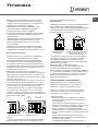
Вентиляция помещении
Изделие может быть установлено в помещениях
с постояннои вентиляциеи в соответствии с
деиствующими национальными нормативами. В
помещении, в котором
устанавливается изделие,
должен быть обеспечен приток воздуха в объеме,
необходимом для оптимального горения газа (расход
воздуха не должен быть меньше 2 м
3
/час на 1 кВт
установленнои мощности).
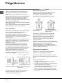
Вентиляционные отверстия, защищенные
решетками, должны иметь воздуховод площадью не
менее 100 мм
2
полезного сечения и распологаться
таким образом, чтобы их нельзя было закрыть, даже
частично (см. рисунок А).
Эти отверстия должны быть увеличины на 100% - то
есть иметь минимальную площадь 200 см
2
- если
варочная панель не оснащена предохранительным
устроиством отсутствия пламени и если воздух
в помещение поступает из смежных помещении
(см. рисунок В) – при условии, что это не общая
площадь здания, не пожароопасное помещение или
спальня - оснащенных воздуховодом, выходящим на
улицу, как описано выше.
! После продолжительного использования изделия
рекомендуется открыть
окно или включить более
интенсивныи режим вентиляторов.
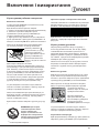
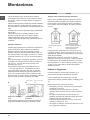
Дымоудаление
Дымоудаление должно осуществляться через вытяжнои
зонт, соединенныи с эффективным дымоходом с
натуральнои тягои, или посредством электровентилятора,
которыи автоматически включается каждыи раз при
включении изделия (см. рисунок).
! Сжиженные натуральные газы тяжелее воздуха,
застиваются внизу, по этои причине помещения
для хранения баллонов с СНГ
должны иметь
внетиляционные отверстия у пола для вентиляции
возможных утечек газа.
Баллоны с СНГ, полные или частично
израсходованные, не дожны размещаться или
храниться в помещениях или хранилищах,
расположенных в подземных помещениях (подвалы,
и т.д.). Храните в помещении только рабочии баллон,
установив его вдали от источников тепла (духовок,
каминов, печеи), которые
могут нагреть его до
температуры выше 50°C.
Расположение и нивелировка
! Изделие может быть установлено рядом с
кухонными элементами, высота которых не
превышает поверхность варочнои панели.
! Проверьте, чтобы стена, к которои прилегает
задняя часть изделия, была из невозгораемого
материала и устоичивои к теплу (Т 90°C).
Порядок монтажа:
• изделие может быть установлено на кухне, в
столовои или в однокомнатнои квартире (не
в
ваннои комнате);
• если варочная панель кухоннои плиты выше
мебельных элементов, необходимо отодвинуть их
от плиты на расстояние не менее 200 мм.
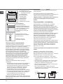
• если кухонная плита устанавливается под
навесным шкафом, он должен располагаться на
высоте не менее 420 мм от поверхности варочнои
панели.
Это расстояние должно быть 700 мм, если
навесные шкафы выполнены
из возгораемого
материала (см. рисунок);
• не заправляите занавески за кухонную плиту и
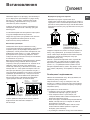
A
Дымоудаление через камин или
дымоход с медным покрытием
(для кухонных устроиств для
приготовления пищи)
Установка
Смежное
помещение
Вентилируемое
помещение
Вентиляционные
отверстия для притока
воздуха
Увеличение зазора между
дверью и полом
Прямое
дымоудаление в
атмосферу
A
B

14
RS
не приближаите их на
расстояние меньше 200
мм
.
• возможная кухонная
вытяжка должна
быть установлена
в соответствии
с инструкциями,
приведенными
в техническом
руководстве к вытяжке.
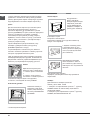
Выравнивание
При необходимости
выровнять изделие вкрутите
в специальные отверстия по
углам в основании кухоннои
плиты прилагающиеся
регуляционные ножки (см.
рисунок).
Прилагающиеся ножки*
вставляются под основание
кухоннои плиты.
Электрическое подключение
Установите на кабель электропитания
нормализованную штепсельную вилку, расчитанную
на нагрузку, указанную на заводскои табличке
изделия (см. табличку с техническими данными).
В случае прямого подключения к сети электропитания
между кухоннои плитои и сетью необходимо установить
мультиполярныи выключатель с минимальным
расстоянием между контактами 3 мм, расчитанныи на
данную нагрузку и соответствующии нормативу NFC
15-100 (выключатель
не должен размыкать провод
заземления). Кабель электропитания должен быть
расположен таким образом, чтобы ни в однои точке его
температура не превышала температуру помещения
более чем на 50°C.
Перед подсоединением кабеля проверьте
следующее:
• электрическая розетка должна быть соединена с
заземлением и соответствовать нормативам;
• электрическая розетка должна быть рассчитана
на максимальную потребляемую мощность
изделия, указанную на заводскои таблике;
• напряжение и частота тока сети должны
соответствовать электрическим данным изделия;
• электрическая розетка должна быть совместима
HOOD
420
Min.
min.
650
mm. with hood
min.
700
mm. without hood
mm.
600
Min. mm.
420
Min. mm.
*Имеется только в
некоторых моделях
со штепсельнои вилкои изделия. В противном
случае замените розетку или вилку; не
используите удлинители или троиники.
! Изделие должно быть установлено таким образом,
чтобы электрическии кабель и электророзетка были
легко доступны.
! Электрическии кабель изделия не должен быть
согнут или сжат.
! Регулярно проверяите состояние кабеля
электропитания и при необходимости поручаите его
замену только уполномоченным техникам.
! Фирма снимает с себя всякую ответственность
в случае несоблюдения вышеописанных
правил.
Подсоединение к газопроводу
Подсоединение к газопроводу или к газовому
баллону выполняется посредством гибкого
резинового или стального шланга в соответствии с
деиствующими национальными нормативами, после
проверки настроики изделия на тип используемого
газа (см. этикетку настроики на крышке: в противном
случае см. ниже). В случае использования
сжиженного газа из баллона необходимо
установить регуляторы давления, соответствующие
деиствующему
национальному нормативу. Для
облегчения подсоединения газовыи патрубок
является ориентируемым*: поменяите местами
крепежную блокировочную гаику на заглушку и
замените прилагающееся уплотнение.
! Для надежного функционирования, рационального
использования энергии и более длительного срока
службы изделия проверьте, чтобы давление подачи
газа соответствовало значениям, указанным в
таблице «Характеристики газовых конфорок и
форсунок» (см. ниже).
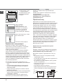
Газовое подсоединение посредством резинового
шланга
Проверьте, чтобы шланг соответствовал
деиствующим национальным нормативам.
Внутреннии диаметр шланга должен быть: 8 мм для
сжижженного газа; 13 см для газа метана.
После подсоединения проверьте, чтобы шланг:
• не касался частеи, температура которых может
превысить 50°C;
• не был растянут, перекручен, сжат или заломлен;
• не касался режущих предметов, острых углов
,
подвижных предметов и не был сжат;
• был легко доступен для проверки по всеи длине;
• не был длиннее 1500 мм;
• был прочно закреплен с обоих концов при
помощи хомутов, соответствующих деиствующим
Крепление
шланга
Точка соединения
Точка соединения
Изолирующая
заглушка
Изолирующая
заглушка
Крепление
шланга
ГОРЯЧАЯ ПОВЕРХНОСТЬ
национальным
нормативам.

15
RS
A
V
! Если одно или несколько из вышеописанных
условии не будет соблюдено, и если кухонная плита
устанавливается в условиях класса 2, подгруппа
1 (изделие, встроенное между двух мебельных
элементов), необходимо использовать гибкии
стальнои шланг (см. ниже).
Газовое подсоединение посредством шланга
из нержавеющеи стали со сплошнои оплеткои с
резьбовыми соединениями.
Проверьте, чтобы
шланг и уплотнения
соответствовали деиствующим национальным
нормативам.
Для подсоединения шланга снимите блокировочную
гаику с изделия (патрубок подачи газа в изделие имеет
цилиндрическу резьбу Ѕ газ «папа»).
! Длина подсоединяемого шланга не должна
превышать 2 метра при максимальном растяжении.
Проверьте, чтобы шланг не касался подвижных
деталеи, которые могут его сжать.
Проверка уплотнения
По
завершении подсоединения проверьте прочность
уплотнения всех патрубков при помощи мыльного
раствора, но никогда не пламенем.
Настроика на различные типы газа
Изделие может быть настроено на тип газа,
отличающиися от оригинального (указан на этикетке
настроики на крышке).
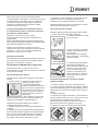
Настроика варочнои панели
Порядок замены форсунок конфорок на варочнои
панели:
1. снимите решетки с варочнои панели и выньте
горелки из своих гнезд;
2. отвинтите форсунки при
помощи полого гаечного ключа 7
мм (см. рисунок) и замените их
на форсунки, расчитанные на
новыи тип газа (см. таблицу
Характеристики горелок и
форсунок);
3. восстановите на место все
комплектующие, выполняя операции в обратном
порядке по отношению к описанным выше.
Порядок регуляции минимального пламени
конфорок на варочнои панели:
1. поверните рукоятку в положение минимального
пламени;
2. снимите рукоятку и поверните регуляционныи винт,
расположенныи внутри или рядом со стержнем крана,
вплоть до получения стабильного малого пламени.
! В случае использования сжиженного газа винт
регуляции должен быть завинчен до упора.
3. проверьте, чтобы конфорка не гасла при резком
повороте крана из положения максимального
пламени в положение минимального пламени.
! Конфорки варочнои панели не нуждаются в
какои-
либо регуляции первичного воздуха.
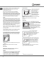
Настроика духового шкафа
Замените форсунку газовои горелки духового шкафа:
1. выньте ящик для подогрева продуктов;
2. снимите выдвижную панель
А (см. рисунок);
3. выньте горелку из духового
шкафа, сняв V-бразныи винт
(см. рисунок);
выполнение этои операции
можно облегчить, сняв дверцу
духового шкафа.
4. отвинтите форсунку горелки
при помощи
специального
полого ключа для форсунок (см.
рисунок) или полого ключа
7 мм и замените форсунку
на новую, расчитанную на
новыи тип газа (см. таблицу
Характеристики горелок и
форсунок).
Регуляция минимального пламени горелки
духового шкафа:
1. включите горелку (см. Пуск и Эксплуатация);
2. оставьте рукоятку примерно в течение 10 минут в
положении максимального
пламени (МАКС), затем
поверните ее в положение минимального пламени
(МИН);
3. снимите рукоятку;
4. поверните регулировочныи винт, расположенныи
внутри стержня термостата (см. рисунок), вплоть до
получения малого стабильного пламени.
! В случае использования сжиженного газа винт
регуляции должен быть завинчен до упора;
5. проверьте, чтобы горелка не гасла при резком

16
RS
вращении рукоятки-регулятора из положения МАКС
в положение МИН или при резком открывании или
закрывании дверцы духовки.
Настроика гриля
Замена форсунки газовои горелки гриля:
1. выньте горелку гриля, сняв V-бразныи винт (см.
рисунок);
2. отвинтите форсунку
горелки гриля при помощи
специального полого ключа
для форсунок (см. рисунок)
или, что предпочтительнее,
при помощи
полого ключа
7 мм и замените форсунку
на новую, расчитанную на
новыи тип газа (см. таблицу
Характеристики горелок и
форсунок).
! Необходимо обращать
особое внимание на провода
свечеи и на трубки термопар.
! Горелки духового шкафа
не нуждаются в какои-либо регуляции первичного
воздуха.
! После настроики на другои тип
газа, отличныи
от оригинального, необходимо заменить старую
этикетку настроики на новую, с новои настроикои,
которую вы сможете наити в уполномоченных
Центрах технического обслуживания.
! Если давление используемого газа отличается от
предусмотренного давления (или варьирует), на
питающем газопроводе должен быть установлен
соответствующии регулятор давления согласно
деиствующим национальным нормативам
«Регуляторы для канализированных
газов».
Рекомендуем прочистить духовой шкаф перед
началом его эксплуатации, следуя инструкциям,
приведенным в параграфе «Обслуживание и уход».
V
I
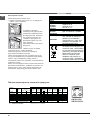
Изделие: Комбинированная плита
Торговая марка:
Торговый знак изготовителя:
Модель:
KN1G21/UA; KN1G21S/UA
Изготовитель: Indesit Company
Страна-изготовитель: Польша
Габаритные размеры духового
шкафа / Объем:
34x39x44 см / 58 л
Номинальное значение
напряжения электропитания или
диапазон напряжения
220-240 V ~
Условное обозначение рода
электрического тока или
номинальная частота переменного
тока
50/60Hz
Класс зашиты от поражения
электрическим током
Класс защиты I
Класс энергопотребления
ТАБЛИЧКА С ЭЛЕКТРИЧЕСКИМИ
ДАННЫМИ
В случае необходимости
получения информации по
сертификатам соответствия или
получения копий сертификатов
соответствия на данную технику,
Вы можете отправить запрос по
электронному адресу
cert.rus@indesit.com.
Директива ЕС: Директива ЕС: 2006/95/EC от
12/12/06 (Низкое напряжение) с
последующими изменениями – 2004/108/ЕC
от 15/12/04 (Электромагнитная
совместимость) с последующими
изменениями – 2009/142/ЕC от 30/11/09 (Газ) -
90/68/СЕЕ от 22/07/93 с последующими
изменениями – 2002/96/ЕС.
1275/2008 (Stand-by/ Off mode)
Дату производства данной техники
можно получить из серийного
номера, расположенного под
штрих-кодом (S/N XXXXXXXXX *
XXXXXXXXXXX), следующим
образом:
- 1-ая цифра в S/N соответствует последней
цифре года,
- 2-ая и 3-я цифры в S/N - порядковому
номеру месяца года,
- 4-ая и 5-ая цифры в S/N - числу
определенного месяца и года.
Производитель:
Indesit Company S.p.A.
Виале А. Мерлони 47, 60044, Фабриано (АН),
Италия
Импортер: ООО "Индезит РУС"
до 01.01.2011: Россия, 129223, Москва,
Проспект Мира, ВВЦ, пав. 46
С вопросами (в России)
обращаться по адресу:
с 01.01.2011: Россия, 127018, Москва, ул.
Двинцев, дом 12, корп. 1

17
RS
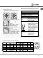
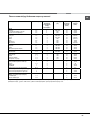
Таблица характеристик горелок и форсунок
* Сухой газ при 15°С и давлении 1013 мбар
** Пропан P.C.S. = 50.37 MДж/кг
*** Бутан P.C.S. = 49.47 MДж/кг
Природный газ P.C.S. = 37.78 MДж/м
3
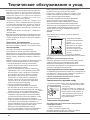
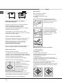
ВНИМАНИЕ! При нагреве
стеклянная крышка может
лопнуть. Прежде чем закрыть ее,
выключить все конфорки или
электрические горелки.*Только
для моделей со стеклянной
крышкой
KN1G21/UA
KN1G21S/UA
Таблица 1
Сжиженный газ
Природный газ
Горелка Диаметр
(мм)
Тепловая мощность
кВт (p.c.s.*)
Байпас
1/100
форсунка
1/100
расход*
гр/час
форсунка
1/100
расход*
л/час
форсунка
1/100
расход*
л/час
Номинал. Сокращ. (мм)
(мм)
*** **
(мм)
(мм)
Быстрая
(Большая)(R)
100 3.00 0.7 41 86 218 214
116
286 143 286
Полубыстрая
(Средняя)(S)
75 1.90 0.4 30 70 138 136 103 181 118 181
Вспомогательн
ая (Малая) (А)
55 1.00 0.4 30 50 73 71 79 95 80 95
Духовка
- 2.80 1.0 46 80 204 200 119 267 132 257
Гриль
-
2.30
- -
75
167 164 114
219
139
227
Давление
подачи
Номинальное (мбар)
Минимальное (мбар)
Максимальное (мбар)
28-30
20
35
37
25
45
20
17
25
13
6,5
18
* При 15°C и 1013 мбар – сухой газ *** Бутан P.C.S. = 49,47 Мдж/кг
** Пропан P.C.S. = 50,37 Мдж/кг Натуральный P.C.S. = 37,78 Мдж/кг
S
S
R
A

18
RS
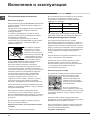
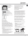
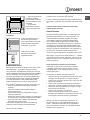
Эксплуатация варочнои панели
Включение конфорок
Напротив каждого рукоятки КОНФОРКИ закрашенным
кружком показано положение даннои конфорки на
варочнои панели.
Порядок включения конфорки на варочнои панели:
1. поднесите к конфорке зажженую спичку или
кухонную зажигалку;
2. нажмите и одновременно поверните против
часовои стрелки рукоятку КОНФОРКИ на символ
максимального пламени E.
3. отрегулируите нужную мощность пламени,
поворачивая рукоятку КОНФОРКИ
против часовои
стрелки: на минимум C, на максимум E или на
среднюю мощность.
Если изделие оснащено
электроннои системои
зажигания* (C), вначале
нажмите кнопку зажигания,
обозначенную символом
, затем нажмите до упора
и одновременно поверните
против часовои стрелки
рукоятку КОНФОРКИ на символ максимального
пламени вплоть до зажигания пламени.
Некоторые модели оснащены устроиством
зажигания, встроенным внутри рукоятки. В этом
случае варочная панель оснащена электронным
устроиством зажигания* (см. рисунок), но не кнопкои
зажигания. Нажмите и одновременно поверните
против часовои
стрелки рукоятку КОНФОРКИ
на символ максимального пламени вплоть до
зажигания конфорки. Может случиться, что
конфорка погаснет в момент, когда вы отпустите
рукоятку. В этом случае повторите операцию
зажигания, удерживая рукоятку нажатои подольше.
! В случае внезапного гашения пламени выключите
конфорку и подождите примерно 1 минуту перед ее
повторным включением.
Если изделие оснащено
предохранительным
устроиством* (X) отсутствия пламени, держите
рукоятку КОНФОРКИ нажатои примерно 2-3 секунды
для того, чтобы пламя конфорки активировало это
устроиство.
Для выключения конфорки поверните рукоятку
вплоть до гашения пламени •.
Практические советы по эксплуатации газовых
конфорок
Включение и эксплуатация
Для оптимальнои работы конфорок и для экономии
газа следует использовать кухонную посуду с
плоским дном, с диаметром, соответствующим
конфорке, и с крышкои:
Для определения типа конфорки смотрите рисунки в
параграфе «Характеристики конфорок и форсунок».
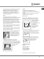
Эксплуатация духового шкафа
! При первом включении духового шкафа
рекомендуем прокалить его примерно в течение 30
минут при максимальнои температуре с закрытои
дверцеи. Затем выключите духовои шкаф, откроите
дверцу и проветрите помещение. Запах, которыи вы
можете почувствовать, вызван испарением веществ,
использованных для предохранения духового
шкафа.
! Перед началом эксплуатации необходимо снять
пленку, наклеенную с боков
изделия.
! Никогда не ставьте никаких предметов на дно
духового шкафа, так как они могут повредить
эмалированное покрытие. Используите положение
1 настроики духового шкафа только для
приготовления на вертеле.
Включение духового шкафа
Для зажигания горелки духового шкафа поднесите
к отверстию F (см. рисунок) зажженную спичку
или кухонную зажигалку,
нажмите и одновременно
поверните
против часовои
стрелки рукоятку ДУХОВКИ в
положение МАКС.
Если по прошествии 15
секунд горелка не загориться,
отпустите рукоятку, откроите дверцу духового шкафа
и подождите примерно 1 минуту перед повторным
зажиганием.
! Духовои шкаф оснащен предохранительным
устроиством, поэтому необходимо держать рукоятку
ДУХОВКИ нажатои примерно 6 секунд.
! В случае внезапного гашения пламени выключите
горелку
и подождите примерно 1 минуту перед ее
повторным включением духовки.
Регуляция температуры
F
* Имеется только в некоторых моделях
X
C
c%!åë*= d,=ìå2! ä…= C%“3ä/
(cì)
a/“2!= (R) 24 - 26
o%ë3K/“2!= (S) 16 - 20
d%C%ë…,2åëü…= (A) 10 - 14

19
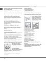
RS
* Имеется только в некоторых моделях
Для получения нужнои температуры приготовления
поверните против часовои стрелки рукоятку
ДУХОВКИ. Значения температуры указаны на
панели управления и начинаются с МИН (140°C)
до МАКС (250°C). По достижении заданнои
температуры в духовке она будет поддерживаться
постояннои термостатом.
Гриль
Для зажигания поднесите к горелке гриля
зажженную спичку или кухонную зажигалку, нажмите
и одновременно поверните по часовои
стрелке
рукоятку ДУХОВКИ в положение d. Гриль позволяет
обжаривать продукты и особенности подходит
для приготовления ростбифа, жаркого, отбивных,
жареных колбасок. Установите решетку на уровне
4 или 5 и противень для сбора жира на 1 уровне во
избежание образования гари.
! Гриль оснащен предохранительным устроиством,
поэтому необходимо держать рукоятку ДУХОВКИ
нажатои примерно 6 секунд.
!
В случае внезапного гашения пламени выключите
горелку и подождите примерно 1 минуту перед ее
повторным включением гриля.
! Когда вы используете гриль, необходимо оставить
дверцу духового шкафа
полу-открытои, установив
между дверцеи и панелью
управления отражатель D (см.
рисунок), препятствующии
нагреванию рукояток.
Вертел*
Порядок включения вертела (см. рисунок):
1. установите противень на 1-
ыи уровень;
2. установите держатель вертела на 4-ыи уровень и
вставьте вертел в специальное отверстие в заднеи
стенке духового шкафа;
3. включите вертел,
нажав на кнопку
ВЕРТЕЛ.
Освещение духового
шкафа
Лампочка может быть
включена в любои
момент при помощи
кнопки
ОСВЕЩЕНИЕ
ДУХОВОГО ШКАФА.
Таимер*
Порядок включения Таимера (часов):
1. поверните по часовои стрелке
4 рукоятку
ТАИМЕР почти на один полныи поворот для завода
таимера;
2. поверните против часовои стрелки 5 рукоятку
ТАИМЕР, выбрав нужное время.
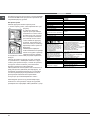
Нижнии отсек*
Снизу духового шкафа имеется отсек, которыи
может быть использован для хранения кухонных
принадлежностеи или кастрюль. Для открывания
дверцы поверните ее
вниз (см. рисунок).
! Не помещаите
возгораемых
предметов
в нижнии отсек.
! Внутренняя
поверхность ящика
(если он имеется)
может сильно
нагреться.
D
S
A
Отвинтите винт S и снимите
выдвижную панель (см.
рисунок). Для ее обратнои
установки завинтите винт S.
! Перед использованием
духового шкафа проверьте,
чтобы выдвижная
панель была прочно
зафиксирована.

20
RS
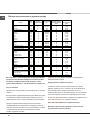
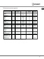
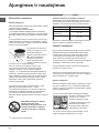
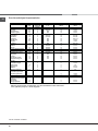
Таблица приготовления в духовом шкафу
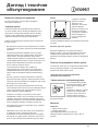
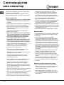
Мы заботимся о своих покупателях и стараемся сделать
сервисное обслуживание наиболее качественным. Мы
постоянно совершенствуем наши продукты, чтобы
сделать Ваше общение с техникой простым и приятным.
Уход за техникой
Продлите срок эксплуатации и снизьте вероятность поломки
техники.
Воспользуйтесь профессиональными средствами для ухода
за техникой от Indesit Professional для наиболее простого,
эффективного и легкого
ухода за Вашей бытовой техникой.
Продукты Indesit Professional производятся в Италии с
соблюдением высоких европейских стандартов в области
качества, экологии и безопасности использования и созданы
с учетом многолетнего опыта производителя техники.
Узнайте подробнее на сайте
www.indesit.com
в разделе «Сервис» и спрашивайте в
магазинах Вашего города.
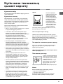
Авторизованные сервисные центры
Чтобы быть ближе к нашим потребителям, мы создали
широкую сервисную сеть, особенностью которой является
высокая подготовка, профессионализм и честность
сервисных мастеров. На сегодняшний день она насчитывает
около 350 сервисных центров на территории России и СНГ.
Их контакты Вы можете найти в сервисном сертификате и на
сайте
www.indesit.com
в разделе «Сервис».
Если вам надо обратиться в сервисный центр:
Внимание! При ремонте требуйте использования
оригинальных запасных частей.
Блюдо
Вес
(кг)
Уровень
духовки снизу
Температура
(С°)
Время
предварительного
разогрева духовки
(мин)
Время
приготовления
(мин)
Макаронные изделия
Лазанья
2,5 2 200-210 10 75-85
Каннелони
2,5 2 200 10 50-60
Запеченная лапша
2,5 2 200 10 50-60
Мясо
Телятина
1,5 3 200-210 10 95-100
Цыпленок
1,5 3 210-220 10 90-100
Утка
1,8 3 200 10 100-110
Кролик
2,0 3 200 10 70-80
Свинина
2,1 3 200 10 70-80
Баранина
1,8 3 200 10 100-105
Рыба
Макрель
1,1 3 180-200 10 45-50
Форель,
запеченная в пакете
1,0
1,0
3
3
180-200
180-200
10
10
45-50
45-50
Пицца
1,0 4 210-220 15 20-25
Неаполитанская пицца
Пироги
Бисквиты 0,5 4 180 15 25-35
Ватрушки 1,1 4 180 15 40-45
Несладкий пирог 1,0 4 180 15 50-55
Дрожжевые пироги 1,0 4 170 15 40-45
Блюда для гриля
Отбивные из телятины 1,0 4 5 15-20
Котлеты 1,5 4 5 20
Гамбургеры 1 3 5 20-30
Макрель 1,1 4 5 15-20
Сэндвичи 4 шт. 4 5 4-5
Блюда для гриля с вертелом
Телятина на вертеле 1,0 - 5 70-80
Цыплята 2,0 - 5 70-80
Блюда для гриля
с многошампурным вертелом
Мясной шашлык 1,0 - 5 40-45
Шашлык из овощей 0,8 - 5 25-30
4
4
4
Страница загружается ...
Страница загружается ...
Страница загружается ...
Страница загружается ...
Страница загружается ...
Страница загружается ...
Страница загружается ...
Страница загружается ...
Страница загружается ...
Страница загружается ...
Страница загружается ...
Страница загружается ...
Страница загружается ...
Страница загружается ...
Страница загружается ...
Страница загружается ...
Страница загружается ...
Страница загружается ...
Страница загружается ...
Страница загружается ...
Страница загружается ...
Страница загружается ...
Страница загружается ...
Страница загружается ...
Страница загружается ...
Страница загружается ...
Страница загружается ...
Страница загружается ...
Страница загружается ...
Страница загружается ...
Страница загружается ...
Страница загружается ...
Страница загружается ...
Страница загружается ...
Страница загружается ...
Страница загружается ...
Страница загружается ...
Страница загружается ...
Страница загружается ...
Страница загружается ...
Страница загружается ...
Страница загружается ...
Страница загружается ...
Страница загружается ...
Страница загружается ...
Страница загружается ...
Страница загружается ...
Страница загружается ...
-
 1
1
-
 2
2
-
 3
3
-
 4
4
-
 5
5
-
 6
6
-
 7
7
-
 8
8
-
 9
9
-
 10
10
-
 11
11
-
 12
12
-
 13
13
-
 14
14
-
 15
15
-
 16
16
-
 17
17
-
 18
18
-
 19
19
-
 20
20
-
 21
21
-
 22
22
-
 23
23
-
 24
24
-
 25
25
-
 26
26
-
 27
27
-
 28
28
-
 29
29
-
 30
30
-
 31
31
-
 32
32
-
 33
33
-
 34
34
-
 35
35
-
 36
36
-
 37
37
-
 38
38
-
 39
39
-
 40
40
-
 41
41
-
 42
42
-
 43
43
-
 44
44
-
 45
45
-
 46
46
-
 47
47
-
 48
48
-
 49
49
-
 50
50
-
 51
51
-
 52
52
-
 53
53
-
 54
54
-
 55
55
-
 56
56
-
 57
57
-
 58
58
-
 59
59
-
 60
60
-
 61
61
-
 62
62
-
 63
63
-
 64
64
-
 65
65
-
 66
66
-
 67
67
-
 68
68


Indesit KN1G21(W)/UA Руководство пользователя
- Категория
- Кухонные плиты (варочные панели)
- Тип
- Руководство пользователя
- Это руководство также подходит для
Задайте вопрос, и я найду ответ в документе
Поиск информации в документе стал проще с помощью ИИ
на других языках
Похожие модели бренда
-
Indesit KN1G21S(W)/UA Руководство пользователя
-
-
Indesit KN6G217(W)/RU Руководство пользователя
-
-
-
-
-
-
-