MSI B450 TOMAHAWK MAX Инструкция по применению

Категория
Материнские платы
Тип
Инструкция по применению

Это руководство также подходит для

I
Quick Start
Quick Start
Thank you for purchasing the MSI
®
B450 TOMAHAWK MAX
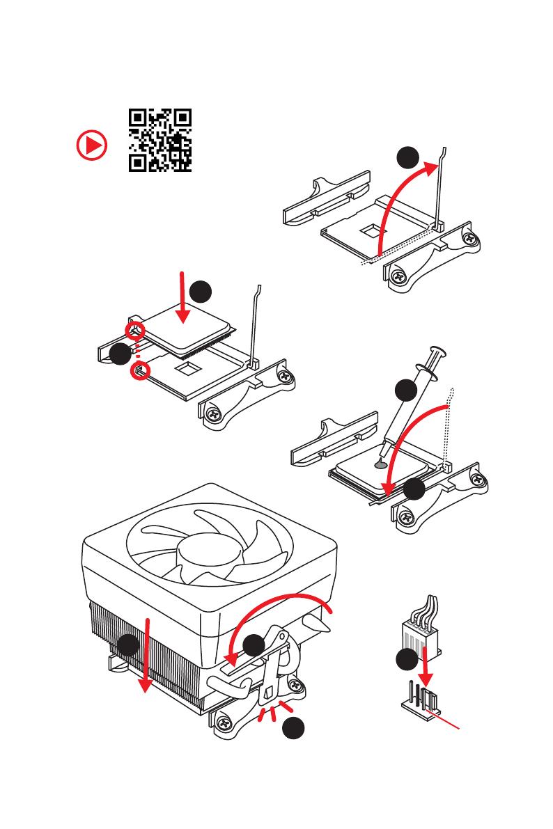
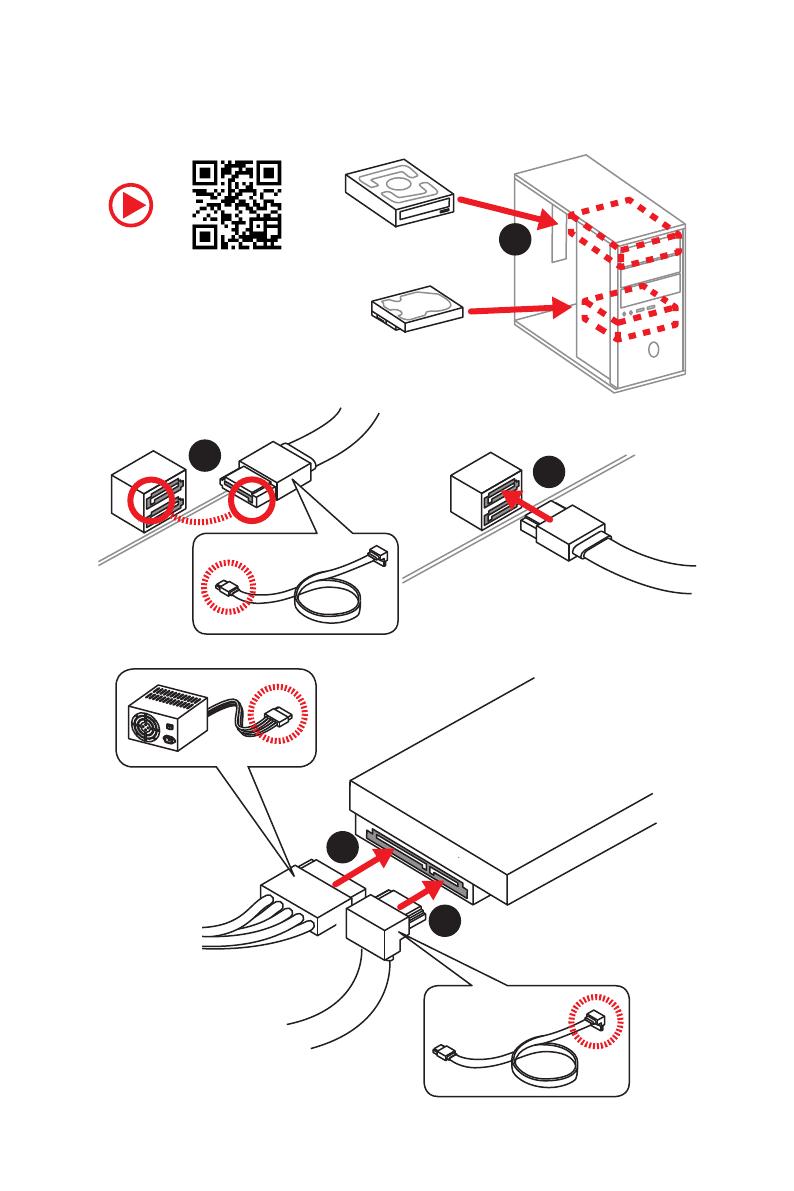
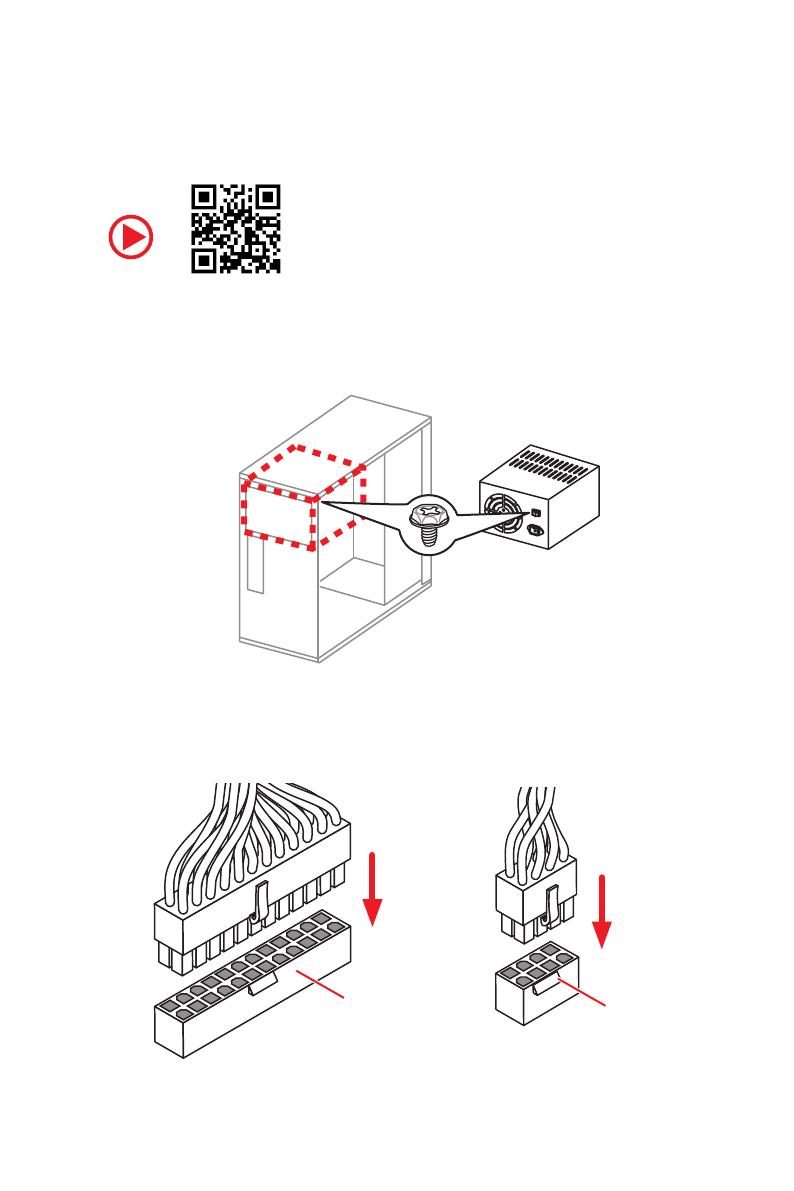
motherboard. This Quick Start section provides demonstration
diagrams about how to install your computer. Some of the
installations also provide video demonstrations. Please link to the
URL to watch it with the web browser on your phone or tablet. You
may have even link to the URL by scanning the QR code.
Kurzanleitung
Danke, dass Sie das MSI
®
B450 TOMAHAWK MAX Motherboard
gewählt haben. Dieser Abschnitt der Kurzanleitung bietet eine Demo
zur Installation Ihres Computers. Manche Installationen bieten
auch die Videodemonstrationen. Klicken Sie auf die URL, um diese
Videoanleitung mit Ihrem Browser auf Ihrem Handy oder Table
anzusehen. Oder scannen Sie auch den QR Code mit Ihrem Handy,
um die URL zu öffnen.
Présentation rapide
Merci davoir choisi la carte mère MSI
®
B450 TOMAHAWK MAX.
Ce manuel fournit une rapide présentation avec des illustrations
explicatives qui vous aideront à assembler votre ordinateur. Des
tutoriels vidéo sont disponibles pour certaines étapes. Cliquez sur
le lien fourni pour regarder la vidéo sur votre téléphone ou votre
tablette. Vous pouvez également accéder au lien en scannant le QR
code qui lui est associé.
Быстрый старт
Благодарим вас за покупку материнской платы MSI
®
B450
TOMAHAWK MAX. В этом разделе представлена информация,
которая поможет вам при сборке комьютера. Для некоторых
этапов сборки имеются видеоинструкции. Для просмотра
видео, необходимо открыть соответствующую ссылку в
веб-браузере на вашем телефоне или планшете. Вы также
можете выполнить переход по ссылке, путем сканирования
QR-кода.
II
Quick Start
Installing a Processor/ Installation des Prozessors/ Installer un
processeur/ Установка процессора
https://youtu.be/Xv89nhFk1vc
1
2
3
6
4
5
7
8
9
CPU_FAN1
III
Quick Start
If you are installing the screw-type CPU heatsink, please follow the figure below
to remove the retention module first and then install the heatsink.
Wenn Sie einen CPU-Kühler mit Schraubenbefestigung einsetzen, folgen Sie bitte
den Anweisungen unten um das Retention-Modul zu entfernen und den Kühler zu
installieren.
Si vous voulez installer un ventirad pour processeur à vis, veuillez suivre les
instructions ci-dessous pour dabord retirer le module de rétention puis installer le
ventirad.
В случае установки процессорного кулера с системой крепления на винтах,
следуйте указаниям на рисунке ниже для снятия пластикового модуля
крепления. Затем установите кулер.
1
2
3
IV
Quick Start
Installing DDR4 memory/ Installation des DDR4-Speichers/
Installer une mémoire DDR4/ Установка памяти DDR4
http://youtu.be/T03aDrJPyQs
DIMMB2 DIMMB2
DIMMB1
DIMMA2 DIMMA2 DIMMA2
DIMMA1
1
1
2
2
3
3
V
Quick Start
Connecting the Front Panel Header/ Anschließen der
Frontpanel-Stiftleiste/ Connecter un connecteur du panneau
avant/ Подключение разъемов передней панели
http://youtu.be/DPELIdVNZUI
RESET SW
POWER SW
POWER LED+
POWER LED-
HDD LED
HDD LED
RESET SW
JFP1
HDD LED
HDD LED -
HDD LED +
POWER LED -
POWER LED +
POWER LED
1
2 10
9
+
+
+-
--
-
+
Power LED
HDD LED Reset Switch
Reserved
Power Switch
JFP1
1 HDD LED + 2 Power LED +
3 HDD LED - 4 Power LED -
5 Reset Switch 6 Power Switch
7 Reset Switch 8 Power Switch
9 Reserved 10 No Pin
VII
Quick Start
1
2
3
4
5
Installing SATA Drives/ Installation der SATA-Laufwerke/
Installer le disque dur SATA/ Установка дисков SATA
http://youtu.be/RZsMpqxythc
IX
Quick Start
Connecting Peripheral Devices/ Peripheriegeräte/
Connecter un périphérique anschliessen/ Подключение
периферийных устройств
Processor with integrated
graphics
X
Quick Start
Connecting the Power Connectors/ Stromanschlüsse
anschliessen/ Connecter les câbles du module dalimentation/
Подключение разъемов питания
http://youtu.be/gkDYyR_83I4
ATX_PWR1
CPU_PWR1
8
Package contents
Package contents
Please check the contents of your motherboard package. It should contain:
y Motherboard
y Driver DVD
y User Manual
y Quick Installation Guide
y I/O Shielding
y SATA 6G Cable x2
y Case Badge
y Product Registration Card
y M.2 Screw x1
Important
If any of the above items are damaged or missing, please contact your retailer.
11
Rear I/O Panel
Audio jacks to headphone and microphone diagram
Audio jacks to stereo speakers diagram
Audio jacks to 7.1-channel speakers diagram
AUDIO INPUT
Rear Front
Side Center/
Subwoofer
AUDIO INPUT
12
Overview of Components
BAT1
JFP2
JFP1
SATA56
SATA34
CPU_FAN1
SYS_FAN1
PUMP_FAN1
JRGB2
PCI_E1
PCI_E2
PCI_E3
PCI_E4
PCI_E5
JBAT1
JAUD1
JTPM1
Processor
Socket
CPU_PWR1
DIMMA1
SYS_FAN4
M2_1
DIMMA2
DIMMB1
DIMMB2
JUSB3
SATA2
JUSB2
JUSB1
SATA1
JRGB1
SYS_FAN2
JCOM1
ATX_PWR1
SYS_FAN3
JCI1
18
Overview of Components
24
131
12
ATX_PWR1
1 +3.3V 13 +3.3V
2 +3.3V 14 -12V
3 Ground 15 Ground
4 +5V 16 PS-ON#
5 Ground 17 Ground
6 +5V 18 Ground
7 Ground 19 Ground
8 PWR OK 20 Res
9 5VSB 21 +5V
10 +12V 22 +5V
11 +12V 23 +5V
12 +3.3V 24 Ground
5
4 1
8
CPU_PWR1
1 Ground 5 +12V
2 Ground 6 +12V
3 Ground 7 +12V
4 Ground 8 +12V
Important
Make sure that all the power cables are securely connected to a proper ATX power
supply to ensure stable operation of the motherboard.
CPU_PWR1, ATX_PWR1: Power Connectors
These connectors allow you to connect an ATX power supply.
19
Overview of Components
JUSB1~2: USB 2.0 Connectors
These connectors allow you to connect USB 2.0 ports on the front panel.
1
2 10
9
1 VCC 2 VCC
3 USB0- 4 USB1-
5 USB0+ 6 USB1+
7 Ground 8 Ground
9 No Pin 10 NC
Important
y
Note that the VCC and Ground pins must be connected correctly to avoid possible
damage.
y
In order to recharge your iPad,iPhone and iPod through USB ports, please install
MSI
®
SUPER CHARGER utility.
JUSB3: USB 3.2 Gen1 Connector
This connector allows you to connect USB 3.2 Gen1 ports on the front panel.
Important
Note that the Power and Ground pins must be connected correctly to avoid possible
damage.
1
10
11
20
1 Power 11 USB2.0+
2 USB3_RX_DN 12 USB2.0-
3 USB3_RX_DP 13 Ground
4 Ground 14 USB3_TX_C_DP
5 USB3_TX_C_DN 15 USB3_TX_C_DN
6 USB3_TX_C_DP 16 Ground
7 Ground 17 USB3_RX_DP
8 USB2.0- 18 USB3_RX_DN
9 USB2.0+ 19 Power
10 NC 20 No Pin
22
Overview of Components
JBAT1: Clear CMOS (Reset BIOS) Jumper
There is CMOS memory onboard that is external powered from a battery located on
the motherboard to save system configuration data. If you want to clear the system
configuration, set the jumper to clear the CMOS memory.
Keep Data
(default)
Clear CMOS/
Reset BIOS
Resetting BIOS to default values
1. Power off the computer and unplug the power cord.
2. Use a jumper cap to short JBAT1 for about 5-10 seconds.
3. Remove the jumper cap from JBAT1.
4. Plug the power cord and Power on the computer.
1
2 14
13
1 LPC Clock 2 3V Standby power
3 LPC Reset 4 3.3V Power
5 LPC address & data pin0 6 Serial IRQ
7 LPC address & data pin1 8 5V Power
9 LPC address & data pin2 10 No Pin
11 LPC address & data pin3 12 Ground
13 LPC Frame 14 Ground
JTPM1: TPM Module Connector
This connector is for TPM (Trusted Platform Module). Please refer to the TPM security
platform manual for more details and usages.
5
Spezifikationen
Fortsetzung der vorherigen Seite
Hintere Ein-/ und
Ausgänge
y 1x Flash BIOS Taste
y 1x PS/2 Tastatur/ Maus-Combo-Anschluss
y 2x USB 2.0 Typ-A Anschlüsse
y 1x DVI-D Anschluss
y 1x HDMI
Anschluss
y 2x USB 3.2 Gen1 Typ-A Anschlüsse
y 1x LAN (RJ45) Anschluss
y 1x USB 3.2 Gen2 Typ-A Anschluss
y 1x USB 3.2 Gen2 Typ-C Anschluss
y 6x Audiobuchsen
Interne Anschlüsse
y 1x 24-poliger ATX Stromanschluss
y 1x 8-poliger ATX 12 V Stromanschluss
y 6x SATA 6Gb/s Anschlüsse
y 2x USB 2.0 Anschlüsse (unterstützt zusätzliche 4 USB 2.0
-Ports)
y 1x USB 3.2 Gen1 Anschluss (unterstützt zusätzliche 2 USB
3.2 Gen1-Ports)
y 1x 4-poliger CPU-Lüfter-Anschluss
y 1x 4-poliger Anschluss für die Wasserpumpe
y 4x 4-polige System-Lüfter-Anschlüsse
y 1x TPM Anschluss
y 1x Audioanschluss des Frontpanels
y 2x System-Panel-Anschlüsse
y 1x Gehäusekontaktschalter
y 1x Serieller Anschluss
y 1x Clear CMOS Steckbrücke
y 2x 5050 RGB LED Streifen 12 V Anschlüsse
E/A Anschluss NUVOTON NCT6797 Controller Chip
Hardware Monitor
y CPU/System Temperaturerfassung
y CPU/System Geschwindigkeitserfassung
y CPU/System Lüfterdrehzahlregelung
Fortsetzung auf der nächsten Seite
11
Rückseite E/A
Audiobuchsen für den Anschluss von einem Kopfhörer und Mikrofon
Audiobuchsen für Stereo-Lautsprecher
Audiobuchsen für 7.1 Kanal Anlage
AUDIO INPUT
Rear Front
Side Center/
Subwoofer
AUDIO INPUT
18
Übersicht der Komponenten
24
131
12
ATX_PWR1
1 +3.3V 13 +3.3V
2 +3.3V 14 -12V
3 Ground 15 Ground
4 +5V 16 PS-ON#
5 Ground 17 Ground
6 +5V 18 Ground
7 Ground 19 Ground
8 PWR OK 20 Res
9 5VSB 21 +5V
10 +12V 22 +5V
11 +12V 23 +5V
12 +3.3V 24 Ground
5
4 1
8
CPU_PWR1
1 Ground 5 +12V
2 Ground 6 +12V
3 Ground 7 +12V
4 Ground 8 +12V
Wichtig
Stellen Sie sicher, dass alle Anschlüsse mit den richtigen Anschlüssen des Netzteils
verbunden sind, um einen stabilen Betrieb der Hauptplatine sicherzustellen.
CPU_PWR1, ATX_PWR1: Stromanschlüsse
Mit diesen Anschlüssen verbinden Sie die ATX Stromstecker.
6
Spécifications
Suite du tableau de la page précédente
Dimensions
y Format ATX
y 30,5 cm x 24,4 cm (12 x 9,6)
Fonctions BIOS
y 1 x flash BIOS 256 Mb
y UEFI AMI BIOS
y ACPI 6.1, SM BIOS 2.8
y Multilingue
Logiciel
y Pilotes
y APP MANAGER
y SUPER CHARGER
y COMMAND CENTER
y LIVE UPDATE 6
y SMART TOOL
y RAMDISK
y X-BOOST
y GAMING APP
y MYSTIC LIGHT
y Open Broadcaster Software (OBS)
y CPU-Z MSI GAMING
y Norton
Internet Security Solution
y Google Chrome
, Google Toolbar et Google Drive
Fonctions spéciales
y Audio
Audio Boost
y Stockage
Turbo M.2
StoreMI
y Ventilateur
Ventilateurs pour la pompe
Contrôle des ventilateurs GAMING
Suite du tableau sur la page suivante
18
Vue densemble des composants
24
131
12
ATX_PWR1
1 +3.3V 13 +3.3V
2 +3.3V 14 -12V
3 Ground 15 Ground
4 +5V 16 PS-ON#
5 Ground 17 Ground
6 +5V 18 Ground
7 Ground 19 Ground
8 PWR OK 20 Res
9 5VSB 21 +5V
10 +12V 22 +5V
11 +12V 23 +5V
12 +3.3V 24 Ground
5
4 1
8
CPU_PWR1
1 Ground 5 +12V
2 Ground 6 +12V
3 Ground 7 +12V
4 Ground 8 +12V
Important
Veuillez vous assurer que tous les câbles dalimentation sont branchés aux
connecteurs adéquats afin garantir une opération stable de la carte mère.
CPU_PWR1, ATX_PWR1 : Connecteurs dalimentation
Ces connecteurs vous permettent de relier une alimentation ATX.
1 / 1

MSI B450 TOMAHAWK MAX Инструкция по применению

Категория
Материнские платы
Тип
Инструкция по применению
Это руководство также подходит для

Задайте вопрос, и я найду ответ в документе

Поиск информации в документе стал проще с помощью ИИ

Спросите документ