Yamaha YST-SW215 Инструкция по применению
- Категория
- Сабвуферы
- Тип
- Инструкция по применению
Это руководство также подходит для

YAMAHA ELECTRONICS CORPORATION, USA 6660 ORANGETHORPE AVE., BUENA PARK, CALIF. 90620, U.S.A.
YAMAHA CANADA MUSIC LTD. 135 MILNER AVE., SCARBOROUGH, ONTARIO M1S 3R1, CANADA
YAMAHA ELECTRONIK EUROPA G.m.b.H. SIEMENSSTR. 22-34, 25462 RELLINGEN BEI HAMBURG, F.R. OF GERMANY
YAMAHA ELECTRONIQUE FRANCE S.A. RUE AMBROISE CROIZAT BP70 CROISSY-BEAUBOURG 77312 MARNE-LA-VALLEE CEDEX02, FRANCE
YAMAHA ELECTRONICS (UK) LTD. YAMAHA HOUSE, 200 RICKMANSWORTH ROAD WATFORD, HERTS WD1 7JS, ENGLAND
YAMAHA SCANDINAVIA A.B. J A WETTERGRENS GATA 1, BOX 30053, 400 43 VÄSTRA FRÖLUNDA, SWEDEN
YAMAHA MUSIC AUSTRALIA PTY, LTD. 17-33 MARKET ST., SOUTH MELBOURNE, 3205 VIC., AUSTRALIA
Printed in Indonesia WB35950
G
YST-SW315
YST-SW215
YST-SW315/YST-SW215
Subwoofer System
Enceinte a caisson de grave
OWNER S MANUAL
MODE D EMPLOI
BEDIENUNGSANLEITUNG
BRUKSANVISNING
MANUALE DI ISTRUZIONI
MANUAL DE INSTRUCCIONES
GEBRUIKSAANWIJZING

1
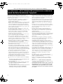
Thank you for selecting this YAMAHA subwoofer system.
Please read the following operating precautions
before use. YAMAHA will not be held responsible
for any damage and/or injury caused by not
following the cautions below.
• To assure the finest performance, please read this
manual carefully. Keep it in a safe place for future
reference.
• Install this unit in a cool, dry, clean place - away from
windows, heat sources, sources of excessive vibration,
dust, moisture and cold. Avoid sources of humming
(transformers, motors). To prevent fire or electrical
shock, do not expose this unit to rain or water.
• Never open the cabinet. If something drops into the set,
contact your dealer.
• The voltage to be used must be the same as that specified
on the rear panel. Using this unit with a higher voltage
than specified is dangerous and may cause a fire and/or
electric shock.
• To reduce the risk or fire or electric shock, do not expose
this unit to rain or moisture.
• Do not use force on switches, controls or connection
wires. When moving the unit, first disconnect the power
plug and the wires connected to other equipments.
Never pull the wires themselves.
• When not planning to use this unit for a long period (ie.,
vacation, etc.), disconnect the AC power plug from the
wall outlet.
• To prevent lightning damage, disconnect the AC power
plug when there is an electric storm.
• Since this unit has a built-in power amplifier, heat will
radiate from the rear panel. Place the unit apart from the
walls, allowing at least 20 cm of space above, behind and
on both sides of the unit to prevent fire or damage.
Furthermore, do not position with the rear panel facing
down on the floor or other surfaces.
• Do not cover the rear panel of this unit with a newspaper,
a tablecloth, a curtain, etc. in order not to obstruct heat
radiation. If the temperature inside the unit rises, it may
cause fire, damage to the unit and/or personal injury.
• Do not place the following objects on this unit:
Glass, china, small metallic etc.
If glass etc. falls by vibrations and breaks, it may cause
bodily injury.
A burning candle etc.
If the candle falls by vibrations, it may cause fire and
bodily injury.
A vessel with water in it
If the vessel falls by vibrations and water spills, it may
cause damage to the speaker, and/or you may get an
electric shock.
• Do not place this unit where foreign objects such as
water drips might fall. It might cause a fire, damage to
this unit, and/or personal injury.
• Never put a hand or a foreign object into the YST port
located on the right side of this unit. When moving this
unit, do not hold the port as it might cause personal
injury and/or damage to this unit.
• Never place a fragile object near the YST port of this
unit. If the object falls or drops by the air pressure, it may
cause damage to the unit and/or personal injury.
• Never open the cabinet. It might cause an electric shock
since this unit uses a high voltage. It might also cause
personal injury and/or damage to this unit.
• When using a humidifier, be sure to avoid condensation
inside this unit by allowing enough spaces around this
unit or avoiding excess humidification. Condensation
might cause a fire, damage to this unit, and/or electric
shock.
• Super-bass frequencies reproduced by this unit may
cause a turntable to generate a howling sound. In such a
case, move this unit away from the turntable.
• This unit may be damaged if certain sounds are
continuously outputted at high volume level. For
example, if 20 Hz-50 Hz sine waves from a test disc,
bass sounds from electronic instruments, etc. are
continuously outputted, or when the stylus of a turntable
touches the surface of a disc, reduce the volume level to
prevent this unit from being damaged.
• If you hear distorted noise (i.e., unnatural, intermittent
“rapping” or “hammering” sounds) coming from this
unit, reduce the volume level. Extremely loud playing of
a movie soundtrack’s low frequency, bass-heavy sounds
or similarly loud popular music passages can damage
this speaker system.
• Vibration generated by super-bass frequencies may
distort images on a TV. In such a case, move this unit
away from the TV set.
• Do not attempt to clean this unit with chemical solvents
as this might damage the finish. Use a clean, dry cloth.
• Be sure to read the “TROUBLESHOOTING” section
regarding common operating errors before concluding
that the unit is faulty.
• Secure placement or installation is the owner’s
responsibility. YAMAHA shall not be liable for any
accident caused by improper placement or
installation of speakers.
CAUTION: Read this before operating your unit
YST-SW315_215_03.25_tab.fm Page 1 Friday, April 4, 2003 1:20 PM

2
English
• VOLTAGE SELECTOR
(For China, Korea and General models)
The voltage selector switch on the rear panel of this
unit must be set for your local main voltage BEFORE
plugging this unit into the AC main supply. Voltages
are 110/120/220/240 V AC, 50/60 Hz.
For U.K. customers
If the socket outlets in the home are not suitable for the
plug supplied with this appliance, it should be cut off and
an appropriate 3 pin plug fitted. For details, refer to the
instructions described below.
Note: The plug severed from the mains lead must be
destroyed, as a plug with bared flexible cord is hazardous
if engaged in a live socket outlet.
SPECIAL INSTRUCTIONS FOR U.K. MODEL
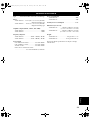
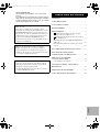
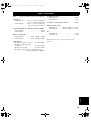
CAUTION ......................................................................1
FEATURES ....................................................................3
SUPPLIEDACCESSORIES ...........................................3
PLACEMENT ................................................................4
CONNECTIONS ...........................................................5
Connecting to line output (pin jack) terminals
of the amplifier .................................................... 5
Connecting to speaker output terminals of
the amplifier .......................................................... 8
Connecting to the INPUT1/ OUTPUT terminals
of the subwoofer .......................................................12
Plug in the subwoofer to the AC outlet ....................12
CONTROLSANDTHEIRFUNCTIONS ..................13
AUTOMATICPOWER-SWITCHING
FUNCTION .................................................................15
ADJUSTINGTHESUBWOOFER
BEFOREUSE .............................................................16
Frequency characteristics .........................................17
ADVANCEDYAMAHAACTIVESERVO
TECHNOLOGY ..........................................................18
TROUBLESHOOTING...............................................19
SPECIFICATIONS.......................................................2 0
Standby mode
When this unit is turned off by pressing the
STANDBY/ON button on the front panel, this unit
consumes a small amount of power. This state is called
the standby mode. This unit’s power supply is
completely cut off from the AC line only when the
POWER switch on the rear panel is set in the OFF
position or the AC power cord is disconnected.
This unit features a magnetically shielded design, but
there is still a chance that placing it too close to a TV
set might impair picture color. Should this happen,
move this unit away from the TV set.
IMPORTANT:
THE WIRES IN MAINS LEAD ARE COLOURED
IN ACCORDANCE WITH THE FOLLOWING
CODE:
Blue: NEUTRAL
Brown: LIVE
As the colours of the wires in the mains lead of this
apparatus may not correspond with the coloured
markings identifying the terminals in your plug,
proceed as follows: The wire which is coloured
BLUE must be connected to the terminal which is
marked with the letter N or coloured BLACK. The
wire which is coloured BROWN must be connected
to the terminal which is marked with the letter L or
coloured RED. Making sure that neither core is
connected to the earth terminal of the three pin plug.
For Canadian Customers
To prevent electric shock, match wide blade of plug
to wide slot and fully insert.
This Class B digital apparatus complies with
Canadian ICES-003.
CONTENTS
1
2
YST-SW315_215_03.25_tab.fm Page 2 Tuesday, March 25, 2003 4:07 PM

3
• This subwoofer system employs Advanced Yamaha
Active Servo Technology which Yamaha has developed
for reproducing higher quality super-bass sound. (Refer
to page 18 for details on Advanced Yamaha Active
Servo Technology.) This super-bass sound adds a more
realistic, theater-in-the-home effect to your stereo
system.
• This subwoofer can be easily added to your existing
audio system by connecting to either the speaker
terminals or the line output (pin jack) terminals of the
amplifier.
• For the effective use of the subwoofer, the subwoofer’s
super-bass sound should be matched to the sounds of
your main speakers. You can create the best sound
quality for various listening conditions by using the
HIGH CUT control and the PHASE switch.
• The Automatic power-switching function saves you the
trouble of pressing the STANDBY/ON button to turn the
power on and off.
• You can select bass effect suitable for the source by
using the B.A.S.S. button.
After unpacking, check that the following parts are
contained.
Non-skid pads
FEATURES
QD-Bass Technology
QD-Bass (Quatre Dispersion Bass) technology uses
square, pyramid-shaped reflective plates to radiate the
sound in four horizontal directions.
SUPPLIED ACCESSORIES
YST-SW315_215_03.25_tab-c.fm Page 3 Tuesday, April 15, 2003 11:02 AM

4
English
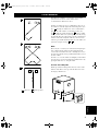
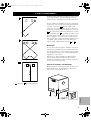
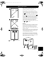
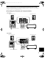
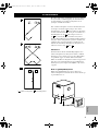
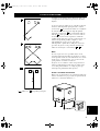
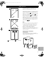
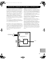
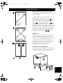
( : subwoofer, : main speaker)
One subwoofer will have a good effect on your audio
system, however, the use of two subwoofers is
recommended to obtain more effect.
If using one subwoofer, it is recommended to place it on
the outside of either the right or the left main speaker. (See
fig. .) If using two subwoofers, it is recommended to
place them on the outside of each main speaker. (See
fig. .) The placement shown in fig. is also possible,
however, if the subwoofer system is placed directly facing
the wall, the bass effect may die because the sound from it
and the sound reflected by the wall may cancel out each
other. To prevent this from happening, face the subwoofer
system at an angle as in fig. or .
Note
There may be a case that you cannot obtain enough super-
bass sounds from the subwoofer when listening in the
center of the room. This is because “standing waves” have
been developed between two parallel walls and they cancel
the bass sounds.
In such a case, face the subwoofer obliquely to the wall. It
also may be necessary to break up the parallel surfaces by
placing bookshelves etc. along the walls.
Use the non-skid pads
Put the provided non-skid pads at the four corners on the
bottom of the subwoofer to prevent the subwoofer from
moving by vibrations etc.
PLACEMENT
A
B
C
A
B C
A
B
YST-SW315_215_03.25_tab.fm Page 4 Tuesday, March 25, 2003 4:07 PM

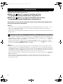
5
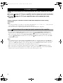
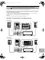
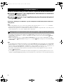
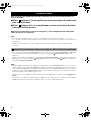
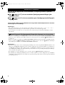
Choose one of the following two connecting methods that is more suitable for your audio
system.
■
Choose (pages 5-7) if your amplifier has line output (pin jack) terminal(s)
■ Choose (pages 8-11) if your amplifier has no line output (pin jack)
terminal
Caution: Unplug the subwoofer and other audio/video components before making
connections.
Notes
• All connections must be correct, that is to say L (left) to L, R (right) to R, “+” to “+” and “–” to “–”. Also, refer to the
owner’s manual of your component to be connected to the subwoofer.
• After all connections are completed, plug in the subwoofer and other audio/video components.
• To connect with a YAMAHA DSP amplifier (or AV receiver), connect the SUBWOOFER (or LOW PASS etc.)
terminal on the rear of the DSP amplifier (or AV receiver) to the /MONO INPUT2 terminal of the subwoofer.
• When connecting the subwoofer to the SPLIT SUBWOOFER terminals on the rear of the DSP amplifier, be sure to
connect the /MONO INPUT2 terminal to the “L” side and the INPUT2 terminal to the “R” side of the SPLIT
SUBWOOFER terminals.
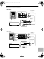
Notes
• Some amplifiers have line output terminals labeled PRE OUT. When you connect the subwoofer to the PRE OUT
terminals of the amplifier, make sure that the amplifier has at least two sets of PRE OUT terminals. If the amplifier has
only one set of PRE OUT terminals, do not connect the subwoofer to the PRE OUT terminals. Instead, connect the
subwoofer to the speaker output terminals of the amplifier. (Refer to pages 8-11.)
• When connecting to a monaural line output terminal of the amplifier, connect the /MONO INPUT2 terminal.
• When connecting to line output terminals of the amplifier, other speakers should not be connected to the OUTPUT
terminals on the rear panel of the subwoofer. If connected, they will not produce sound.
CONNECTIONS
1
2
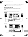
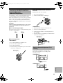
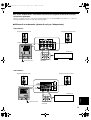
Connecting to line output (pin jack) terminals of the amplifier
1
L
L
R
L
YST-SW315_215_03.25_tab.fm Page 5 Tuesday, March 25, 2003 4:07 PM

6
English
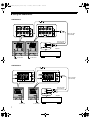
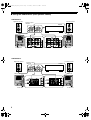
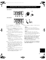
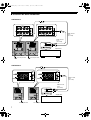
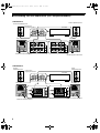
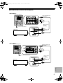
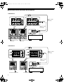
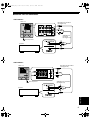
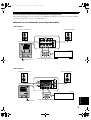
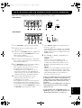
■ Using one subwoofer
<YST-SW315>
<YST-SW215>
CONNECTIONS
Subwoofer
Amplifier
To AC outlet
Mono pin cable
(not included)
Audio pin cable
(not included)
Subwoofer
Amplifier
To AC outlet
Mono pin cable
(not included)
Audio pin cable
(not included)
YST-SW315_215_03.25_tab.fm Page 6 Tuesday, March 25, 2003 4:07 PM

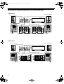
7
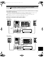
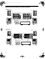
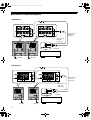
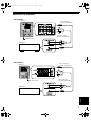
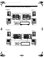
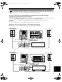
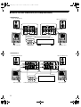
■ Using two subwoofers
<YST-SW315>
<YST-SW215>
CONNECTIONS
Amplifier
To AC outlet
To AC outlet
Mono pin cable
(not included)
Mono pin cable
(not included)
Amplifier
To AC outlet To AC outlet
Mono pin cable
(not included)
Mono pin cable
(not included)
YST-SW315_215_03.25_tab.fm Page 7 Tuesday, March 25, 2003 4:07 PM

8
English
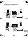
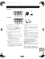
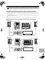
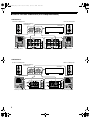
Select this method if your amplifier has no line output (pin jack) terminal.
If your amplifier has two sets of main speaker output terminals and both terminals can output
sound signals simultaneously.
• Connect one set of main speaker output terminals of the amplifier to the INPUT1 terminals of the subwoofer, and
connect the other set of main speaker output terminals of the amplifier to the main speakers.
• Set the amplifier so that both sets of main speaker output terminals output sound signals simultaneously.
Note
• If your amplifier has only one set of main speaker output terminals, see page 10.
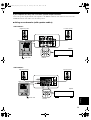
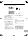
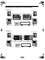
■ Using one subwoofer (with speaker cables)
<YST-SW315>
<YST-SW215>
CONNECTIONS
Connecting to speaker output terminals of the amplifier
2
Right main speaker Subwoofer
To AC outlet
Left main speaker
Amplifier
Speaker output
terminals
Amplifier
Right main speaker
Left main speaker
Subwoofer
To AC outlet
Speaker output
terminals
YST-SW315_215_03.25_tab-c.fm Page 8 Tuesday, April 15, 2003 1:44 PM

9
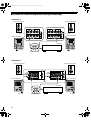
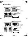
■ Using two subwoofers (with speaker cables)
<YST-SW315>
<YST-SW215>
CONNECTIONS
Right main speaker
Subwoofer
To AC outlet
Left main speaker
Amplifier
Speaker output
terminals
To AC outlet
Subwoofer
Amplifier
Right main speaker
Left main speaker
Subwoofer
To AC outlet
To AC outlet
Subwoofer
Speaker output
terminals
YST-SW315_215_03.25_tab.fm Page 9 Tuesday, March 25, 2003 4:07 PM

10
English
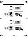
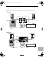
If your amplifier has only one set of main speaker output terminals.
Connect the speaker output terminals of the amplifier to the INPUT1 terminals of the subwoofer, and connect the
OUTPUT terminals of the subwoofer to the main speakers.
■ Using one subwoofer (with speaker cables)
<YST-SW315>
<YST-SW215>
CONNECTIONS
Right main speaker
Left main speaker
Subwoofer
Amplifier
Speaker output
terminals
To AC outlet
Right main speaker
Left main speaker
Subwoofer
Amplifier
Speaker output
terminals
To AC outlet
YST-SW315_215_03.25_tab.fm Page 10 Tuesday, March 25, 2003 4:07 PM

11
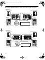
■ Using two subwoofers (with speaker cables)
<YST-SW315>
<YST-SW215>
CONNECTIONS
Right main speaker
Left main speaker
Subwoofer
Subwoofer
Speaker output
terminals
To AC outlet To AC outlet
Amplifier
Right main speaker
Left main speaker
Subwoofer
Speaker output
terminals
To AC outlet
To AC outlet
Amplifier
Subwoofer
YST-SW315_215_03.25_tab.fm Page 11 Tuesday, March 25, 2003 4:07 PM

12
English
For connection, keep the speaker cables as short as
possible. Do not bundle or roll up the excess part of the
cables. If the connections are faulty, no sound will be heard
from the subwoofer or the speakers, or both of them. Make
sure that the + and – polarity markings of the speaker
cables are observed and set correctly. If these cables are
reversed, the sound will be unnatural and lack bass.
Caution
Do not let the bare speaker wires touch each other, because
this could damage the subwoofer or the amplifier, or both of
them.
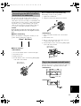
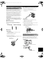
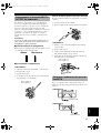
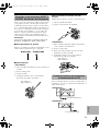
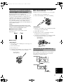
■ Before connecting
Remove the insulation coating at the extremity of each
speaker cable by twisting the coating off.
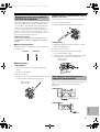
■ How to connect:
<YST-SW315>
1 Loosen the terminal’s knob, as shown in the figure.
2 Insert the bare wire.
3 Tighten the knob.
4 Test the firmness of the connection by pulling lightly
on the cable at the terminal.
U.S.A., Canada and Australia models only
Banana Plug conection are also possible.
1 Tighten the terminal knob.
2 Simply insert the banana plug into the terminal.
<YST-SW215>
1 Press and hold the terminal’s tab, as shown in the
figure.
2 Insert the bare wire.
3 Release your finger from the tab to allow it to lock
securely on the cable’s wire end.
4 Test the firmness of the connection by pulling lightly
on the cable at the terminal.
After all connections are completed, plug in the subwoofer
and other audio/video components to the AC outlet.
<YST-SW315>
<YST-SW215>
CONNECTIONS
Connecting to the INPUT1/OUTPUT
terminals of the subwoofer
Good
No Good
Red: positive (+)
Black: negative (
–
)
Plug in the subwoofer to the AC outlet
Red: positive (+)
Black: negative (
–
)
To AC outlet
To AC outlet
YST-SW315_215_03.25_tab.fm Page 12 Tuesday, March 25, 2003 4:07 PM

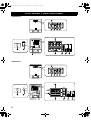
13
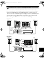
<YST-SW315>
<YST-SW215>
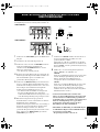
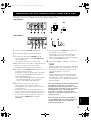
CONTROLS AND THEIR FUNCTIONS
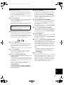
Front panel
Rear panel
(General model)
Front panel
Rear panel
(General model)
YST-SW315_215_03.25_tab.fm Page 13 Tuesday, March 25, 2003 4:07 PM

14
English
1 Power indicator
Lights up in green while the subwoofer is on.
Lights up in red while the subwoofer is set in the
standby mode by the operation of the automatic power-
switching function.
Goes off when the subwoofer is set in the standby
mode.
2 STANDBY/ON button
Press this button to turn on the power when the
POWER switch is set in the ON position. (The power
indicator lights up in green.)
Press again to set the subwoofer in the standby mode.
(The power indicator goes off.)
3 B.A.S.S. (Bass Action Selector System) button
When this button is pressed in to the MUSIC position,
the bass sound in audio software is well reproduced.
By pressing the button again so that it pops out at the
MOVIE position, the bass sound in video software is
well reproduced.
4 HIGH CUT control
Adjusts the high frequency cut off point.
Frequencies higher than the frequency selected by this
control are all cut off (and no output).
* One graduation of this control represents 10 Hz.
5 VOLUME control
Adjusts the volume level. Turn the control clockwise to
increase the volume, and counterclockwise to decrease
the volume.
6 VOLTAGE SELECTOR switch
(China, Korea and General models only)
If the preset setting of the switch is incorrect, set the
switch to the proper voltage (110V, 120V, 220V or
240V) of your area.
Consult your dealer if you are unsure of the correct
setting.
WARNING
Be sure to unplug the subwoofer before setting the
VOLTAGE SELECTOR switch correctly.
7 POWER switch
Normally, set this switch to the ON position to use the
subwoofer. In this state, you can turn on the subwoofer
or turn the subwoofer into the standby mode by
pressing the STANDBY/ON button. Set this switch to
the OFF position to completely cut off the subwoofer’s
power supply from the AC line.
8 OUTPUT (TO SPEAKERS) terminals
Can be used for connecting to the main speakers.
Signals from the INPUT1 terminals are sent to these
terminals.
(Refer to “CONNECTIONS” for details.)
9 INPUT1 (FROM AMPLIFIER) terminals
Used to connect the subwoofer with the speaker
terminals of the amplifier.
(Refer to “CONNECTIONS” for details.
0 INPUT2 terminals
Used to input line level signals from the amplifier.
(Refer to “CONNECTIONS” for details.)
A AUTO STANDBY (HIGH/LOW/OFF) switch
This switch is originally set to the OFF position. By
setting this switch to the HIGH or LOW position, the
subwoofer’s automatic power-switching function
operates as described on page 15. If you do not need
this function, leave this switch in the OFF position.
* Make sure to change the setting of this switch only
when the subwoofer is set in the standby mode by
pressing the STANDBY/ON button.
B PHASE switch
Normally this switch is to be set to the REV (reverse)
position. However, according to your speaker systems
or the listening condition, there may be a case when
better sound quality is obtained by setting this switch
to the NORM (normal) position. Select the better
position by monitoring the sound.
CONTROLS AND THEIR FUNCTIONS
Standby mode
The subwoofer is still using a small amount of
power in this mode.
YST-SW315_215_03.25_tab.fm Page 14 Tuesday, March 25, 2003 4:07 PM

15
If the source being played is stopped and the input signal is
cut off for 7 to 8 minutes, the subwoofer automatically
switches to the standby mode. (When the subwoofer
switches to the standby mode by the automatic power-
switching function, the power indicator lights up in red.)
When you play a source again, the power of the subwoofer
turns on automatically by sensing audio signals input to the
subwoofer.
This function operates by sensing a certain level of low
frequency input signal. Usually set the AUTO STANDBY
switch to the LOW position. However, if this function does
not operate smoothly, set the switch to the HIGH position.
In the HIGH position, the power will turn on even with a
low level of input signal. But please be aware that the
subwoofer may not switch to the standby mode when there
is an extremely low input signal.
* The power might turn on unexpectedly by sensing noise
from other appliances. If that occurs, set the AUTO
STANDBY switch to the OFF position and use the
STANDBY/ON button to switch the power between on
and to the standby mode manually.
This function detects the low-frequency components
below 200 Hz of the input signals (i.e., the explosion in
the action movie, the sound of the bass guitar or the bass
drum, etc.).
* The minutes required to switch the subwoofer to the
standby mode might change by sensing noise from other
appliances.
This function is available only when the power of the
subwoofer is on (by pressing the STANDBY/ON
button).
AUTOMATIC POWER-SWITCHING FUNCTION
YST-SW315_215_03.25_tab.fm Page 15 Tuesday, March 25, 2003 4:07 PM

16
English
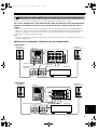
Before using the subwoofer, adjust the subwoofer to obtain the optimum volume and tone balance between the subwoofer
and the main speakers by following the procedures described below.
<YST-SW315>
<YST-SW215>
1 Set the VOLUME control to minimum (0).
2 Turn on the power of all the other components.
3 Make sure that the POWER switch is set to the ON
position, then press the STANDBY/ON button to turn
on the subwoofer.
* The Power indicator lights up in green.
4 Play a source containing low-frequency components
and adjust the amplifier’s volume control to the desired
listening level.
5 Adjust the HIGH CUT control to the position where
the desired response can be obtained.
Normally, set the control to the level a little higher than
the main speaker’s rated minimum reproducible
frequency*.
* The main speaker’s rated minimum reproducible
frequency can be looked up in the speakers’ catalog
or owner’s manual.
6 Increase the volume gradually to adjust the volume
balance between the subwoofer and the main speakers.
Normally, set the control to the level where you can
obtain a little more bass effect than when the
subwoofer is not used. If the desired response cannot
be obtained, adjust the HIGH CUT control and the
VOLUME control again.
7 Set the PHASE switch to the position which gives you
the better bass sound.
Normally, set the switch to the REV (reverse) position.
If the desired response cannot be obtained, set the
switch to the NORM (normal) position.
8 Select “MOVIE” or “MUSIC” according to the played
source.
MOVIE:
When a movie type source is played, the low-
frequency effects are enhanced to allow the listeners
enjoy more powerful sound. (The sound will be thicker
and deeper.)
MUSIC:
When an ordinary music source is played, the
excessive low-frequency components are cut off to
make the sound clearer. (The sound will be lighter and
reproduces the melody line more clearly.)
• Once the volume balance between the subwoofer and
the main speakers is adjusted, you can adjust the
volume of your whole sound system by using the
amplifier’s volume control.
However, if you change the main speakers to others,
you must make this adjustment again.
• For adjusting the VOLUME control, the HIGH CUT
control and the PHASE switch, refer to “Frequency
characteristics” on page 17.
ADJUSTING THE SUBWOOFER BEFORE USE
YST-SW315_215_03.25_tab.fm Page 16 Tuesday, March 25, 2003 4:07 PM

17
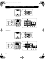
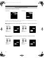
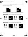
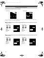
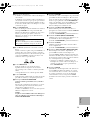
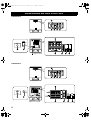
This subwoofer’s frequency characteristics
<YST-SW315> <YST-SW215>
The figures below show the optimum adjustment of each control and the frequency characteristics when this subwoofer
is combined with a typical main speaker system.
■ EX.1 When combined with a 4” or 5” (10 cm or 13 cm) acoustic suspension, 2 way system main
speakers
■ EX.2 When combined with an 8” or 10” (20 cm or 25 cm) acoustic suspension, 2 way system main
speakers
ADJUSTING THE SUBWOOFER BEFORE USE
Frequency characteristics
<YST-SW315>
PHASE :
Set to the
REV(reverse) position
<YST-SW215>
PHASE :
Set to the
REV(reverse) position
<YST-SW315>
PHASE :
Set to the
REV(reverse) position
<YST-SW215>
PHASE :
Set to the
REV(reverse) position
20 50 100 200 500Hz
40
50
60
70
80
90
dB
HIGH CUT 90 Hz
HIGH CUT 140 Hz
HIGH CUT 40 Hz
20 50 100 200 500Hz
40
50
60
70
80
90
dB
HIGH CUT 40 Hz
HIGH CUT 140 Hz
HIGH CUT 90 Hz
20 50 100 200 500Hz
40
50
60
70
80
90
dB
YST-SW315
Main
speaker
20 50 100 200 500Hz
40
50
60
70
80
90
dB
YST-SW215
Main
speaker
20 50 100 200 500Hz
40
50
60
70
80
90
dB
YST-SW315
Main
speaker
20 50 100 200 500Hz
40
50
60
70
80
90
dB
YST-SW215
Main
speaker
YST-SW315_215_03.25_tab.fm Page 17 Tuesday, March 25, 2003 4:07 PM

18
English
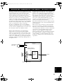
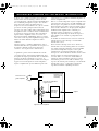
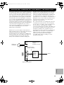
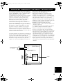
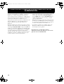
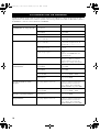
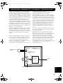
The theory of Yamaha Active Servo Technology has been
based upon two major factors, the Helmholtz resonator and
negative-impedance drive. Active Servo Processing
speakers reproduce the bass frequencies through an “air
woofer”, which is a port or opening in the speaker’s
cabinet. This opening is used instead of, and performs the
functions of, a woofer in a conventionally designed
speaker system. Thus, signals of low amplitude within the
cabinet can, according to the Helmholtz resonance theory,
be outputted from this opening as waves of great amplitude
if the size of the opening and the volume of the cabinet are
in the correct proportion to satisfy a certain ratio.
In order to accomplish this, moreover, the amplitudes
within the cabinet must be both precise and of sufficient
power because these amplitudes must overcome the “load”
presented by the air that exists within the cabinet.
Thus it is this problem that is resolved through the
employment of a new design in which the amplifier
supplies special signals. If the electrical resistance of the
voice coil could be reduced to zero, the movement of the
speaker unit would become linear with respect to signal
voltage. To accomplish this, a special negative-impedance
output-drive amplifier for subtracting output impedance of
the amplifier is used.
By employing negative-impedance drive circuits, the
amplifier is able to generate precise, low-amplitude, low-
frequency waves with superior damping characteristics.
These waves are then radiated from the cabinet opening as
high-amplitude signals. The system can, therefore, by
employing the negative-impedance output drive amplifier
and a speaker cabinet with the Helmholtz resonator,
reproduce an extremely wide range of frequencies with
amazing sound quality and less distortion.
The features described above, then, are combined to be the
fundamental structure of the conventional Yamaha Active
Servo Technology.
Our new Active Servo Technology, Advanced Yamaha
Active Servo Technology, adopted Advanced Negative
Impedance Converter (ANIC) circuits, which allows the
conventional negative impedance converter to dynamically
vary in order to select an optimum value for speaker
impedance variation. With this new ANIC circuits,
Advanced Yamaha Active Servo Technology can provide
more stable performance and improved sound pressure
compared with the conventional Yamaha Active Servo
Technology, resulting in more natural and dynamic bass
reproduction.
ADVANCED YAMAHA ACTIVE SERVO TECHNOLOGY
High-amplitude
bass sound
Port
Cabinet
Advanced Negative-
impedance Converter
Active Servo
Processing
Amplifier
Signals of low amplitude
Air woofer
(Helmholtz resonator)
Signals
YST-SW315_215_03.25_tab.fm Page 18 Tuesday, March 25, 2003 4:07 PM

19
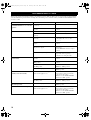
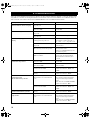
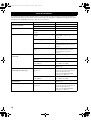
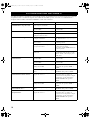
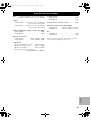
Refer to the chart below when this unit does not function properly. If the problem you are experiencing is not listed below
or if the instructions given below do not help, disconnect the power cord and contact your authorized YAMAHA dealer
or service center.
TROUBLESHOOTING
Problem Cause What to Do
Power is not supplied even though the
STANDBY/ON button is set to the ON
position.
The power plug is not securely
connected.
Connect it securely.
The POWER switch is set to the OFF
position.
Set the POWER switch to the ON
position.
No sound. The volume is set to minimum. Raise the volume up.
Speaker cables are not connected
securely.
Connect them securely.
Sound level is too low. Speaker cables are not connected
correctly.
Connect them correctly, that is L (left) to
L, R (right) to R, “+” to “+” and
“
–” to “–”.
Setting of the PHASE switch is not
proper.
Set the PHASE switch to the other
position.
A source sound with few bass
frequencies is played.
Play a source sound with bass
frequencies.
Set the HIGH CUT control to a higher
position.
It is influenced by standing waves. Reposition the subwoofer or break up
the parallel surface by placing
bookshelves etc. along the walls.
The subwoofer does not turn on
automatically.
The POWER switch is set to the OFF
position.
Set the POWER switch to the ON
position.
The STANDBY/ON button is set to the
OFF position.
Set the STANDBY/ON button to the ON
position.
The AUTO STANDBY switch is set to
the OFF position.
Set the AUTO STANDBY switch to the
“HIGH” or “LOW” position.
The level of input signal is too low. Set the AUTO STANDBY switch to the
“HIGH” position.
The subwoofer does not turn into the
standby mode automatically.
There is an influence of noise generated
from external appliances etc.
Move the subwoofer farther away from
such appliances and/or reposition the
connected speaker cables.
Otherwise, set the AUTO STANDBY
switch to the “OFF” position.
The AUTO STANDBY switch is set to
the OFF position.
Set the AUTO STANDBY switch to the
“HIGH” or “LOW” position.
The subwoofer turns into the standby
mode unexpectedly.
The level of input signal is too low. Set the AUTO STANDBY switch to the
“HIGH” position.
The subwoofer turns on unexpectedly. There is an influence of noise generated
from external appliances etc.
Move the subwoofer farther away from
such appliances and/or reposition the
connected speaker cables.
Otherwise, set the AUTO STANDBY
switch to the “OFF” position.
YST-SW315_215_03.25_tab.fm Page 19 Tuesday, March 25, 2003 4:07 PM
Страница загружается ...
Страница загружается ...
Страница загружается ...
Страница загружается ...
Страница загружается ...
Страница загружается ...
Страница загружается ...
Страница загружается ...
Страница загружается ...
Страница загружается ...
Страница загружается ...
Страница загружается ...
Страница загружается ...
Страница загружается ...
Страница загружается ...
Страница загружается ...
Страница загружается ...
Страница загружается ...
Страница загружается ...
Страница загружается ...
Страница загружается ...
Страница загружается ...
Страница загружается ...
Страница загружается ...
Страница загружается ...
Страница загружается ...
Страница загружается ...
Страница загружается ...
Страница загружается ...
Страница загружается ...
Страница загружается ...
Страница загружается ...
Страница загружается ...
Страница загружается ...
Страница загружается ...
Страница загружается ...
Страница загружается ...
Страница загружается ...
Страница загружается ...
Страница загружается ...
Страница загружается ...
Страница загружается ...
Страница загружается ...
Страница загружается ...
Страница загружается ...
Страница загружается ...
Страница загружается ...
Страница загружается ...
Страница загружается ...
Страница загружается ...
Страница загружается ...
Страница загружается ...
Страница загружается ...
Страница загружается ...
Страница загружается ...
Страница загружается ...
Страница загружается ...
Страница загружается ...
Страница загружается ...
Страница загружается ...
Страница загружается ...
Страница загружается ...
Страница загружается ...
Страница загружается ...
Страница загружается ...
Страница загружается ...
Страница загружается ...
Страница загружается ...
Страница загружается ...
Страница загружается ...
Страница загружается ...
Страница загружается ...
Страница загружается ...
Страница загружается ...
Страница загружается ...
Страница загружается ...
Страница загружается ...
Страница загружается ...
Страница загружается ...
Страница загружается ...
Страница загружается ...
Страница загружается ...
Страница загружается ...
Страница загружается ...
Страница загружается ...
Страница загружается ...
Страница загружается ...
Страница загружается ...
Страница загружается ...
Страница загружается ...
Страница загружается ...
Страница загружается ...
Страница загружается ...
Страница загружается ...
Страница загружается ...
Страница загружается ...
Страница загружается ...
Страница загружается ...
Страница загружается ...
Страница загружается ...
Страница загружается ...
Страница загружается ...
Страница загружается ...
Страница загружается ...
Страница загружается ...
Страница загружается ...
Страница загружается ...
Страница загружается ...
Страница загружается ...
Страница загружается ...
Страница загружается ...
Страница загружается ...
Страница загружается ...
Страница загружается ...
Страница загружается ...
Страница загружается ...
Страница загружается ...
Страница загружается ...
Страница загружается ...
Страница загружается ...
Страница загружается ...
Страница загружается ...
-
 1
1
-
 2
2
-
 3
3
-
 4
4
-
 5
5
-
 6
6
-
 7
7
-
 8
8
-
 9
9
-
 10
10
-
 11
11
-
 12
12
-
 13
13
-
 14
14
-
 15
15
-
 16
16
-
 17
17
-
 18
18
-
 19
19
-
 20
20
-
 21
21
-
 22
22
-
 23
23
-
 24
24
-
 25
25
-
 26
26
-
 27
27
-
 28
28
-
 29
29
-
 30
30
-
 31
31
-
 32
32
-
 33
33
-
 34
34
-
 35
35
-
 36
36
-
 37
37
-
 38
38
-
 39
39
-
 40
40
-
 41
41
-
 42
42
-
 43
43
-
 44
44
-
 45
45
-
 46
46
-
 47
47
-
 48
48
-
 49
49
-
 50
50
-
 51
51
-
 52
52
-
 53
53
-
 54
54
-
 55
55
-
 56
56
-
 57
57
-
 58
58
-
 59
59
-
 60
60
-
 61
61
-
 62
62
-
 63
63
-
 64
64
-
 65
65
-
 66
66
-
 67
67
-
 68
68
-
 69
69
-
 70
70
-
 71
71
-
 72
72
-
 73
73
-
 74
74
-
 75
75
-
 76
76
-
 77
77
-
 78
78
-
 79
79
-
 80
80
-
 81
81
-
 82
82
-
 83
83
-
 84
84
-
 85
85
-
 86
86
-
 87
87
-
 88
88
-
 89
89
-
 90
90
-
 91
91
-
 92
92
-
 93
93
-
 94
94
-
 95
95
-
 96
96
-
 97
97
-
 98
98
-
 99
99
-
 100
100
-
 101
101
-
 102
102
-
 103
103
-
 104
104
-
 105
105
-
 106
106
-
 107
107
-
 108
108
-
 109
109
-
 110
110
-
 111
111
-
 112
112
-
 113
113
-
 114
114
-
 115
115
-
 116
116
-
 117
117
-
 118
118
-
 119
119
-
 120
120
-
 121
121
-
 122
122
-
 123
123
-
 124
124
-
 125
125
-
 126
126
-
 127
127
-
 128
128
-
 129
129
-
 130
130
-
 131
131
-
 132
132
-
 133
133
-
 134
134
-
 135
135
-
 136
136
-
 137
137
-
 138
138
-
 139
139
-
 140
140
-
 141
141
-
 142
142


Yamaha YST-SW215 Инструкция по применению
- Категория
- Сабвуферы
- Тип
- Инструкция по применению
- Это руководство также подходит для
Задайте вопрос, и я найду ответ в документе
Поиск информации в документе стал проще с помощью ИИ
на других языках
- English: Yamaha YST-SW215 Owner's manual
- français: Yamaha YST-SW215 Le manuel du propriétaire
- italiano: Yamaha YST-SW215 Manuale del proprietario
- español: Yamaha YST-SW215 El manual del propietario
- Deutsch: Yamaha YST-SW215 Bedienungsanleitung
- Nederlands: Yamaha YST-SW215 de handleiding
- dansk: Yamaha YST-SW215 Brugervejledning
- svenska: Yamaha YST-SW215 Bruksanvisning
- Türkçe: Yamaha YST-SW215 El kitabı
- suomi: Yamaha YST-SW215 Omistajan opas
- română: Yamaha YST-SW215 Manualul proprietarului
Похожие модели бренда
-
Yamaha NS-SW310 Инструкция по применению
-
Yamaha YST-SW030 Инструкция по применению
-
Yamaha YST-SW030 Инструкция по применению
-
Yamaha YST-FSW100 Инструкция по применению
-
Yamaha YST-SW320 Руководство пользователя
-
-
-
Yamaha YST-SW015 Инструкция по применению
-
-