MSI MS-7C37 v3.1 Инструкция по применению

Категория
Материнские платы
Тип
Инструкция по применению

Это руководство также подходит для

I
Quick Start
Quick Start
Thank you for purchasing the MSI
®
X570-A PRO motherboard. This
Quick Start section provides demonstration diagrams about how to
install your computer. Some of the installations also provide video
demonstrations. Please link to the URL to watch it with the web
browser on your phone or tablet. You may have even link to the URL
by scanning the QR code.
Kurzanleitung
Danke, dass Sie das MSI
®
X570-A PRO Motherboard gewählt
haben. Dieser Abschnitt der Kurzanleitung bietet eine Demo zur
Installation Ihres Computers. Manche Installationen bieten auch
die Videodemonstrationen. Klicken Sie auf die URL, um diese
Videoanleitung mit Ihrem Browser auf Ihrem Handy oder Table
anzusehen. Oder scannen Sie auch den QR Code mit Ihrem Handy,
um die URL zu öffnen.
Présentation rapide
Merci d’avoir choisi la carte mère MSI
®
X570-A PRO. Ce manuel
fournit une rapide présentation avec des illustrations explicatives
qui vous aideront à assembler votre ordinateur. Des tutoriels vidéo
sont disponibles pour certaines étapes. Cliquez sur le lien fourni
pour regarder la vidéo sur votre téléphone ou votre tablette. Vous
pouvez également accéder au lien en scannant le QR code qui lui est
associé.
Быстрый старт
Благодарим вас за покупку материнской платы MSI
®
X570-A PRO.
В этом разделе представлена информация, которая поможет вам
при сборке комьютера. Для некоторых этапов сборки имеются
видеоинструкции. Для просмотра видео, необходимо открыть
соответствующую ссылку в веб-браузере на вашем телефоне или
планшете. Вы также можете выполнить переход по ссылке, путем
сканирования QR-кода.
II
Quick Start
1
2
3
6
4
5
7
8
9
Youtube
https://youtu.be/Xv89nhFk1vc
CPU_FAN1
Installing a Processor/ Installation des Prozessors/ Installer un
processeur/ Установка процессора
III
Quick Start
1
2
3
Important
If you are installing the screw-type CPU heatsink, please follow the figure below to
remove the retention module first and then install the heatsink.
Wenn Sie einen CPU-Kühler mit Schraubenbefestigung einsetzen, folgen Sie bitte
den Anweisungen unten um das Retention-Modul zu entfernen und den Kühler zu
installieren.
Si vous voulez installer un ventirad pour processeur à vis, veuillez suivre les
instructions ci-dessous pour d’abord retirer le module de rétention puis installer le
ventirad.



V
Quick Start
http://youtu.be/DPELIdVNZUI
Youtube
HDD LED
RESET SW
JFP1
HDD LED
HDD LED -
HDD LED +
POWER LED -
POWER LED +
POWER LED
1
2 10
9
+
+
+-
--
-
+
Power LED
HDD LED Reset Switch
Reserved
Power Switch
JFP1
1 HDD LED + 2 Power LED +
3 HDD LED - 4 Power LED -
5 Reset Switch 6 Power Switch
7 Reset Switch 8 Power Switch
9 Reserved 10 No Pin
RESET SW
POWER SW
POWER LED+
POWER LED-
HDD LED
Connecting the Front Panel Header/ Anschließen der
Frontpanel-Stiftleiste/ Connecter un connecteur du panneau
avant/ Подключение разъемов передней панели
VI
Quick Start
BAT1
2
3
1
Installing the Motherboard/ Installation des Motherboards/
Installer la carte mère/ Установка материнской платы
VII
Quick Start
http://youtu.be/gkDYyR_83I4
Youtube
ATX_PWR1
CPU_PWR1
CPU_PWR2
Connecting the Power Connectors/ Stromanschlüsse
anschliessen/ Connecter les câbles du module d’alimentation/
Подключение разъемов питания
VIII
Quick Start
http://youtu.be/RZsMpqxythc
Youtube
1
2
3
4
5
Installing SATA Drives/ Installation der SATA-Laufwerke/
Installer le disque dur SATA/ Установка дисков SATA
XII
Quick Start
NOTE
8
Package contents
Package contents
Please check the contents of your motherboard package. It should contain:
Motherboard X570-A PRO
Cable SATA 6Gb/s Cables 2
Accessories
8.5H M.2 screws 2
Case Badge 1
Product Registration Card 1
Application DVD Driver DVD 1
Documentation Quick Installation Guide 1
Important
If any of the above items are damaged or missing, please contact your retailer.
11
Rear I/O Panel
Audio jacks to headphone and microphone diagram
Audio jacks to stereo speakers diagram
Audio jacks to 7.1-channel speakers diagram
AUDIO INPUT
AUDIO INPUT
Rear Front
Side Center/
Subwoofer
12
Overview of Components
BAT1
JRAINBOW1
JFP1


M2_1
JUSB4
M2_2

JFP2
CPU_FAN1
PUMP_FAN1
PCI_E1
PCI_E2
JBAT1
PCI_E3
PCI_E4
JCI1
PCI_E5
JAUD1
JRGB1
Processor
Socket
CPU_PWR1
CPU_PWR2
JRGB2
JRAINBOW2
JUSB2
JUSB3
JUSB1
JCOM1
JTPM1
SYS_FAN4
SYS_FAN3
SYS_FAN2
SYS_FAN1
ATX_PWR1
DIMMB2
DIMMB1
DIMMA2
DIMMA1
15
Overview of Components
PCI_E1~5: PCIe Expansion Slots
Important
If you install a large and heavy graphics card, you need to use a tool such as MSI
Gaming Series Graphics Card Bolster to support its weight to prevent deformation of
the slot.
For a single PCIe x16 expansion card installation with optimum performance, using
the PCI_E1 slot is recommended.
When adding or removing expansion cards, always turn off the power supply and
unplug the power supply power cable from the power outlet. Read the expansion
card’s documentation to check for any necessary additional hardware or software
changes.
PCIe bandwidth table
Slot Single 2-Way
PCI_E1 (CPU)
@4.0 x16*
or @3.0 x16**
or @3.0 x8***
@4.0 x16*
or @3.0 x16**
or @3.0 x8***
PCI_E2 (PCH) 3.0 x1 3.0 x1
PCI_E3 (PCH)
4.0 x4*
or 3.0 x4**
/
***
@4.0 x4*
or @3.0 x4**
/
***
PCI_E4 (PCH) 3.0 x1 3.0 x1
PCI_E5 (PCH) 3.0 x1 3.0 x1

Ryzen™, ***: for Ryzen™ with Radeon™ Vega Graphics and 2nd Gen AMD Ryzen™ with
Radeon™ Graphics)
Slots 3rd Gen AMD Ryzen™ 2nd Gen AMD Ryzen™
Ryzen™ with Radeon™
Vega Graphics and 2nd
Gen AMD Ryzen™ with
Radeon™ Graphics
PCI_E1 PCIe 4.0 x16 PCIe 3.0 x16 PCIe 3.0 x8
PCI_E2 PCIe 3.0 x1 PCIe 3.0 x1 PCIe 3.0 x1
PCI_E3 PCIe 4.0 x4 PCIe 3.0 x4 PCIe 3.0 x4
PCI_E4 PCIe 3.0 x1 PCIe 3.0 x1 PCIe 3.0 x1
PCI_E5 PCIe 3.0 x1 PCIe 3.0 x1 PCIe 3.0 x1
17
Overview of Components
JFP1, JFP2: Front Panel Connectors
These connectors connect to the switches and LEDs on the front panel.
1
2 10
9
+
+
+-
--
-
+
Power LED
HDD LED Reset Switch
Reserved
Power Switch
JFP1
1 HDD LED + 2 Power LED +
3 HDD LED - 4 Power LED -
5 Reset Switch 6 Power Switch
7 Reset Switch 8 Power Switch
9 Reserved 10 No Pin
1
JFP2
+
+
-
-
Speaker
Buzzer
1 Speaker - 2 Buzzer +
3 Buzzer - 4 Speaker +
SATA1~6: SATA 6Gb/s Connectors
These connectors are SATA 6Gb/s interface ports. Each connector can connect to one
SATA device.
Important
Please do not fold the SATA cable at a 90-degree angle. Data loss may result during
transmission otherwise.
SATA cables have identical plugs on either sides of the cable. However, it is
recommended that the flat connector be connected to the motherboard for space
saving purposes.
SATA5
SATA3
SATA6
SATA4
SATA1
SATA2
18
Overview of Components
24
131
12
ATX_PWR1
1 +3.3V 13 +3.3V
2 +3.3V 14 -12V
3 Ground 15 Ground
4 +5V 16 PS-ON#
5 Ground 17 Ground
6 +5V 18 Ground
7 Ground 19 Ground
8 PWR OK 20 Res
9 5VSB 21 +5V
10 +12V 22 +5V
11 +12V 23 +5V
12 +3.3V 24 Ground
5
4 1
8
CPU_PWR1
1 Ground 5 +12V
2 Ground 6 +12V
3 Ground 7 +12V
4 Ground 8 +12V
Important
Make sure that all the power cables are securely connected to a proper ATX power
supply to ensure stable operation of the motherboard.
CPU_PWR1~2, ATX_PWR1: Power Connectors
These connectors allow you to connect an ATX power supply.
3
2 1
4
CPU_PWR2
1 Ground 3 +12V
2 Ground 4 +12V
20
Overview of Components
JUSB3~4: USB 3.2 Gen1 Connectors
These connectors allow you to connect USB 3.2 Gen1 ports on the front panel.
Important
Note that the Power and Ground pins must be connected correctly to avoid possible
damage.
1
10 11
20
JUSB4
1 10
1120
JUSB3
1 Power 11 USB2.0+
2 USB3_RX_DN 12 USB2.0-
3 USB3_RX_DP 13 Ground
4 Ground 14 USB3_TX_C_DP
5 USB3_TX_C_DN 15 USB3_TX_C_DN
6 USB3_TX_C_DP 16 Ground
7 Ground 17 USB3_RX_DP
8 USB2.0- 18 USB3_RX_DN
9 USB2.0+ 19 Power
10 NC 20 No Pin
JUSB1~2: USB 2.0 Connectors
These connectors allow you to connect USB 2.0 ports on the front panel.
1
2 10
9
1 VCC 2 VCC
3 USB0- 4 USB1-
5 USB0+ 6 USB1+
7 Ground 8 Ground
9 No Pin 10 NC
Important
Note that the VCC and Ground pins must be connected correctly to avoid possible
damage.
In order to recharge your iPad,iPhone and iPod through USB ports, please install
MSI
®
DRAGON CENTER utility.
21
Overview of Components
1
2 10
9
1 DCD 2 SIN
3 SOUT 4 DTR
5 Ground 6 DSR
7 RTS 8 CTS
9 RI 10 No Pin
JCOM1: Serial Port Connector
This connector allows you to connect the optional serial port with bracket.
JAUD1: Front Audio Connector
This connector allows you to connect audio jacks on the front panel.
1
2 10
9
1 MIC L 2 Ground
3 MIC R 4 NC
5 Head Phone R 6 MIC Detection
7 SENSE_SEND 8 No Pin
9 Head Phone L 10 Head Phone Detection
12
Übersicht der Komponenten
BAT1
JRAINBOW1
JFP1


M2_1
JUSB4
M2_2

JFP2
CPU_FAN1
PUMP_FAN1
PCI_E1
PCI_E2
JBAT1
PCI_E3
PCI_E4
JCI1
PCI_E5
JAUD1
JRGB1
Prozessorsockel
CPU_PWR1
CPU_PWR2
JRGB2
JRAINBOW2
JUSB2
JUSB3
JUSB1
JCOM1
JTPM1
SYS_FAN4
SYS_FAN3
SYS_FAN2
SYS_FAN1
ATX_PWR1
DIMMB2
DIMMB1
DIMMA2
DIMMA1
15
Übersicht der Komponenten
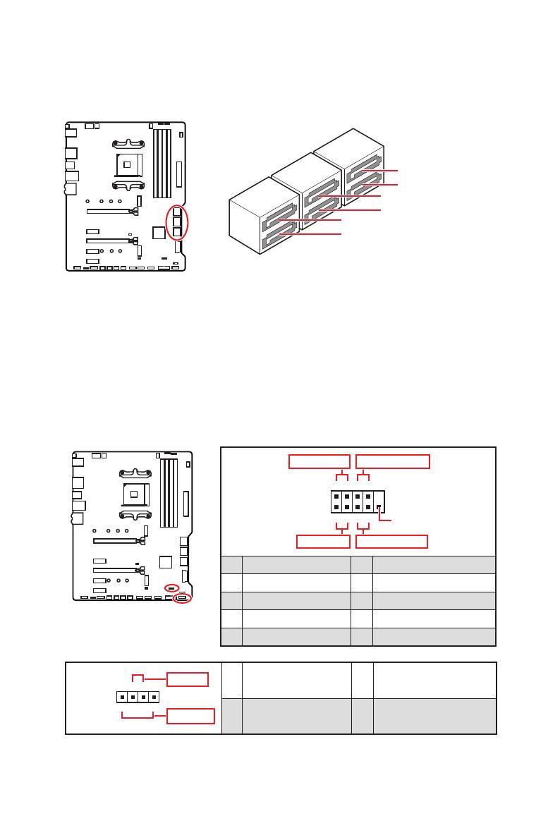
PCI_E1~5: PCIe Erweiterungssteckplätze
Wichtig
Wenn Sie eine große und schwere Grafikkarte einbauen, benötigen Sie einen
Grafikkarten-Stabilisator (Graphics Card Bolster) der das Gewicht trägt und eine
Verformung des Steckplatzes vermeidet.
Für die Installation einer einzelnen PCIe x16 Erweiterungskarte mit optimaler
Leistung, empfehlen wir den PCI_E1 Steckplatz zu verwenden.
Achten Sie darauf, dass Sie den Strom abschalten und das Netzkabel aus der
Steckdose herausziehen, bevor Sie eine Erweiterungskarte installieren oder
entfernen. Lesen Sie bitte auch die Dokumentation der Erweiterungskarte, um
notwendige zusätzliche Hardware oder Software-Änderungen zu überprüfen.
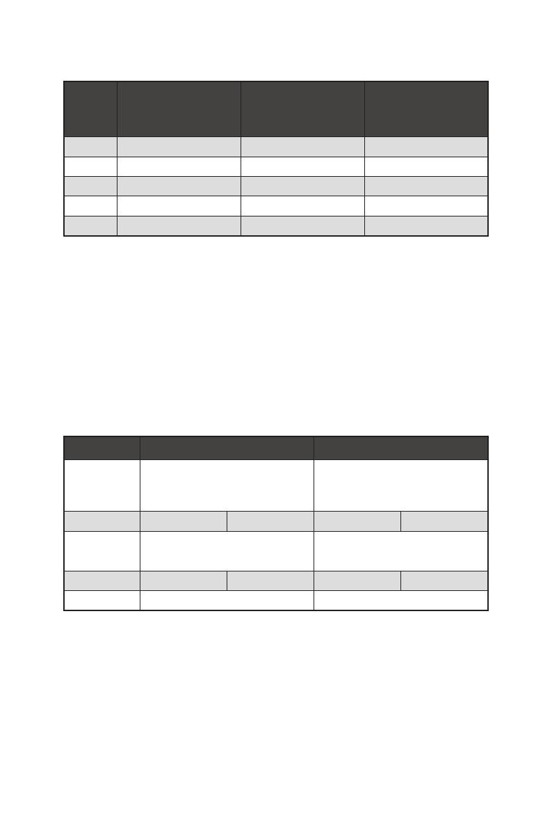
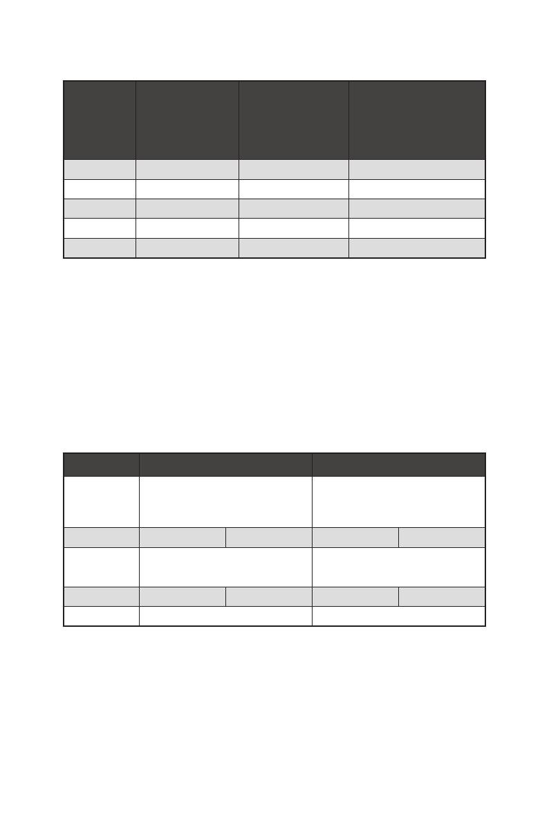
Tabelle der PCIe Bandbreiten
Steckplatz Einzel 2-Wege
PCI_E1 (CPU)
@4.0 x16*
or @3.0 x16**
or @3.0 x8***
@4.0 x16*
or @3.0 x16**
or @3.0 x8***
PCI_E2 (PCH) 3.0 x1 3.0 x1
PCI_E3 (PCH)
4.0 x4*
or 3.0 x4**
/
***
@4.0 x4*
or @3.0 x4**
/
***
PCI_E4 (PCH) 3.0 x1 3.0 x1
PCI_E5 (PCH) 3.0 x1 3.0 x1

der 3. Generation
Prozessoren, **: Für AMD Ryzen
der 2. Generation Prozessoren, ***: Für Ryzen
Prozessoren mit Radeon
Vega Grafikprozessor und AMD Ryzen
der 2. Generation
Prozessoren mit Radeon
Grafikprozessor)
Steckplätze
AMD Ryzen
der
3. Generation
Prozessoren
AMD Ryzen
der
2. Generation
Prozessoren
Ryzen
Prozessoren
mit Radeon
Vega
Grafikprozessor und AMD
Ryzen
der 2. Generation
Prozessoren mit Radeon
Grafikprozessor
PCI_E1 PCIe 4.0 x16 PCIe 3.0 x16 PCIe 3.0 x8
PCI_E2 PCIe 3.0 x1 PCIe 3.0 x1 PCIe 3.0 x1
PCI_E3 PCIe 4.0 x4 PCIe 3.0 x4 PCIe 3.0 x4
PCI_E4 PCIe 3.0 x1 PCIe 3.0 x1 PCIe 3.0 x1
PCI_E5 PCIe 3.0 x1 PCIe 3.0 x1 PCIe 3.0 x1
17
Übersicht der Komponenten
JFP1, JFP2: Frontpanel-Anschlüsse
Diese Anschlüsse verbinden die Schalter und LEDs des Frontpanels.
1
2 10
9
+
+
+-
--
-
+
Power LED
HDD LED Reset Switch
Reserved
Power Switch
JFP1
1 HDD LED + 2 Power LED +
3 HDD LED - 4 Power LED -
5 Reset Switch 6 Power Switch
7 Reset Switch 8 Power Switch
9 Reserved 10 No Pin
1
JFP2
+
+
-
-
Speaker
Buzzer
1 Speaker - 2 Buzzer +
3 Buzzer - 4 Speaker +
SATA1~6: SATA 6Gb/s Anschlüsse
Dieser Anschluss basiert auf der Hochgeschwindigkeitsschnittstelle SATA 6 Gb/s. Pro
Anschluss kann ein SATA Gerät angeschlossen werden.
Wichtig
Knicken Sie das SATA-Kabel nicht in einem 90° Winkel. Datenverlust könnte die
Folge sein.
SATA-Kabel haben identische Stecker an beiden Enden. Es wird empfohlen den
flachen Stecker auf dem Motherboard einstecken.
SATA5
SATA3
SATA6
SATA4
SATA1
SATA2
18
Übersicht der Komponenten
24
131
12
ATX_PWR1
1 +3.3V 13 +3.3V
2 +3.3V 14 -12V
3 Ground 15 Ground
4 +5V 16 PS-ON#
5 Ground 17 Ground
6 +5V 18 Ground
7 Ground 19 Ground
8 PWR OK 20 Res
9 5VSB 21 +5V
10 +12V 22 +5V
11 +12V 23 +5V
12 +3.3V 24 Ground
5
4 1
8
CPU_PWR1
1 Ground 5 +12V
2 Ground 6 +12V
3 Ground 7 +12V
4 Ground 8 +12V
Wichtig
Stellen Sie sicher, dass alle Anschlüsse mit den richtigen Anschlüssen des Netzteils
verbunden sind, um einen stabilen Betrieb der Hauptplatine sicherzustellen.
CPU_PWR1~2, ATX_PWR1: Stromanschlüsse
Mit diesen Anschlüssen verbinden Sie die ATX Stromstecker.
3
2 1
4
CPU_PWR2
1 Ground 3 +12V
2 Ground 4 +12V
  • Page 1 1
  • Page 2 2
  • Page 3 3
  • Page 4 4
  • Page 5 5
  • Page 6 6
  • Page 7 7
  • Page 8 8
  • Page 9 9
  • Page 10 10
  • Page 11 11
  • Page 12 12
  • Page 13 13
  • Page 14 14
  • Page 15 15
  • Page 16 16
  • Page 17 17
  • Page 18 18
  • Page 19 19
  • Page 20 20
  • Page 21 21
  • Page 22 22
  • Page 23 23
  • Page 24 24
  • Page 25 25
  • Page 26 26
  • Page 27 27
  • Page 28 28
  • Page 29 29
  • Page 30 30
  • Page 31 31
  • Page 32 32
  • Page 33 33
  • Page 34 34
  • Page 35 35
  • Page 36 36
  • Page 37 37
  • Page 38 38
  • Page 39 39
  • Page 40 40
  • Page 41 41
  • Page 42 42
  • Page 43 43
  • Page 44 44
  • Page 45 45
  • Page 46 46
  • Page 47 47
  • Page 48 48
  • Page 49 49
  • Page 50 50
  • Page 51 51
  • Page 52 52
  • Page 53 53
  • Page 54 54
  • Page 55 55
  • Page 56 56
  • Page 57 57
  • Page 58 58
  • Page 59 59
  • Page 60 60
  • Page 61 61
  • Page 62 62
  • Page 63 63
  • Page 64 64
  • Page 65 65
  • Page 66 66
  • Page 67 67
  • Page 68 68
  • Page 69 69
  • Page 70 70
  • Page 71 71
  • Page 72 72
  • Page 73 73
  • Page 74 74
  • Page 75 75
  • Page 76 76
  • Page 77 77
  • Page 78 78
  • Page 79 79
  • Page 80 80
  • Page 81 81
  • Page 82 82
  • Page 83 83
  • Page 84 84
  • Page 85 85
  • Page 86 86
  • Page 87 87
  • Page 88 88
  • Page 89 89
  • Page 90 90
  • Page 91 91
  • Page 92 92
  • Page 93 93
  • Page 94 94
  • Page 95 95
  • Page 96 96
  • Page 97 97
  • Page 98 98
  • Page 99 99
  • Page 100 100
  • Page 101 101
  • Page 102 102
  • Page 103 103
  • Page 104 104
  • Page 105 105
  • Page 106 106
  • Page 107 107
  • Page 108 108
  • Page 109 109
  • Page 110 110
  • Page 111 111
  • Page 112 112
  • Page 113 113
  • Page 114 114
  • Page 115 115
  • Page 116 116
  • Page 117 117
  • Page 118 118
  • Page 119 119
  • Page 120 120
  • Page 121 121
  • Page 122 122
  • Page 123 123
  • Page 124 124
  • Page 125 125
  • Page 126 126
  • Page 127 127
  • Page 128 128
  • Page 129 129
  • Page 130 130
  • Page 131 131
  • Page 132 132
  • Page 133 133
  • Page 134 134
  • Page 135 135
  • Page 136 136
  • Page 137 137
  • Page 138 138
  • Page 139 139
  • Page 140 140
  • Page 141 141
  • Page 142 142
  • Page 143 143
  • Page 144 144
  • Page 145 145
  • Page 146 146
  • Page 147 147
  • Page 148 148
  • Page 149 149
  • Page 150 150
  • Page 151 151
  • Page 152 152
  • Page 153 153
  • Page 154 154
  • Page 155 155
  • Page 156 156
  • Page 157 157
  • Page 158 158
  • Page 159 159
  • Page 160 160

MSI MS-7C37 v3.1 Инструкция по применению

Категория
Материнские платы
Тип
Инструкция по применению
Это руководство также подходит для

Задайте вопрос, и я найду ответ в документе

Поиск информации в документе стал проще с помощью ИИ