Tripp Lite Switched Rack PDU Инструкция по применению
- Категория
- Блоки распределения питания (PDUs)
- Тип
- Инструкция по применению

1
Owner’s Manual
PDUMH15NET/PDUMH20NET
Switched Rack PDU
• 120V, 60 Hz AC Input and Output
PDUMH15HVNET/PDUMH20HVNET
Switched Rack PDU
• 208/230V, 50/60 Hz AC Input and Output
Important Safety Instructions 2
Installation 3
Features 6
Technical Support 8
Warranty and Product Registration 8
Español 9
Français 17
Русский 25
PROTECT YOUR INVESTMENT!
Register your product for quicker service
and ultimate peace of mind.
You could also win an
ISOBAR6ULTRA surge protector—
a $100 value!
www.tripplite.com/warranty
1111 W. 35th Street, Chicago, IL 60609 USA • www.tripplite.com/support
Copyright © 2019 Tripp Lite. All rights reserved.
21-03-425-93368A.indb 121-03-425-93368A.indb 1 4/5/2021 2:41:42 PM4/5/2021 2:41:42 PM

2
SAVE THESE INSTRUCTIONS
This manual contains instructions and warnings that should be
followed during the installation, operation, and storage of this product.
Failure to heed these instructions and warnings may affect the product
warranty.
CAUTION Only those who are properly trained or qualified to use this device should
do so. Anyone who is not trained or qualified should not use this device unless it is
under the supervision of someone who is properly trained or qualified to do so.
Children must be supervised to ensure that they do not use the device as a toy.
Never use the device if the cord and plug are damaged; if it is not working properly,
or if it has been dropped or damaged, take it to an authorized service center for
inspection and repair.
If the power cord is damaged, it must be replaced by the manufacturer, its authorized
service agent, or by qualified personnel in order to avoid a danger.
Important Safety Instructions
• The PDU provides the convenience of multiple outlets, but DOES NOT provide surge or line
noise protection for connected equipment.
• The PDU is designed for indoor use only, in a controlled environment, away from excess
moisture, temperature extremes, conductive contaminants, dust or direct sunlight.
• Keep indoor ambient temperature between 32°F and 122°F (0°C and 50°C).
• The PDU must be installed by a qualified technician only.
• Do not attempt to mount the PDU to an insecure or unstable surface.
• Install in accordance with National Electrical Code standards. Be sure to use the proper
overcurrent protection for the installation, in accordance with the plug/equipment rating.
• Connect the PDU to an outlet that is in accordance with your local building codes and that is
adequately protected against excess currents, short circuits and earth faults.
• The electrical outlets supplying power to the equipment should be installed near the
equipment and easily accessible.
• Do not connect the PDU to an ungrounded outlet or to extension cords or adapters that
eliminate the connection to ground.
• Be sure to provide a local disconnect device on any models that are permanently installed
without a plug that is easily accessible.
• Never attempt to install electrical equipment during a thunderstorm.
• Individual equipment connected to the PDU should not draw more current than the individual
PDU’s outlet’s rating.
• The total load connected to the PDU must not exceed the maximum load rating for the PDU.
• Do not attempt to modify the PDU, input plugs or power cables.
• Do not drill into or attempt to open any part of the PDU housing. There are no user-
serviceable parts inside.
• Do not attempt to use the PDU if any part of it becomes damaged.
• Use of this equipment in life support applications where failure of this equipment can
reasonably be expected to cause the failure of the life support equipment or to significantly
affect its safety or effectiveness is not recommended.
21-03-425-93368A.indb 221-03-425-93368A.indb 2 4/5/2021 2:41:42 PM4/5/2021 2:41:42 PM

A
B
A
1-1
C
D
1-2
A
B
C
D
1-3
A
B
C
D
3
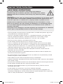
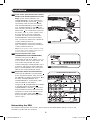
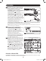
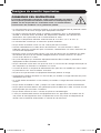
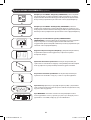
Installation
Mounting the PDU
The PDU supports five primary mounting configurations: 1U Rack, 0U Rack (Vertical), Wall, Under-
Counter and Reduced-Depth.
Note: Regardless of configuration, the user must determine the fitness of hardware and procedures before
mounting. The PDU and included hardware are designed for common rack and rack enclosure types and may
not be appropriate for all applications. Exact mounting configurations may vary. Screws for attaching the
mounting brackets to the PDU are included. Use only the screws supplied by the manufacturer, or their exact
equivalent (#6-32, 3/16" flat head).
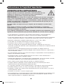
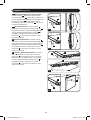
1-1
1U Rack Mounting: Use 3 screws
A
to
attach each of the 2 longer mounting
brackets
B
to the PDU as shown. You
can mount the PDU in a recessed
position by attaching the mounting
brackets so they extend beyond the front
panel of the PDU. Mount the PDU in the
rack by inserting 4 user-supplied screws
C
through the mounting brackets
D
and
into the mounting holes of the rack rails.
1-2
0U Rack Mounting: Use 3 screws
A
to
attach each of the 2 shorter mounting
brackets
B
to the PDU as shown.
Mount the PDU vertically by inserting 2
or more user-supplied screws
C
through
the mounting brackets
D
and into
mounting points in the rack or rack
enclosure.
1-3
Wall Mounting: Use 3 screws
A
to
attach each of the 2 shorter mounting
brackets
B
to the PDU as shown.
Mount the PDU to the wall by inserting
2 or more user-supplied screws
C
through the mounting brackets
D
and
into secure mounting points.
21-03-425-93368A.indb 321-03-425-93368A.indb 3 4/5/2021 2:41:43 PM4/5/2021 2:41:43 PM

A
B
1-5
C
D
2-1
A
B
C
A
B
1-4
C
D
4
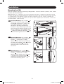
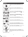
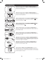
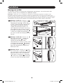
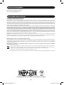
Installation
Connecting the PDU
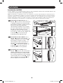
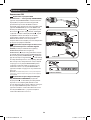
2-1
NEMA Adapter Connection (Optional
- PDUMH20HVNET Only): The
PDUMH20HVNET includes a plug
adapter that adds a NEMA L6-20P plug
to the input power cord. Use this
adapter only if you will be connecting
the PDUMH20HVNET to a NEMA
L6-20R outlet. Insert the IEC 60320
C19 connector
A
of the adapter into
the IEC 60320 C20 connector
B
of the
input power cord. Secure the connection
with the retention bracket
C
by using
the included bolts to fasten the two
halves of the bracket around the
connection as shown.
Caution: To avoid the risk of electric
shock, ensure that the Neutral (L2)
conductor has been identified before
connecting the PDU.
1-4
Under-Counter Mounting: Use 3
screws
A
to attach each of the 2
shorter mounting brackets
B
to the PDU
as shown. Mount the PDU under the
counter by inserting 2 or more user-
supplied screws
C
through the
mounting brackets
D
and into secure
mounting points.
1-5
Reduced-Depth Mounting: Use 3
screws
A
to attach each of the 2
shorter mounting brackets
B
to the PDU
as shown. Mount the PDU to a stable
surface with the outlets facing upward
by inserting 2 or more user-supplied
screws
C
through the mounting
brackets
D
and into secure mounting
points.
21-03-425-93368A.indb 421-03-425-93368A.indb 4 4/5/2021 2:41:44 PM4/5/2021 2:41:44 PM

88
PDUMH15HVNET
PDUMH15NET/PDUMH20NET
88
2-2
PDUMH20HVNET
B
B
A
A
C
C
A
2-3
15
2-4
A
B
C
D
PDUMH20NET
PDUMH15NET
PDUMH15HVNET/PDUMH20HVNET
B
B
D
D
C
C
5
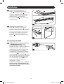
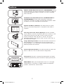
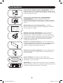
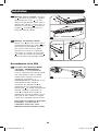
Installation
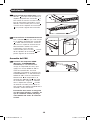
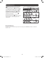
2-2
Input Power Cord Connection (Select
Models with Unattached Power Cords
Only): Insert the IEC 60320 C19
(PDUMH20HVNET) or IEC 60320 C13
(PDUMH15HVNET) connector
A
of the
input power cord into the IEC 60320
C20 (PDUMH20HVNET) or IEC 60320
C14 (PDUMH15HVNET) inlet
B
of the
PDU. Connect the other end of the input
power cord
C
to a compatible source of
AC power, such as a UPS system, PDU
or utility outlet. The PDU should be
provided with over-current protection:
PDUMH20HVNET should be provided
with a maximum 20A branch-rated over-
current protection device;
PDUMH15HVNET should be provided
with a maximum 15A branch-rated over-
current protection device.
Note: The AC power source should not share
a circuit with a heavy electrical load (such as
an air conditioner or refrigerator).
2-3
Connect Input Power Cord
(PDUMH15NET and PDUMH20NET):
Connect the input plug
A
to a
compatible source of AC power, such as
a UPS system, PDU or utility outlet. The
PDU should be provided with over-
current protection: PDUMH15NET with a
maximum 15A branch-rated protection
device. PDUMH20NET with a maximum
20A branch-rated protection device.
2-4
Equipment Power Cord Connection:
Insert the IEC 60320 C14 connectors
A
of the equipment power cords into the
IEC 60320 C13 output receptacles
B
of
the PDU (PDUMH15HVNET and
PDUMH20HVNET). Insert power cords
into the NEMA 5-15R output
receptacles
B
(PDUMH15NET) or NEMA
5-15/20R output receptacles
B
(PDUMH20NET). The LED
C
near each
output receptacle illuminates when the
receptacle is ready to distribute live AC
power. The digital load meter
D
will
display the total connected equipment
load in amps.
Networking the PDU
For network configuration instructions, please refer to the WEBCARDLX owner’s manual (PN
93358E) included with this product.
21-03-425-93368A.indb 521-03-425-93368A.indb 5 4/5/2021 2:41:45 PM4/5/2021 2:41:45 PM

A
B
A
B
6
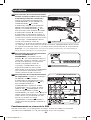
Features
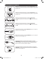
AC Input Power Inlet (Model PDUMH15HVNET): The IEC
60320 C14 inlet connects to the detachable AC Input Power
Cord.
AC Input Power Inlet (Model PDUMH20HVNET): The IEC
60320 C20 inlet connects to the detachable AC Input Power
Cord.
AC Input Power Cord (Model PDUMH15HVNET): The
detachable cord has an IEC 60320 C13 connector
A
and an IEC
60320 C14 connector
B
.
AC Input Power Cord (Model PDUMH20HVNET): The
detachable cord has an IEC 60320 C19 connector
A
and an IEC
60320 C20 connector
B
.
AC Input Power Cord (Model PDUMH15NET): The cord is
permanently attached to the PDU and has a NEMA 5-15P plug.
AC Input Power Cord (Model PDUMH20NET): The cord is
permanently attached to the PDU and has a NEMA L5-20P plug.
AC Input Adapter (Model PDUMH20HVNET): The adapter
converts the AC input power cord to a NEMA L6-20P plug. The
included retention bracket (not shown) secures the connection.
AC Input Adapter (Model PDUMH20NET): The adapter converts
NEMA L5-20P input plugs to NEMA 5-20P input plugs.
NEMA 5-15R Output Receptacles (PDUMH15NET): During
normal operation, the output receptacles distribute AC power to
connected equipment. When an outlet is live, the associated LED
illuminates.
21-03-425-93368A.indb 621-03-425-93368A.indb 6 4/5/2021 2:41:46 PM4/5/2021 2:41:46 PM

RESET
STATUS
CONFIG
7
Features
NEMA 5-15/20R Output Receptacles (PDUMH20NET): During
normal operation, the output receptacles distribute AC power to
connected equipment. When an outlet is live, the associated
LED illuminates.
IEC 60320 C13 Output Receptacles (PDUMH15HVNET &
PDUMH20HVNET): During normal operation, the output
receptacles distribute AC power to connected equipment. When
an outlet is live, the associated LED illuminates.
Digital Load Meter (Ammeter): The total electrical current
drawn by connected equipment is displayed on the meter in
amperes.
C14 Plug-Lock Insert Sleeve (Optional): Use the included
plastic sleeves to secure C13 power cords to C14 inlets. Fit the
sleeve over the end of the cord, making sure the pull-tabs
remain outside the cord and the fit is secure. To unplug
equipment properly, grip both the cord and the insert’s tabs at
the same time and pull.
Longer Mounting Brackets: Use these brackets to mount the
PDU horizontally in a standard rack or rack enclosure. The
mounting depth can be adjusted by attaching the brackets to
different positions on the PDU.
Shorter Mounting Brackets: Use these brackets to mount the
PDU in a 0U rack, wall or under-counter configuration.
Factory Port: The port is reserved for configuration by factory
authorized personnel only. Do not connect anything to the port.
WEBCARDLX: Allows you to operate this PDU as a managed
network device, accessible via SNMP network management
platform, web browser, SSH or Telnet.
21-03-425-93368A.indb 721-03-425-93368A.indb 7 4/5/2021 2:41:47 PM4/5/2021 2:41:47 PM

8
Warranty and Product Registration
LIMITED WARRANTY
Seller warrants this product, if used in accordance with all applicable instructions, to be free from original defects in
material and workmanship for a period of 2 years from the date of initial purchase. If the product should prove
defective in material or workmanship within that period, Seller will repair or replace the product, in its sole discretion.
Service under this Warranty can only be obtained by your delivering or shipping the product (with all shipping or delivery
charges prepaid) to: Tripp Lite, 1111 W. 35th Street, Chicago, IL 60609 USA. Seller will pay return shipping charges.
Visit www.tripplite.com/support before sending any equipment back for repair.
THIS WARRANTY DOES NOT APPLY TO NORMAL WEAR OR TO DAMAGE RESULTING FROM ACCIDENT, MISUSE, ABUSE
OR NEGLECT. SELLER MAKES NO EXPRESS WARRANTIES OTHER THAN THE WARRANTY EXPRESSLY SET FORTH
HEREIN. EXCEPT TO THE EXTENT PROHIBITED BY APPLICABLE LAW, ALL IMPLIED WARRANTIES, INCLUDING ALL
WARRANTIES OF MERCHANTABILITY OR FITNESS, ARE LIMITED IN DURATION TO THE WARRANTY PERIOD SET FORTH
ABOVE; AND THIS WARRANTY EXPRESSLY EXCLUDES ALL INCIDENTAL AND CONSEQUENTIAL DAMAGES. (Some states
do not allow limitations on how long an implied warranty lasts, and some states do not allow the exclusion or limitation
of incidental or consequential damages, so the above limitations or exclusions may not apply to you. This Warranty
gives you specific legal rights, and you may have other rights which vary from jurisdiction to jurisdiction).
WARNING: The individual user should take care to determine prior to use whether this device is suitable, adequate or
safe for the use intended. Since individual applications are subject to great variation, the manufacturer makes no
representation or warranty as to the suitability or fitness of these devices for any specific application.
PRODUCT REGISTRATION
Visit www.tripplite.com/warranty today to register your new Tripp Lite product. You'll be automatically entered into a
drawing for a chance to win a FREE Tripp Lite product!*
* No purchase necessary. Void where prohibited. Some restrictions apply. See website for details.
FCC Notice, Class A
This device complies with part 15 of the FCC Rules. Operation is subject to the following two conditions: (1) This
device may not cause harmful interference, and (2) this device must accept any interference received, including
interference that may cause undesired operation.
Note: This equipment has been tested and found to comply with the limits for a Class A digital device, pursuant to
part 15 of the FCC Rules. These limits are designed to provide reasonable protection against harmful interference
when the equipment is operated in a commercial environment. This equipment generates, uses, and can radiate radio
frequency energy and, if not installed and used in accordance with the instruction manual, may cause harmful
interference to radio communications. Operation of this equipment in a residential area is likely to cause harmful
interference in which case the user will be required to correct the interference at his own expense. The user must use
shielded cables and connectors with this equipment. Any changes or modifications to this equipment not expressly
approved by Tripp Lite could void the user’s authority to operate this equipment.
Regulatory Compliance Identification Numbers
For the purpose of regulatory compliance certifications and identification, your Tripp Lite product has been assigned a
unique series number. The series number can be found on the product nameplate label, along with all required
approval markings and information. When requesting compliance information for this product, always refer to the series
number. The series number should not be confused with the marking name or model number of the product.
WEEE Compliance Information for Tripp Lite Customers and Recyclers (European Union)
Under the Waste Electrical and Electronic Equipment (WEEE) Directive and implementing regulations, when
customers buy new electrical and electronic equipment from Tripp Lite they are entitled to:
• Send old equipment for recycling on a one-for-one, like-for-like basis (this varies depending on the country)
• Send the new equipment back for recycling when this ultimately becomes waste
Tripp Lite has a policy of continuous improvement. Specifications are subject to change without notice.
Technical Support
Website: www.tripplite.com/support
E-mail: [email protected]
1111 W. 35th Street, Chicago, IL 60609 USA • www.tripplite.com/support
21-03-425 • 93-368A_RevE
21-03-425-93368A.indb 821-03-425-93368A.indb 8 4/5/2021 2:41:47 PM4/5/2021 2:41:47 PM

9
Manual del Propietario
PDUMH15NET / PDUMH20NET
PDU Controlable para Rack
• Entrada y Salida de CA 120V, 60Hz
PDUMH15HVNET / PDUMH20HVNET
PDU Controlable para Rack
• Entrada y Salida de CA 208V / 230V, 50/60Hz
Instrucciones de Seguridad Importantes 10
Instalación 11
Características 14
Soporte Técnico 16
Garantía 16
English 1
Français 17
Русский 25
1111 W. 35th Street, Chicago, IL 60609 EE. UU. • www.tripplite.com/support
Copyright © 2019 Tripp Lite. Todos los derechos reservados.
21-03-425-93368A.indb 921-03-425-93368A.indb 9 4/5/2021 2:41:48 PM4/5/2021 2:41:48 PM

10
CONSERVE ESTAS INSTRUCCIONES
Este manual contiene instrucciones y advertencias que deben
seguirse durante la instalación, operación y almacenamiento de este
producto. La omisión en la observancia de estas instrucciones y
advertencias puede afectar la garantía del producto.
PRECAUCION Este aparato no se destina para utilizarse por personas (incluyendo
niños), cuyas capacidades fisicas, sensoriales o mentales sean diferentes o estén
reducidas, o carezcan de experiencia o conocimiento, a menos que dichas personas
reciban una supervisión o capacitación para el funcionamiento del aparato por una
persona responsable de su seguridad.
Los ninos deben de supervisarse para asegurar que no empleen el aparato como
juguete.
Nunca utilize el aparato si el cable y la clavija están dañados; si no funciona
correctamente o si se ha caido o dañado, llévelo a un centro de servicio autorizado
para que lo examinen y lo reparen.
Si el cordon de alimentación es dañado, éste debe sustituirse por el fabricante, por su
agente de servicio autorizado o por personal calificado con el fin de evitar un peligro.
Instrucciones de Seguridad Importantes
• El PDU proporciona la conveniencia de múltiples tomacorrientes, pero NO proporciona
protección contra sobretensión o ruido en la línea para los equipos conectados.
• El PDU está diseñada solo para uso en interiores en un entorno controlado lejos de humedad
excesiva, temperaturas extremas, contaminantes conductivos, polvo o luz del sol directa.
• Mantiene la temperatura ambiente interior entre 32°F y 122°F (0°C y 50°C).
• El PDU debe ser instalado solamente por un técnico calificado.
• No intente instalar el PDU en una superficie inestable o no segura.
• Instale de acuerdo con los reglamentos eléctricos locales. Asegúrese de usar para la
instalación la protección adecuada contra sobrecorriente, de acuerdo con la especificación de
la clavija o del equipo.
• Conecte el PDU a un tomacorriente que esté de acuerdo a los códigos locales de
construcción y que esté correctamente protegido contra corrientes excesivas, cortocircuitos y
fallas de conexión a tierra.
• Los tomacorrientes eléctricos que suministran energía al equipo deben instalarse próximos al
equipo y ser fácilmente accesibles.
• No conecte El PDU a un toma corriente que no esté a tierra o cables de extensión o
adaptadores que eliminen la conexión a tierra.
• Asegúrese de proporcionar un dispositivo local de desconexión, que sea fácilmente accesible,
en cualquier modelo que esté instalado permanentemente sin una clavija.
• Nunca intente instalar equipos eléctricos durante una tormenta eléctrica.
• El equipo individual conectado al PDU no debe consumir más corriente que la de la
especificación de cada tomacorriente individual del PDU.
• La carga total conectada al PDU no debe exceder la capacidad de carga máxima del PDU.
• No intente modificar el PDU, las clavijas de entrada o los cables de alimentación.
• No perfore ni intente abrir ninguna parte del gabinete del PDU. No tiene partes a las que el
usuario pueda dar servicio.
• No intente usar el PDU si se daña cualquier parte.
• No se recomienda el uso de este equipo en aplicaciones de soporte de vida en donde la falla
de este equipo pueda consecuentemente causar la falla del equipo de soporte de vida o
afectar significativamente su seguridad o efectividad.
21-03-425-93368A.indb 1021-03-425-93368A.indb 10 4/5/2021 2:41:48 PM4/5/2021 2:41:48 PM

A
B
A
1-1
C
D
1-2
A
B
C
D
1-3
A
B
C
D
11
Instalación
Instalación del PDU
El PDU soporta cinco configuraciones primarias de instalación: Rack de 1U, Rack 0U (vertical), en
la Pared, Bajo el Mostrador y Profundidad Reducida
Nota: Sin importar la configuración, antes de la instalación, el usuario debe determinar la adecuación de los
accesorios y procedimientos. El PDU y los accesorios incluidos están diseñados para tipos comunes de racks y
gabinetes y pueden no ser apropiados para todas las aplicaciones. Las configuraciones de instalación exactas
pueden variar. Están incluidos los tornillos para fijar los soportes para instalación al PDU. Use solamente los
tornillos suministrados por el fabricante o su equivalente exacto (#6-32, cabeza plana de 3/16”).
1-1
Instalación en Rack de 1U: Use 3
tornillos
A
para instalar cada uno de los
2 soportes grandes de instalación
B
al
PDU como se muestra. Puede instalar el
PDU en una posición empotrada
adjuntando los soportes de instalación
para que sobresalga de la parte frontal
del PDU. Instale el PDU en el rack
insertando 4 tornillos suministrados por
el usuario
C
a través de los soportes de
instalación
D
y en los orificios de
instalación de los rieles del rack.
1-2
Instalación en 0U de Rack: Use 3
tornillos
A
para fijar cada uno de los 2
soportes pequeños de instalación
B
al
PDU como se muestra. Instale
verticalmente el PDU insertando 2 o
más tornillos suministrados por el
usuario
C
a través de los soportes de
instalación
D
y en los puntos de
instalación en el rack o gabinete.
1-3
Instalación en la Pared: Use 3
tornillos
A
para fijar cada uno de los 2
soportes pequeños de instalación
B
al
PDU como se muestra. Instale el PDU
en la pared insertando 2 o más tornillos
suministrados por el usuario
C
a través
de los soportes de instalación
D
y en
puntos seguros de instalación.
21-03-425-93368A.indb 1121-03-425-93368A.indb 11 4/5/2021 2:41:48 PM4/5/2021 2:41:48 PM

A
B
1-5
C
D
2-1
A
B
C
A
B
1-4
C
D
12
Instalación
Conexión del PDU
2-1
Conexión de Adaptador NEMA
(Opcional - PDUMH20HVNET
Solamente): El PDUMH20HVNET
incluye un adaptador de clavija que
agrega una clavija NEMA L6-20P al
cable de alimentación. Use este
adaptador únicamente si conectará el
PDUMH20HVNET a un tomacorrientes
NEMA L6-20R. Insert el conector IEC
60320 C19
A
del adaptador en el
conector IEC 60320 C20
B
del cable
de alimentación. Asegure la conexión
con el soporte de sujeción
C
usando
los tornillos incluidos para sujetar las
dos mitades del soporte alrededor de la
conexión, como se muestra.
Precaución: Para evitar el riesgo de
una descarga eléctrica, asegúres de
que el conductor neutro (L2) haya
sido identificado antes de conectar
el PDU.
1-4
Instalación Bajo el Mostrador: Use 3
tornillos
A
para fijar cada uno de los 2
soportes pequeños de instalación
B
al
PDU como se muestra. Instale el PDU
bajo el mostrador insertando 2 o más
tornillos suministrados por el usuario
C
a través de los soportes de instalación
D
y en puntos seguros de instalación.
1-5
Instalación de Profundidad Reducida:
Use 3 tornillos
A
para fijar cada uno de
los 2 soportes pequeños de instalación
B
al PDU como se muestra. Instale el
PDU en una superficie estable con los
tomacorrientes viendo hacia arriba
insertando 2 o más tornillos
suministrados por el usuario
C
a través
de los soportes de instalación
D
y en
puntos seguros de instalación.
21-03-425-93368A.indb 1221-03-425-93368A.indb 12 4/5/2021 2:41:49 PM4/5/2021 2:41:49 PM

88
PDUMH15HVNET
PDUMH15NET/PDUMH20NET
88
2-2
PDUMH20HVNET
B
B
A
A
C
C
A
2-3
15
2-4
A
B
C
D
PDUMH20NET
PDUMH15NET
PDUMH15HVNET/PDUMH20HVNET
B
B
D
D
C
C
13
Instalación
2-2
Conexión del Cable de Alimentación de
Entrada (Modelos Selectos con Cables
de Alimentación no Conectados
Solamente): Inserte el conector IEC 60320
C19 (PDUMH20HVNET) o IEC 60320 C13
(PDUMH15HVNET)
A
del cable de
alimentación en la entrada IEC 60320 C20
(PDUMH20HVNET) o IEC 60320 C14
(PDUMH15HVNET)
B
del PDU. Conecte el
otro extremo del cable de alimentación
C
a
una fuente compatible de energía de CA
como un sistema UPS, PDU o tomacorriente
de la red pública. El PDU debe ser proveído
con protección de sobrecorriente: El
PDUMH20HVNET debe estar provisto con
un dispositivo de protección de
sobrecorriente de especificación de ramal
Conexión a Red del PDU
Para obtener instrucciones de configuración de red, consulte el manual del usuario de la tarjeta
WEBCARDLX (PN 93358E) incluido con este producto.
de 20A máximo; El PDUMH15HVNET debe estar provisto con un dispositivo de protección
de sobrecorriente con especificación de ramal de 15A máximo.
Nota: La fuente de energía de CA no debe compartir un circuito con una carga eléctrica pesada (como
un aire acondicionado o refrigerador).
2-3
Conecte el Cable de Alimentación
(PDUMH15NET y PDUMH20NET): Conecte
la clavija de entrada
A
a una fuente
compatible de energía de CA, como un
sistema UPS, PDU o tomacorriente de
energía de la red pública. El PDU debe estar
equipado con protección contra
sobrecorriente; PDUMH15NET con un
dispositivo de protección especificado para
15A máximo por ramal. PDUMH20NET con
un dispositivo de protección especificado
para 20A máximo por ramal.
2-4
Conexión de Cable de Alimentación del
Equipo: Inserte los conectores IEC 60320
C14
A
de los cables de alimentación de los
equipos en los tomacorrientes IEC 60320
C13
B
del PDU (PDUMH15HVNET y
PDUMH20HVNET). Inserte los cables de
alimentación en los tomacorrientes NEMA
5-15R
B
(PDUMH15NET) o tomacorrientes
NEMA 5-15/20R
B
(PDUMH20NET). El LED
C
junto a cada tomacorrientes se enciende
cuando el tomacorriente está listo para
distribuir energía viva de CA. El medidor
digital de carga
D
mostrará la carga total
del equipo conectado en amperes.
21-03-425-93368A.indb 1321-03-425-93368A.indb 13 4/5/2021 2:41:50 PM4/5/2021 2:41:50 PM

A
B
A
B
14
Características
Entrada de Energía de CA (Modelo PDUMH15HVNET): La
entrada IEC 60320 C14 se conecta al Cable de Alimentación de
Entrada de CA desprendible.
Entrada de Energía de CA (Modelo PDUMH20HVNET): La
entrada IEC 60320 C20 se conecta al Cable de Alimentación de
Entrada de CA desprendible.
Cable de Alimentación de CA (Modelo PDUMH15HVNET): El
cable desprendible tiene un conector IEC 60320 C13
A
y un
conector IEC 60320 C14
B
.
Cable de Alimentación de CA (Modelo PDUMH20HVNET): El
cable desprendible tiene un conector IEC 60320 C19
A
y un
conector IEC 60320 C20
B
.
Cable de Alimentación de CA (Modelo PDUMH15NET): El
cable está conectado de forma permanente al PDU y tiene una
clavija NEMA 5-15P.
Cable de Alimentación de CA (Modelo PDUMH20NET): El
cable está conectado de forma permanente al PDU y tiene una
clavija NEMA L5-20P.
Adaptador de Entrada de CA (Modelo PDUMH20HVNET): El
adaptador convierte el Cable de Alimentación de Entrada de CA
a una clavija NEMA L6-20P. El soporte de sujeción incluido (no
se muestra) asegura la conexión.
Adaptador de Entrada de CA (Modelo PDUMH20NET): El
adaptador convierte las clavijas de entrada NEMA L5-20P a
clavijas de entrada NEMA 5-20P.
Tomacorrientes NEMA 5-15R (PDUMH15NET): Durante la
operación normal, los tomacorrientes distribuyen energía de CA
al equipo conectado. Cuando un tomacorrientes está encendido,
el LED asociado se ilumina.
21-03-425-93368A.indb 1421-03-425-93368A.indb 14 4/5/2021 2:41:51 PM4/5/2021 2:41:51 PM

RESET
STATUS
CONFIG
15
Características
Tomacorrientes NEMA 5-15/20R (PDUMH20NET): Durante la
operación normal, los tomacorrientes distribuyen energía de CA
al equipo conectado. Cuando un tomacorrientes está encendido,
el LED asociado se ilumina.
Tomacorrientes IEC 60320 C13 (PDUMH15HVNET y
PDUMH20HVNET): Durante la operación normal, los
tomacorrientes distribuyen energía de CA al equipo conectado.
Cuando un tomacorrientes está encendido, el LED asociado se
ilumina.
Medidor Digital de Carga (Amperímetro): La corriente
eléctrica total tomada por los equipos conectados se muestra
en el medidor en amperes.
Manguito de Clavija C14 (Opcional): Use los manguitos
plásticos C14 incluidos para asegurar las clavijas a los
tomacorrientes. Acople el manguito a la clavija asegurándose
que las pestañas de tiro permanezcan fuera de la clavija y que
la sujeción sea segura. Para desenchufar correctamente el
equipo, use las pestañas de tiro para retirar la clavija y el
manguito del tomacorriente.
Soportes de Instalación Grandes: Use estos soportes para
instalar horizontalmente el PDU en un rack o gabinete estándar.
La profundidad de instalación puede ajustarse fijando los
soportes a diferentes posiciones en el PDU.
Soportes de Instalación Pequeños: Use estos soportes para
instalar el PDU en una configuración de rack de 0U, pared o
bajo el mostrador.
Puerto de Fábrica: El puerto está reservado para la
configuración solo por parte de personal autorizado de fábrica.
No conecte nada en el puerto.
WEBCARDLX: Le permite operar este PDU como un dispositivo
de red, accesible a través de la plataforma de administración de
red SNMP, navegador de Internet, SSH o Telnet.
21-03-425-93368A.indb 1521-03-425-93368A.indb 15 4/5/2021 2:41:51 PM4/5/2021 2:41:51 PM

16
Garantía
GARANTÍA LIMITADA
El vendedor garantiza este producto, si se usa de acuerdo con todas las instrucciones aplicables, de que está libre de
defectos en material y mano de obra por un período de 2 años a partir de la fecha de compra inicial. Si el producto
resulta defectuoso en material o mano de obra dentro de ese período, el vendedor reparará o reemplazará el producto
a su entera discreción. El servicio bajo esta garantía sólo puede obtenerse enviando o embarcando el producto (con
todos los cargos de envío o embarque prepagados) a: Tripp Lite, 1111 W. 35th Street, Chicago, IL 60609 EE UU. El
vendedor reembolsará los cargos de embarque. Antes de devolver cualquier equipo para reparación, visite www.
tripplite.com/support.
ESTA GARANTÍA NO APLICA AL DESGASTE NORMAL O A DAÑOS RESULTANTES DE ACCIDENTES, MAL USO, ABUSO O
NEGLIGENCIA. EL VENDEDOR NO OTORGA GARANTÍAS EXPRESAS DISTINTAS DE LA ESTIPULADA EN EL PRESENTE.
SALVO EN LA MEDIDA EN QUE LO PROHÍBAN LAS LEYES APLICABLES, TODAS LAS GARANTÍAS IMPLÍCITAS,
INCLUYENDO TODAS LAS GARANTÍAS DE COMERCIALIZACIÓN O IDONEIDAD, ESTÁN LIMITADAS EN DURACIÓN AL
PERÍODO DE GARANTÍA ESTABLECIDO; ASIMISMO, ESTA GARANTÍA EXCLUYE EXPRESAMENTE TODOS LOS DAÑOS
INCIDENTALES E INDIRECTOS. (Algunos estados no permiten limitaciones en cuanto dura una garantía y algunos
estados no permiten la exclusión de limitación de daños incidentales o consecuenciales, de modo que las limitaciones
anteriores pueden no aplicar para usted. Esta garantía le otorga derechos legales específicos y usted puede tener
otros derechos que pueden variar de una jurisdicción a otra).
ADVERTENCIA: Antes de usarlo, cada usuario debe debe tener cuidado al determinar si este dispositivo es adecuado o
seguro para el uso previsto. Ya que las aplicaciones individuales están sujetas a gran variación, el fabricante no
garantiza la adecuación de estos dispositivos para alguna aplicación específica.
Números de Identificación de Conformidad Regulatoria
Para el propósito de certificaciones e identificación de conformidad con las normas, su producto Tripp Lite ha recibido
un número de serie exclusivo. El número de serie puede encontrarse en la etiqueta de placa de identificación, junto
con todas las marcas e información requeridas de aprobación. Al solicitar información de conformidad para este
producto, refiera siempre el número de serie. El número de serie no debe confundirse con el nombre de la marca o el
número de modelo del producto.
Información de Cumplimiento con WEEE por los Clientes y Recicladores de Tripp Lite (Unión Europea)
Bajo la Directiva de Desechos de Equipos Eléctricos y Electrónicos (WEEE) [Waste Electrical and Electronic
Equipment] y regulaciones aplicables, cuando los clientes adquieren un nuevo equipo eléctrico y electrónico
de Tripp Lite están obligados a:
• Enviar el equipo viejo a reciclado en una base de uno por uno, equivalente por equivalente (esto varía de un
país a otro)
• Regrese el equipo nuevo para reciclado una vez que finalmente sea un desecho
Tripp Lite tiene una política de mejora continua. Las especificaciones están sujetas a cambio sin previo aviso.
Soporte Técnico
Website: www.tripplite.com/support
Correo Electrónico: [email protected]
1111 W. 35th Street, Chicago, IL 60609 USA • www.tripplite.com/support
21-03-425 • 93-368A_RevE
21-03-425-93368A.indb 1621-03-425-93368A.indb 16 4/5/2021 2:41:51 PM4/5/2021 2:41:51 PM

17
Manuel de l'utilisateur
PDUMH15NET/PDUMH20NET
PDU en bâti commutée
• Entrée et sortie CA, 120 V, 60 Hz
PDUMH15HVNET/PDUMH20HVNET
PDU en bâti commutée
• Entrée et sortie CA, 208/230 V, 50/60 Hz
Consignes de sécurité importantes 18
Installation 19
Caractéristiques 22
Soutien technique 24
Garantie 24
English 1
Español 9
Русский 25
1111 W. 35th Street, Chicago, IL 60609 USA • www.tripplite.com/support
Droits d'auteur © 2019 Tripp Lite. Tous droits réservés.
21-03-425-93368A.indb 1721-03-425-93368A.indb 17 4/5/2021 2:41:52 PM4/5/2021 2:41:52 PM

18
CONSERVEZ CES INSTRUCTIONS
Ce manuel contient des instructions et des avertissements qui doivent
être respectés pendant l'installation, l'utilisation et l'entreposage de ce
produit. Le non-respect de ces instructions et de ces avertissements
pourrait avoir une incidence sur la garantie du produit.
Consignes de sécurité importantes
• La PDU fournit des prises multiples pratiques, mais elle ne FOURNIT PAS de protection contre
les surtensions ou les bruits de ligne pour l'équipement connecté.
• La PDU est conçue pour être utilisée à l'intérieur uniquement, dans un environnement
contrôlé, à l'écart de l'excès d'humidité, des températures extrêmes, des contaminants
conducteurs, de la poussière et de la lumière directe du soleil.
• Maintenir la température intérieure ambiante entre 0 °C et 50 °C (32 °F et 122 °F).
• La PDU doit être installée par un technicien qualifié seulement.
• Ne pas tenter de monter la PDU sur une surface précaire ou instable.
• Installer conformément aux codes locaux de l'électricité. S'assurer d'utiliser la bonne
protection contre les surintensités pour l'installation, conformément aux valeurs nominales de
la fiche et de l'équipement.
• Branchez la PDU à une prise de courant à une prise de courant qui est conforme aux codes
de bâtiment locaux et qui est dûment protégée contre les courants excessifs, les courts-
circuits et les défauts à la terre.
• Les prises électriques qui alimentent l'équipement doivent être installées à proximité de
l'équipement et être facilement accessibles.
• Ne pas connecter la PDU dans une prise non mise à la masse ou des rallonges électriques ou
des adaptateurs qui éliminent la connexion à la masse.
• S'assurer de fournir un dispositif de déconnexion local pour tous les modèles qui sont installés
en permanence sans fiche facilement accessible.
• Ne jamais essayer d'installer un équipement électrique pendant un orage.
• L'équipement individuel connecté à la PDU ne doit pas excéder la charge nominale des prises
individuelles de la PDU.
• La charge totale connectée à la PDU ne doit pas excéder la charge nominale maximum pour
la PDU.
• Ne pas tenter de modifier la PDU, y compris les fiches d'entrée et les câbles d'alimentation.
• Ne pas percer ou tenter d'ouvrir une quelconque partie du boîtier de la PDU. Il n'existe aucune
pièce réparable par l'utilisateur à l'intérieur.
• Ne pas tenter d'utiliser la PDU si une de ses pièces est endommagée.
• Il n'est pas recommandé d'utiliser cet équipement dans les applications de soutien vital où
une panne de cet équipement serait susceptible de causer une panne de l'équipement de
soutien vital ou d'affecter sérieusement sa sécurité ou son efficacité.
21-03-425-93368A.indb 1821-03-425-93368A.indb 18 4/5/2021 2:41:52 PM4/5/2021 2:41:52 PM

A
B
A
1-1
C
D
1-2
A
B
C
D
1-3
A
B
C
D
19
Installation
Montage de la PDU
La PDU peut accueillir cinq principales configurations de montage : 1U en bâti, 0U en bâti
(vertical), murale, sous le comptoir et à profondeur réduite.
Remarque : Quelle que soit la configuration, l'utilisateur doit déterminer l'aptitude du matériel et des
procédures avant de procéder au montage. La PDU et le matériel inclus sont conçus pour les bâtis et les
boîtiers pour bâtis communs et peuvent ne pas être appropriés pour toutes les applications. Les configurations
de montage exactes peuvent varier. Les vis pour fixer les supports de montage à la PDU sont incluses. Utiliser
uniquement les vis fournies par le fabricant ou leur équivalent exact (no 6-32, 3/16 po à tête plate).
1-1
Montage en bâti 1U : Utiliser 3 vis
A
pour fixer chacun des 2 supports de
montage plus longs
B
à la PDU comme
illustré. La PDU peut être montée dans
une position encastrée en fixant les
supports de montage de façon à ce
qu'ils dépassent le panneau avant de la
PDU. Monter la PDU au bâti en insérant
les quatre vis fournies par l'utilisateur
C
à travers les supports de montage
D
,
puis dans les trous de montage des rails
du bâti.
1-2
Montage en bâti 0U : Utiliser 3 vis
A
pour fixer chacun des 2 supports de
montage plus courts
B
à la PDU
comme illustré. Monter la PDU
verticalement en insérant au moins deux
vis fournies par l'utilisateur
C
à travers
les supports de montage
D
et dans les
points de montage dans le bâti ou le
boîtier pour bâti.
1-3
Montage mural : Utiliser 3 vis
A
pour
fixer chacun des 2 supports de montage
plus courts
B
à la PDU comme illustré.
Monter la PDU au mur en insérant au
moins deux vis fournies par l'utilisateur
C
à travers les supports
D
de montage
et dans les points de montage solides.
21-03-425-93368A.indb 1921-03-425-93368A.indb 19 4/5/2021 2:41:53 PM4/5/2021 2:41:53 PM

A
B
1-5
C
D
2-1
A
B
C
A
B
1-4
C
D
20
Installation
Raccordement de la PDU
2-1
Connexion de l'adaptateur NEMA
(facultatif - PDUMH20HVNET
seulement) : La PDUMH20HVNET
inclut un adaptateur de fiche qui ajoute
une fiche NEMA L6-20P au cordon
d'alimentation d'entrée. Utiliser cet
adaptateur uniquement si la
PDUMH20HVNET est connectée à une
prise NEMA L6-20R. Insérer le
connecteur IEC 60320 C19
A
de
l'adaptateur dans le connecteur IEC
60320 C20
B
du cordon d'alimentation
d'entrée. Maintenir la connexion en
place
C
au moyen d'un support de
rétention en utilisant les boulons inclus
pour fixer les deux moitiés du support
autour de la connexion comme illustré.
Pour éviter les risques de décharges
électriques, s'assurer que le
conducteur neutre (L2) a été
identifié avant de raccorder la PDU.
1-4
Montage sous le comptoir : Utiliser 3
vis
A
pour fixer chacun des 2 supports
de montage plus courts
B
à la PDU
comme illustré. Monter la PDU sous le
comptoir en insérant au moins deux vis
fournies par l'utilisateur
C
à travers les
supports
D
de montage et dans les
points de montage solides.
1-5
Montage à profondeur réduite :
Utiliser 3 vis
A
pour fixer chacun des 2
supports de montage plus courts
B
à la
PDU comme illustré. Monter la PDU à
une surface stable avec les sorties
tournées vers le haut en insérant au
moins deux vis fournies par l'utilisateur
C
à travers les supports de montage
D
et dans les points de montage solides.
21-03-425-93368A.indb 2021-03-425-93368A.indb 20 4/5/2021 2:41:53 PM4/5/2021 2:41:53 PM
Страница загружается ...
Страница загружается ...
Страница загружается ...
Страница загружается ...
Страница загружается ...
Страница загружается ...
Страница загружается ...
Страница загружается ...
Страница загружается ...
Страница загружается ...
Страница загружается ...
Страница загружается ...
-
 1
1
-
 2
2
-
 3
3
-
 4
4
-
 5
5
-
 6
6
-
 7
7
-
 8
8
-
 9
9
-
 10
10
-
 11
11
-
 12
12
-
 13
13
-
 14
14
-
 15
15
-
 16
16
-
 17
17
-
 18
18
-
 19
19
-
 20
20
-
 21
21
-
 22
22
-
 23
23
-
 24
24
-
 25
25
-
 26
26
-
 27
27
-
 28
28
-
 29
29
-
 30
30
-
 31
31
-
 32
32


Tripp Lite Switched Rack PDU Инструкция по применению
- Категория
- Блоки распределения питания (PDUs)
- Тип
- Инструкция по применению
Задайте вопрос, и я найду ответ в документе
Поиск информации в документе стал проще с помощью ИИ
на других языках
Похожие модели бренда
-
Tripp Lite Switched Rack PDU Инструкция по применению
-
-
-
Tripp Lite Metered Rack PDU Инструкция по применению
-
Tripp Lite PDUMNH20HV High Voltage Monitored Rack PDUs Инструкция по применению
-
Tripp Lite 12U Desktop 2-Post Open Frame Rack Инструкция по применению
-
-
-
-
Tripp Lite Metered Rack PDU Инструкция по применению

