Yamaha RX-V2065 Инструкция по применению
- Категория
- Аудио-видео ресиверы
- Тип
- Инструкция по применению

© 2009 Yamaha Corporation All rights reserved.
Printed in Malaysia WS30780
RX-V2065
RX-V2065
AV R e c e i ve r
OWNER’S MANUAL
ИНСТРУКЦИЯ ПО ЭКСПЛУАТАЦИИ
F

Caution-i En
1 To assure the finest performance, please read this manual
carefully. Keep it in a safe place for future reference.
2 Install this sound system in a well ventilated, cool, dry, clean
place – away from direct sunlight, heat sources, vibration,
dust, moisture, and/or cold. Allow ventilation space of at least
30 cm on the top, 20 cm on the left and right, and 20 cm on
the back of this unit.
3 Locate this unit away from other electrical appliances, motors,
or transformers to avoid humming sounds.
4 Do not expose this unit to sudden temperature changes from
cold to hot, and do not locate this unit in an environment with
high humidity (i.e. a room with a humidifier) to prevent
condensation inside this unit, which may cause an electrical
shock, fire, damage to this unit, and/or personal injury.
5 Avoid installing this unit where foreign objects may fall onto
this unit and/or this unit may be exposed to liquid dripping or
splashing. On the top of this unit, do not place:
– Other components, as they may cause damage and/or
discoloration on the surface of this unit.
– Burning objects (i.e. candles), as they may cause fire,
damage to this unit, and/or personal injury.
– Containers with liquid in them, as they may fall and liquid
may cause electrical shock to the user and/or damage to
this unit.
6 Do not cover this unit with a newspaper, tablecloth, curtain,
etc. in order not to obstruct heat radiation. If the temperature
inside this unit rises, it may cause fire, damage to this unit,
and/or personal injury.
7 Do not plug in this unit to a wall outlet until all connections
are complete.
8 Do not operate this unit upside-down. It may overheat,
possibly causing damage.
9 Do not use force on switches, knobs and/or cords.
10 When disconnecting the power cable from the wall outlet,
grasp the plug; do not pull the cable.
11 Do not clean this unit with chemical solvents; this might
damage the finish. Use a clean, dry cloth.
12 Only voltage specified on this unit must be used. Using this
unit with a higher voltage than specified is dangerous and may
cause fire, damage to this unit, and/or personal injury. Yamaha
will not be held responsible for any damage resulting from use
of this unit with a voltage other than specified.
13 To prevent damage by lightning, keep the power cord and
outdoor antennas disconnected from a wall outlet or the unit
during a lightning storm.
14 Do not attempt to modify or fix this unit. Contact qualified
Yamaha service personnel when any service is needed. The
cabinet should never be opened for any reasons.
15 When not planning to use this unit for long periods of time
(i.e. vacation), disconnect the AC power plug from the wall
outlet.
16 Install this unit near the AC outlet and where the AC power
plug can be reached easily.
17 Be sure to read the “Troubleshooting” section on common
operating errors before concluding that this unit is faulty.
18 Before moving this unit, press LMAIN ZONE ON/OFF to
set this unit to the standby mode, and disconnect the AC
power plug from the wall outlet in the main room.
19 VOLTAGE SELECTOR (Asia and General models only)
The VOLTAGE SELECTOR on the rear panel of this unit
must be set for your local main voltage BEFORE plugging
into the AC wall outlet. Voltages are:
..... AC 110/120/220/230-240 V, 50/60 Hz (General model)
.........................AC 220/230-240 V, 50/60 Hz (Asia model)
20 The batteries shall not be exposed to excessive heat such as
sunshine, fire or like.
21 Excessive sound pressure from earphones and headphones can
cause hearing loss.
22 When replacing the batteries, be sure to use batteries of the
same type. Danger of explosion may happen if batteries are
incorrectly replaced.
Caution: Read this before operating your unit.
WARNING
TO REDUCE THE RISK OF FIRE OR ELECTRIC
SHOCK, DO NOT EXPOSE THIS UNIT TO RAIN
OR MOISTURE.
As long as this unit is connected to the AC wall outlet,
it is not disconnected from the AC power source even
if you turn off this unit by LMAIN ZONE ON/OFF.
In this state, this unit is designed to consume a very
small quantity of power.

1 En
English
INTRODUCTION
ADDITIONAL
INFORMATION APPENDIX
PREPARATION
BASIC
OPERATION
ADVANCED
OPERATION
Features.................................................................... 2
About this manual................................................... 3
Supplied accessories................................................3
Part names and functions....................................... 4
Front panel ................................................................. 4
Rear panel .................................................................. 5
Front panel display..................................................... 6
Remote control........................................................... 6
Simplified remote control .......................................... 8
Quick start guide.....................................................9
L
Connections ........................................................... 10
Placing speakers....................................................... 10
Connecting speakers ................................................ 11
Information on jacks and cable plugs ...................... 13
Connecting a TV monitor or projector .................... 14
Connecting other components ................................. 16
Connecting a Yamaha iPod universal dock or
Bluetooth™ wireless audio receiver.................... 18
Connecting to the network ....................................... 19
Connecting a USB storage device ........................... 19
Using the VIDEO AUX jacks.................................. 19
Connecting the FM and AM antennas ..................... 20
Connecting the power cable..................................... 20
Turning this unit on and off ..................................... 20
Optimizing the speaker setting for your
listening room (YPAO) ..................................... 21
Using Auto Setup..................................................... 21
When an error message is displayed during
measurement ........................................................ 23
When a warning message is displayed after
measurement ........................................................ 23
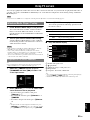
Playback.................................................................24
Basic procedure........................................................ 24
Using the SCENE function ...................................... 24
Selecting a source on the GUI screen ...................... 25
Muting audio output................................................. 25
Adjusting high/low frequency sounds
(tone control) ....................................................... 25
Enjoying pure hi-fi sound ........................................ 25
Using your headphones............................................ 26
Changing information on the front panel display .... 26
Enjoying the sound field programs ..................... 27
Selecting sound field programs................................ 27
Enjoying unprocessed input sources
(Straight decode mode)........................................ 30
Enjoying sound field programs without surround
speakers (Virtual CINEMA DSP) ....................... 30
Enjoy sound field programs with headphones
(SILENT CINEMA™) ........................................ 30
Using CINEMA DSP 3D mode ............................... 30
FM/AM tuning ...................................................... 31
Tuning into the desired FM/AM station
(Frequency tuning) .............................................. 31
Registering FM/AM stations and tuning in
(Preset tuning)...................................................... 31
Radio Data System tuning....................................33
Displaying the Radio Data System information ...... 33
Selecting the Radio Data System program type
(PTY Seek) .......................................................... 33
Using the enhanced other networks (EON) data
service.................................................................. 34
Using iPod™ ..........................................................35
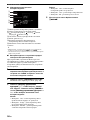
Controlling iPod™................................................... 35
Using Bluetooth™ components ........................... 37
Pairing the Bluetooth™ wireless audio receiver
and your Bluetooth™ component........................ 37
Playback of the Bluetooth™ component ................. 37
Using USB storage devices................................... 38
Playback of the USB storage device........................ 38
Using PC servers................................................... 39
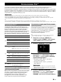
Windows Media Player 11 setup ............................. 39
Playback of PC music contents................................ 39
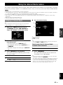
Using the Internet Radio feature......................... 41
Listening to Internet Radio ...................................... 41
Other functions ..................................................... 42
Selecting the HDMI OUT jack ................................ 42
Using the HDMI™ control function........................ 42
Using the sleep timer ............................................... 42
Setting the option menu for each input source
(Option menu)................................................... 43
Option menu items................................................... 43
Selecting a video signal to be output ....................... 45
Operating various settings for this unit
(Setup menu) ..................................................... 46
Basic operation of the Setup menu .......................... 48
Using multi-zone configuration ........................... 58
Connecting Zone2/3................................................. 58
Controlling Zone2/3................................................. 60
Controlling other components with the remote
control................................................................ 61
Setting remote control codes.................................... 61
Resetting all remote control codes........................... 61
Programming from other remote controls ............... 62
Advanced setup..................................................... 63
Troubleshooting .................................................... 65
Glossary ................................................................. 76
Sound field program information ....................... 79
Information on HDMI™...................................... 80
Specifications......................................................... 81
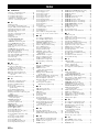
Index ...................................................................... 82
(at the end of this manual)
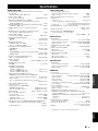
Contents
INTRODUCTION
PREPARATION
BASIC OPERATION
ADVANCED OPERATION
APPENDIX
Information about software...................................i
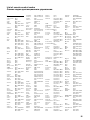
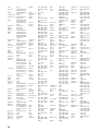
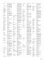
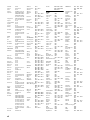
List of remote control codes.................................iii

2 En
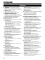
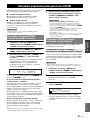
INTRODUCTION
■ Built-in 7-channel power amplifier
• Minimum RMS Output Power (20 Hz to 20 kHz, 0.08%
THD, 8 Ω)
• FRONT L/R: 130 W + 130 W
• CENTER: 130 W
• SURROUND L/R: 130 W + 130 W
• SURROUND BACK L/R: 130 W + 130 W
■ Speaker/Preout outputs
• Speaker terminals (7-channel), extra speaker terminals
(2-channel for presence or Zone2, 2-channel for
Zone3), preout jacks (7.1-channel)
■ Input/Output terminals
Input terminals
• HDMI input x 5 (rear x 4, front V-AUX x 1)
• Audio/Video input
[Audio] Digital input (coaxial) x 2, digital input
(optical) x 2, analog input x 3 (rear x 2, front V-AUX
x 1)
[Video] Component video x 2, S-video x 1, Video x 5
(rear x 4, front V-AUX x 1)
• Audio input (analog) x 2
• Phono input (analog) x 1
• Multi-channel audio input (7.1-channel)
• DOCK terminal to connect a Yamaha iPod universal
dock (such as YDS-11, sold separately) or Bluetooth
wireless audio receiver (such as YBA-10, sold
separately)
• USB port to connect a USB storage device
• NETWORK port to connect a PC or access the Internet
Radio via LAN
Output terminals
• Monitor output
[Audio/Video] HDMI x 2
[Video] Component video x 1, Video x 1
• Audio/Video output
[Audio] Analog x 1
[Video] Video x 1
• Audio output
Digital (optical) x 1, Analog x 1
• Zone2/3 output
Analog x 2
Other terminals
Remote input x 1, Remote output x 1
Trigger output x 2
■ Proprietary Yamaha technology for the
creation of sound fields
• CINEMA DSP 3D
• Compressed Music Enhancer mode
• Virtual CINEMA DSP
• SILENT CINEMA
■ Digital audio decoders
• Dolby TrueHD, Dolby Digital Plus decoder
• DTS-HD Master Audio, DTS-HD High Resolution
Audio, DTS Express
• Dolby Digital/Dolby Digital EX decoder
• DTS, DTS 96/24 decoder, DTS-ES Matrix 6.1, DTS-ES
Discrete 6.1
• Dolby Pro Logic/Dolby Pro Logic II/Dolby Pro Logic
IIx decoder
• DSD decoder
• DTS NEO:6 decoder
■ Sophisticated FM/AM tuner
• 40-station random and direct preset tuning
• Automatic preset tuning
• Radio Data System tuning
■
HDMI™ (High-Definition Multimedia Interface)
• HDMI interface for standard, enhanced or high-
definition video as well as multi-channel digital audio.
– Automatic audio and video synchronization (lip sync)
information capability
– Deep Color video signal (30/36 bit) transmission
– “x.v.Color” video signal transmission capability
– High refresh rate and high resolution video signals
– High definition digital audio format signals capability
• Analog to analog and HDMI digital video up-
conversion (video ↔ component video → HDMI)
capability for monitor out
•
Analog video input up-scaling for HDMI digital video
output 480i(576i) or 480p(576p)
→
720p, 1080i or 1080p
• HDMI control function supported
• Dual HDMI output (possible to select individual or
simultaneous output)
■ Automatic speaker setup features
• “YPAO” (Yamaha Parametric room Acoustic
Optimizer) for automatically optimizing speaker
outputs suitable for listening environments.
■ Other features
• 192-kHz/24-bit D/A converter
• GUI (graphic user interface) menus to optimize this unit
to suit individual audiovisual system
• iPod, USB and PC file browsing
• Album art display capability
• Pure Direct mode for pure hi-fi sound for all sources
• Adaptive dynamic range controlling capability
• SCENE function for changing input sources and sound
field programs with one key
• Bi-amplification connection capability
• Multi-zone function (Zone2/3)
• DHCP automatic or manual network configuration
Features

3 En
English
INTRODUCTION
ADDITIONAL
INFORMATION APPENDIX
PREPARATION
BASIC
OPERATION
ADVANCED
OPERATION
Manufactured under license from Dolby Laboratories.
Dolby, Pro Logic and the double-D symbol are trademarks of Dolby
Laboratories.
Manufactured under license under U.S. Patent No’s:
5,451,942;5,956,674;5,974,380;5,978,762;6,226,616;6,487,535 &
other U.S. and worldwide patents issued & pending. DTS is a
registered trademark and the DTS logos, Symbol, DTS-HD and DTS-
HD Master Audio are trademark of DTS, Inc. © 1996-2007 DTS, Inc.
All Rights Reserved.
iPod™
“iPod” is a trademark of Apple Inc., registered in the U.S. and other
countries.
MPEG Layer-3 audio coding technology licensed from
Fraunhofer IIS and Thomson.
This receiver supports network connections.
Bluetooth
™
Bluetooth is a registered trademark of Bluetooth SIG and is used by
Yamaha in accordance with a license agreement.
“HDMI”, the “HDMI” logo and “High-Definition Multimedia
Interface” are trademarks, or registered trademarks of HDMI
Licensing LLC.
x.v.Color
“x.v.Color” is a trademark of Sony Corporation.
“SILENT CINEMA” is a trademark of Yamaha Corporation.
Windows XP, Windows Vista, Windows Media Audio, Windows
Media Connect and Windows Media Player are either registered
trademarks or trademarks of Microsoft corporation in the United
States and/or other countries.
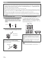
Check that you received all of the following parts.
• Remote control (page 6)
• Simplified remote control (page 8)
• Batteries (2) (AAA, R03, UM-4) (page 6)
• Power cable (page 20)
• Controls diagram
• Optimizer microphone (page 21)
• AM loop antenna (page 20)
• Indoor FM antenna (page 20)
• VIDEO AUX input cover (page 19)
About this manual
• Some operations can be performed by using either the keys on the front panel or the ones on the remote control. In case the key names differ between
the front panel and the remote control, the key name on the remote control is given in parentheses.
• This manual is printed prior to production. Design and specifications are subject to change in part as a result of improvements, etc. In case of
differences between the manual and product, the product has priority.
• For better viewing, we increase the size of characters used in example screen images in this manual. Therefore the size ratio of characters to other
objects (such as icons) may be different from that of the actual display image.
• “LMAIN ZONE ON/OFF” or “dHDMI 1” (example) indicates the name of the parts on the front panel or the remote control. Refer to the
attached sheet or “Part names and functions” (page 4) for the information about each position of the parts.
• ☞ indicates the page describing the related information.
• y indicates a tip for your operation.
Supplied accessories

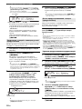
4 En
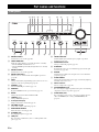
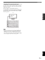
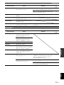
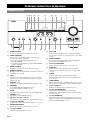
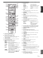
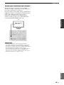
A ZONE2 ON/OFF
Switches Zone2 on and off (page 60).
B HDMI THROUGH
Lights up in the following cases while this unit is on standby.
• when the HDMI control function is on
• when the HDMI signal standby-through function is currently
working
C ZONE3 ON/OFF
Switches Zone3 on and off (page 60).
D ZONE CONTROLS
Selects a zone to control with the main amplifier operations
(page 60).
E INFO
Changes information (input, DSP program, audio decoder, etc)
displayed on the front panel display (page 26).
F PRESET l / h
Selects an FM/AM preset station (page 32).
G MEMORY
Registers FM/AM stations as preset stations (page 32).
H BAND
Change the tuner bands between FM and AM.
I TUNING l / h
Changes FM/AM frequencies.
J Front panel display
Displays information on this unit (page 6).
K VOLUME control
Controls the volume of this unit (page 24).
L MAIN ZONE ON/OFF
Turns this unit on and off (page 20).
M PHONES jack
For plugging headphones (page 26).
N USB port
For connecting a USB memory device or USB portable audio
player (page 19)
O TONE CONTROL
Adjusts high-frequency/low-frequency output of speakers/
headphones (page 25).
P PROGRAM selector
Changes sound field programs (page 27).
Q STRAIGHT
Toggles between the selected sound field program and straight
decode mode (page 30).
R SCENE
Switches between linked sets of input sources and sound field
programs (page 24).
S PURE DIRECT
Changes mode to Pure Direct mode (page 25). This key lights up
when Pure Direct mode is on.
T INPUT selector
Selects an input source (page 24).
U OPTIMIZER MIC jack
For connecting the supplied optimizer microphone and adjusting
output characteristics of speakers (page 21).
V VIDEO AUX jacks
For connecting a game console, camcorder or digital camera to
either the HDMI IN jack or analog AUDIO/VIDEO jacks
(page 19).
Part names and functions
Front panel
ON/OFF
PHONES
MAIN ZONE
SILENT CINEMA
TONE CONTROL
PROGRAM
STRAIGHT PURE DIRECT
INPUT
OPTIMIZER MIC
VIDEO
HDMI IN
AUDIO
THROUGH
VIDEO
AUX
VOLUME
HDMI
EFFECT
BD/DVD
TV
CD
RADIO
SCENE
INFO
PRESET
l
h
l
h
MEMORY
ZONE2
ON/OFF
ZONE
CONTROLS
ZONE3
ON/OFF
BAND
TUNING
USB
LPSOQ T
ABC D E G HFIJK
UMN R V

5 En
Part names and functions
English
INTRODUCTION
ADDITIONAL
INFORMATION APPENDIX
PREPARATION
BASIC
OPERATION
ADVANCED
OPERATION
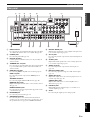
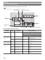
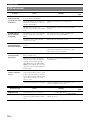
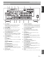
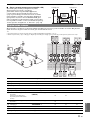
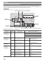
a DOCK terminal
For connecting an optional Yamaha iPod universal dock (YDS-
11) or Bluetooth wireless audio receiver (YBA-10) (page 18).
b PHONO jacks
For connecting a turntable (page 16).
c RS-232C terminal
Control expansion terminal for factory use only. Consult your
dealer for details.
d TRIGGER OUT 1/2 jacks
For connecting an external terminal with a trigger input terminal
to operate it linked with operation of this unit. Consult your
dealer for details.
e HDMI OUT 1/2 jacks
For connecting HDMI-compatible video monitors (page 14).
HDMI 1-4 jacks
For connecting external components for HDMI inputs 1-4
(page 16).
ANTENNA terminals
For connecting supplied FM and AM antennas (page 20).
MONITOR OUT jacks
Output visual signals from this unit to a video monitor, such as a
TV (page 14).
REMOTE IN/OUT jacks
For connecting an external component that supports the remote
control function (page 18).
f NETWORK port
For connecting to the network (page 19).
g SPEAKERS terminals
For connecting front, center, surround and surround back
speakers (page 11). Connect the presence speakers (page 11) or
the speakers for Zone2/3 (page 59) to EXTRA SP terminals.
h DIGITAL AUDIO jack
Outputs audio signals from a selected digital audio input source
to an external component (page 16).
i AV 1-6 jacks
For connecting external components for audio/visual inputs 1-6
(page 16).
j AV OUT jacks
Output audio/visual signals from a selected analog input source
to an external component (page 16).
k AUDIO 1/2 jacks
For connecting external components for audio inputs 1-2
(page 16).
l MULTI CH INPUT jacks
For connecting a player that supports a multi-channel output
(page 18).
m AUDIO OUT jacks
Output audio signals from a selected analog input source to an
external component (page 16).
ZONE2/3 OUT jacks
Output sound of this unit to an external amplifier set in a
different zone (page 58).
n PRE OUT jacks
Output multi-channel signals from up to 7.1 channels to an
external amplifier (page 18).
o AC IN
For connecting the supplied power cable (page 20).
Rear panel
DOCK
RS
-
232C
TRIGGER OUT
NETWORK
COMPONENT
VIDEO
P
R
P
B
12
Y
OPTICAL
OPTICAL
OUT
(
TV
)
A
V
1
AV 2
COAXIAL
AV 3
(
CD
)
COAXIAL
OPTICAL
AV 4
AV 5
AV 6
AV
OUT
AUDIO1
AUDIO2
FRONT
SURROUND
SUR.BACK
SUBWOOFER
MULTI CH INPUT
AUDI O
OUT
ZONE3
OUT
ZONE2
OUT
FRONT
SURROUND
SUR. BACK SUBWOOFER
PRE OUT
CENTER
SINGLE
VIDEO
HDMI OUT 2HDMI OUT 1
ANTENNA
PHONO
UNBAL.
FM
GND
S VIDEO
AM
HDMI 1
(
BD/DVD
)
(
HDMI CONTROL
)
HDMI 2
HDMI 3
HDMI 4
VIDEO
IN
OUT
MONITOR OUT
SPEAKERS
12V
0.1A MAX.
FRONT
CENTER
SINGLE
SURROUND
SURROUND BACK/
BI-AMP
ZONE2/PRESENCEZONE3
12
CENTER
P
R
P
B
Y
REMOTE
COMPONENT
VIDEO
DIGITAL
AUDIO
EXTRA SP
SP2 SP1
GND
AC IN
cab
ijhklmno
dfeg

6 En
Part names and functions
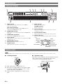
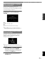
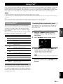
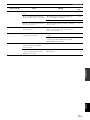
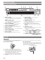
a HDMI indicator
Lights up during normal communication when HDMI is
selected as an input source.
OUT 1/OUT 2 indicators
The respective indicator lights up when HDMI signals are
output from the HDMI OUT 1/2 jacks.
b CINEMA DSP indicator
Lights up when a sound field program that uses CINEMA DSP
is selected.
c CINEMA DSP 3D indicator
Lights up when CINEMA DSP 3D is activated.
d Tuner indicator
Lights up during receiving radio broadcast signals from an FM/
AM station (page 31).
e ZONE2/ZONE3 indicator
Lights up when Zone2 or Zone3 is turned on.
f SLEEP indicator
Lights up when the sleep timer is activated (page 42).
g MUTE indicator
Flashes when audio is muted.
VOLUME indicator
Displays volume levels.
h Cursor indicators
Light up if corresponding cursors on the remote control are
available for operations.
i Multi information display
Displays menu items and settings for the current operation.
j Speaker indicators
Indicate speaker terminals from which signals are currently
output.
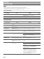
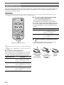
Note
• Before installing batteries or using the remote control, make sure that you read “Notes on remote controls and batteries” in the “Caution” section.
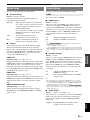
■ Installing batteries
a Take off the battery compartment cover.
b Insert the two supplied batteries (AAA, R03, UM-4)
according to the polarity markings (+ and -) on the
inside of the battery compartment.
c Snap the battery compartment cover back into the
place.
■ Operation range
The remote control transmits a directional infrared ray. Be
sure to aim the remote control directly at the remote
control sensor on this unit during operation.
Front panel display
STEREO
SLEEP
VOL.
TUNED
PL PR
SW
C
LR
SL SR
SBL SB SBR
MUTE
3
ZONE
2
ZONE
3
OUT 1 OUT 2
acbfedg
hi jh
SW
C
LR
SL SR
SBL SB SBR
PL PR
Subwoofer
Front L
Surround L
Surround back L
Center
Front R
Surround R
Surround back R
Surround back
Presence L Presence R
Remote control
a
c
b
30 30
Remote control sensor window
within 6 m (20 ft)

7 En
Part names and functions
English
INTRODUCTION
ADDITIONAL
INFORMATION APPENDIX
PREPARATION
BASIC
OPERATION
ADVANCED
OPERATION
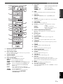
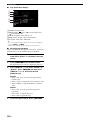
a Remote control signal transmitter
Transmits infrared signals.
b Zone selection switch
Switches amplifiers (main, Zone2 or Zone3) to be operated by
the remote control (page 60).
c SOURCE POWER
Switches an external component on and off.
d Input selection keys
e Tuner keys
f INFO
Changes the information shown on the front panel display
(page 26).
g HDMI OUT
Switches the HDMI OUT jacks to output HDMI signals
(page 42).
h SCENE
Switches between linked sets of input sources and sound field
programs (page 24).
i ON SCREEN
Displays the GUI screen (page 25).
k External component operation keys
Operate recording, playback etc. of external components
(page 61).
l Numeric keys
Enter numbers.
m TV control keys
Enables operations of a TV or a projector (page 61).
n TRANSMIT
Lights up when a signal is output from the remote control.
o CODE SET
Sets remote control codes for external component operations
(page 61).
p POWER
Switches this unit on and standby (page 20).
q SLEEP
Switches the sleep timer operations (page 42).
r Sound selection keys
Selects sound field programs (page 27).
s OPTION
Displays the Option menu (page 43).
t VOLUME +/–
Adjust the volume of this unit (page 24).
u DISPLAY
Displays the play information on the video monitor.
When an iPod is connected: Changes the operation mode of the
iPod connected to the Yamaha iPod universal dock (page 35).
v MUTE
Turns the mute function on and off (page 25).
w Sub-input selection keys
Selects USB, NET RADIO or PC when “USB/NET” is selected
as the input source.
HDMI 1-4
Selects HDMI inputs 1 through 4.
AV 1-6
Selects AV inputs 1 through 6.
AUDIO 1/2
Selects AUDIO inputs 1 and 2.
V-AUX
Selects a signal input from the VIDEO AUX jacks.
PHONO
Selects a signal input from the PHONO jacks.
MULTI
Selects a signal input from the MULTI CH
INPUT jacks.
DOCK
Selects a Yamaha iPod universal dock/Bluetooth
wireless audio receiver connected to the DOCK terminal.
TUNER
Selects the FM/AM tuner.
USB/NET
Selects a USB device or a signal input via
network (selected by wSub-input
selection keys).
BD
DVD
TV
CD
RADIO
SLEEP
FM AM
INFO
MEMORY
1 2 3
4
1 2 3
4
5 6 1
2
PHONO
MULTI
DOCK
TUNER
V-AU X
HDMI
MUSIC
STEREO
ENHANCER SUR. DECODE
MOVIE
MUTE
STRAIGHT
HDMI OUT
PURE DIRECT
USB/NET
PRESET TUNING
ON SCREEN OPTION
SOURCE
POWER
7 85 6
9 0
1 2 3 4
USB NET RADIO PC
TOP
MENU
SCENE
RETURN
REC
ENT
POWER
TV
INPUT
MUTE
ENTER
VOLUME
DISPLAY
MENU
HDMI
AUDIO
TRANSMIT
CODE SET
10
TV VOL TV CH
MAIN
ZONE 2
ZONE 3
AV
POWER
p
q
s
r
t
u
v
w
o
n
a
c
d
e
g
h
i
k
l
m
b
j
f
FM/AM
Switches a band between FM and AM.
MEMORY
Presets radio stations.
PRESET k / n
Selects a preset station.
TUNING k / n
Changes FM/AM frequencies.
j Cursors k / n / l / h
Select menu items or change
settings.
ENTER
Confirms a selected item.
RETURN
Returns to the previous screen or
ends the menu display.

8 En
Part names and functions
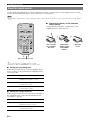
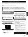
Use the supplied simplified remote control to make basic controls of this unit. Keys on the simplified remote control
function as well as the identical keys on the main remote control (page 6).
Note
• Before using the simplified remote control or replacing the battery, make sure that you read “Notes on remote controls and batteries” in the “Caution”
section.
y
• To select an input source, press INPUT l / h repeatedly.
• The printings “TAG” and “PRG SELECT” are for U.S.A. model.
■ Setting the controlling zone
Follow the procedure below to select an amplifier (main,
Zone2 or Zone3) to be operated by the simplified remote
control (page 60).
■ Setting the remote control ID
Follow the procedure below to set the remote control ID of
the simplified remote control. For details about remote
control ID, see page 64.
■ Replacing the battery of the simplified
remote control
Change the battery when the operation range of the
simplified remote control decreases.
Simplified remote control
Zone to select Procedure
Main Press and hold h (right of ENTER) and
BD/DVD for more than 3 seconds.
Zone2 Press and hold h (right of ENTER) and TV
for more than 3 seconds.
Zone3 Press and hold h (right of ENTER) and CD
for more than 3 seconds.
Zone to select Procedure
ID1 Press and hold l (left of ENTER) and BD/
DVD for more than 3 seconds.
ID2 Press and hold l (left of ENTER) and TV
for more than 3 seconds.
MUTE
VOLUME
INPUT
SLEEP
SCENE
BD
DVD
TV CD
RADIO
POWER
ON SCREEN
OPTION
TAG
PRESET
PRG SELECT
ENTER
DISPLAYRETURN
Remove the insulation sheet
Use a straight
pin to remove
the cover.
Replace the
battery with a
new CR2025
battery.
Close the
cover.

9 En
English
INTRODUCTION
ADDITIONAL
INFORMATION APPENDIX
PREPARATION
BASIC
OPERATION
ADVANCED
OPERATION
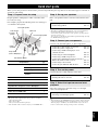
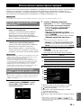
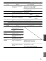
When you use this product for the first time, perform setup following the steps below. See the related pages for details on
operations and settings.
Prepare speakers, DVD player, cables, and other items
necessary for setup.
For example, prepare the following items for setting up a
7.1-channel sound system.
y
• The priority of the requirement of other speakers is as follows:
1 Two surround speakers
2 One center speaker
3 One (or two) surround back speaker(s)
• Video and audio cables are unnecessary if you use HDMI cables.
Place your speakers in the room and connect them to this
unit.
y
• This unit has a YPAO (Yamaha Parametric room Acoustic Optimizer)
that automatically optimizes this unit based on room acoustic
characteristics (audio characteristics of the speakers, speaker positions,
and room acoustics, etc.).
You can enjoy good balanced sound without special knowledge by using
the YPAO technology (page 21).
Connect your TV, DVD player, or other components.
Connect the power cable and turn on this unit.
Select the component connected in step 3 as an input
source and start playback.
y
• This unit supports the SCENE function (page 24) that changes the input
source and sound field program at one time. Four scenes are preset for
different purposes for Blu-ray disc, DVD and CD, and you can select
from a scene from those just by pressing a remote control key.
Quick start guide
Step 1: Prepare items for setup
Requirements qty.
Speakers Front speaker 2
Center speaker 1
Surround speaker 2
Surround back
speaker
2
Active subwoofer 1
Speaker cable 7
Subwoofer cable 1
Reproduction component such as DVD player 1
Video monitor such as TV 1
Video cable or HDMI cable 2
Audio cable 2
Front right speaker
Subwoofer
Surround left speaker
Surround right speaker
Front left
speaker
Video monitor
Center
speaker
Components
(such as DVD player)
Surround Back
right speaker
Surround Back
left speaker
Step 2: Set up your speakers
• Placing speakers ☞P. 1 0
• Connecting speakers ☞P. 1 1
Step 3: Connect your components
• Connecting a TV monitor or projector ☞P. 14
• Connecting other components ☞P. 1 6
• Connecting a multi-format player or an
external decoder ☞P. 1 8
• Connecting an external amplifier ☞P. 1 8
• Connecting a USB storage device ☞P. 1 9
• Connecting a Yamaha iPod universal dock or
Bluetooth wireless audio receiver ☞P. 1 8
• Connecting to the network ☞P. 1 9
• Connecting the FM and AM antennas ☞P. 2 0
Step 4: Turn on the power
• Connecting the power cable ☞P. 2 0
• Turning this unit on and off ☞P. 2 0
Step 5: Select the input source and start
playback
• Basic procedure ☞P. 2 4
• Selecting sound field programs ☞P. 2 7

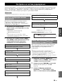
10 En
PREPARATION
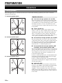
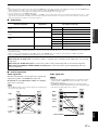
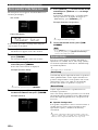
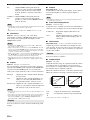
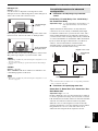
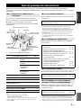
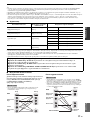
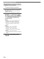
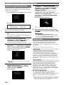
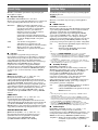
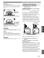
This unit supports up to 7.1-channel surround. We recommend the following speaker layout in order to obtain the
optimum surround effect.
7.1-channel speaker layout
6.1-channel speaker layout
5.1-channel speaker layout
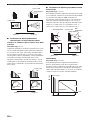
■ Front left and right speakers (FL and FR)
The front speakers are used for the front channel sounds
(stereo sound) and effect sounds. Place these speakers at
an equal distance from the ideal listening position. Adjust
the height of the TV or screen so that about 1/4 of the
screen from the bottom is aligned with the tweeters of the
front speakers.
■ Center speaker (C)
The center speaker is for the center channel sounds
(dialog, vocals, etc.). Place it halfway between the left and
right speakers. When using a TV, place the speaker just
above or just under the center of the TV with the front
surfaces of the TV and the speaker aligned. When using a
screen, place it just under the center of the screen.
■ Surround left and right speakers (SL and SR)
The surround speakers are used for effect and surround
sounds. Place them at the rear left and rear right facing the
listening position. To obtain a natural sound flow in the
5.1-channel speaker layout, place them slightly further
back than in the 7.1-channel speaker layout.
■ Surround back left and right speakers (SBL
and SBR) / Surround back speaker (SB)
The surround back left and right speakers are used for rear
effect sounds. Place them at the rear of the room facing the
listening position at least 30 cm (1 ft) away from each
other, ideally at the same distance as that between the
front left and right speakers.
In the 6.1-channel speaker layout, surround back left and
right channel sound signals are mixed down and output
from the single surround back speaker.
In the 5.1-channel speaker layout, surround back left and
right channel sound signals are output from the surround
left and right speakers.
■ Subwoofer (SW)
The subwoofer speaker is used for bass sounds and low-
frequency effect (LFE) sounds included in Dolby Digital
and DTS signals. Use a subwoofer with a built-in
amplifier, such as the Yamaha Active Servo Processing
Subwoofer System. Place it exterior to the front left and
right speakers facing slightly inward to reduce reflections
from a wall.
Connections
Placing speakers
60˚
30˚
SBR
SBL
FL
FR
C
SL
SR
SR
80˚
SL
SW
SW
30 cm (12 in) or more
60˚
30˚
SB
FL
FR
C
SL
SR
SR
80˚
SL
SW
SW
60˚
30˚
FL
FR
C
SL
SR
SR
80˚
SL
SW
SW
Speaker channels

11 En
Connections
English
INTRODUCTION
ADDITIONAL
INFORMATION APPENDIX
PREPARATION
BASIC
OPERATION
ADVANCED
OPERATION
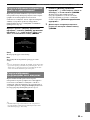
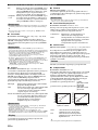
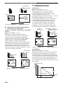
■ Presence left and right speakers (PL and PR)
The presence speakers supplement the sound from the
front speakers with extra ambient effects produced by the
sound field programs (page 27). We recommend that you
use the presence speakers especially for the CINEMA
DSP sound field programs. To use the presence speakers,
connect the speakers to SP1 terminals and then set “Extra
Speaker Assignment” to “Presence” (page 49).
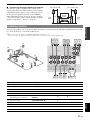
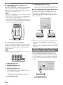
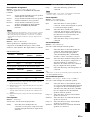
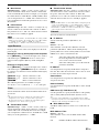
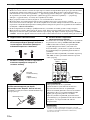
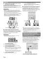
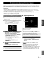
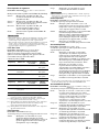
Connect your speakers to the respective terminals according to your speaker layout. The following illustration shows how
to connect speakers for 7.1-channel speaker layout.
y
• You can connect Zone2/3 speakers to the EXTRA SP (SP1/SP2) terminals (page 59).
• You can connect up to two subwoofers. When two subwoofers are connected, the same sound is output from them.
FR
PRPL
C
FL
0.5 to 1 m (1 to 3 ft)0.5 to 1 m (1 to 3 ft)
1.8 m
(6 ft)
1.8 m
(6 ft)
1/4 from
bottom
Connecting speakers
a
b
c
d
e
f
g
h
i
j
k
SUBWOOFER
SPEAKERS
FRONT
CENTER
SINGLE
CLASS 2 WIRING
CABLAGE
CLASSE 2
SURROUND
SURROUND BACK/
BI-AMP
ZONE2/PRESENCE
12
SP1
NETW
O
R
K
SU
R.
B
AC
K
SU
B
W
OO
FE
R
H
INPUT
AU
DI
O
OU
T
Z
O
NE3
OUT
Z
O
NE2
OUT
FR
O
N
T
S
URR
O
UN
D
S
UR
.
BA
C
K
PRE O
U
T
C
ENTER
S
INGL
E
3
HDMI
4
C
ENTER
E
c
g f
h i
e d
b a
k j
Speakers Jacks on this unit 7.1-channel 6.1-channel 5.1-channel
a Front left FRONT (L) ✔✔✔
b Front right FRONT (R) ✔✔✔
c Center CENTER ✔✔✔
d Surround left SURROUND (L) ✔✔✔
e Surround right SURROUND (R) ✔✔✔
f Surround back left
(Surround back for 6.1-channel)
SURROUND BACK (L)
(SINGLE)
✔✔
g Surround back right SURROUND BACK (R) ✔
h Subwoofer 1 SUBWOOFER 1 ✔✔✔
i Subwoofer 2 SUBWOOFER 2 Option Option Option
j Presence left SP1 (L) Option Option Option
k Presence right SP1 (R) Option Option Option

12 En
Connections
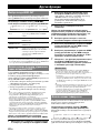
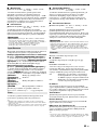
■ Connecting speaker cables
1 Remove approximately 10 mm (0.4 in) of
insulation from the end of each speaker
cable and then twist bare wires of the cable
together so that they will not cause a short
circuits.
2 Loosen the knob, insert the twisted bare
wires into the hole and then tighten the knob.
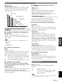
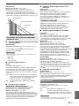
■ Using bi-amplification connections
If you do not connect surround back speakers, you can use
the SURROUND BACK/BI-AMP jacks to make bi-
amplification connections to one speaker system which
supports bi-amplification connection as shown below.
To activate the connections, set “BI-AMP” to “ON” in the
advanced setup menu (page 63).
Note
• You cannot use surround back speakers or extra speakers (presence and
Zone2 speakers) when bi-amplification connections are made.
Caution
• A speaker cable is a pair of insulated cables running side by side in general. One of the cables is colored differently
or striped to indicate a polarity. Connect one end of the colored/striped cable to the “+” (red) terminal of this unit
and the other end to that of your speaker, and connect one end of the other cable to the “–” (black) terminal of this
unit and the other end to that of your speaker.
• Before connecting the speakers, be sure to disconnect the power cable.
• Do not let the bare speaker wires touch each other or any metal part of this unit. This could damage this unit and/or
speakers. If the circuit shorts out, “CHECK SP WIRES!” appears on the front panel display when this unit is turned
on.
• If images on the monitor (CRT) are distorted, place the speakers away from the video monitor.
• Use speakers with an impedance of 6-ohm or larger. Set speaker impedance in the advanced setup menu before
connecting the speakers (page 63). You can also use 4-ohm speakers as the front speakers when you set “SP IMP.” to
“6ΩMIN”.
Connecting the banana plug (Except Korea,
U.K., Europe, Russia and Asia models)
Tighten the knob and then insert the banana plug into
the end of the terminal.
10 mm (0.4 in)
1
2
3
Red: positive (+)
Black: negative (–)
Banana plug
Caution
Before making bi-amplification connections, remove
any brackets or cables that connect a woofer with a
tweeter. Refer to the instruction manuals of speakers for
details.
When not making bi-amplification connections, make
sure that the brackets or cables are connected before
connecting the speaker cables.
SURROUND BACK/
BI-AMP
FRONT
Front speakers
Right Left
This unit

13 En
Connections
English
INTRODUCTION
ADDITIONAL
INFORMATION APPENDIX
PREPARATION
BASIC
OPERATION
ADVANCED
OPERATION
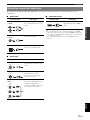
This unit has the following input and output jacks. Use jacks and cables appropriate for components that you are
connecting.
■ Audio jacks
■ Video jacks
■ Video/audio jacks
y
• We recommend that you use a commercially available 19-pin HDMI
cable no longer than 5 meters (16 feet) with the HDMI logo printed on it.
• Use a conversion cable (HDMI jack ↔ DVI-D jack) to connect this unit
to other DVI components.
• You can check the potential problem about the HDMI connection
(page 44).
Information on jacks and cable plugs
Jack and cables Description
Analog audio jacks To transmit conventional analog
stereo audio signals. Use stereo pin
cables.
COAXIAL jacks To transmit coaxial digital audio
signals. Use pin cables.
OPTICAL jacks To transmit optical digital audio
signals. Use optical fiber cables.
Jack and cables Description
VIDEO jacks To transmit conventional
composite video signals. Use pin
cables.
S VIDEO jack To transmit S-video signals that
include luminance (Y) and
Cameroonians (C) components.
Use an S-video cable.
COMPONENT VIDEO
jacks
To transmit component video
signals that include luminance (Y),
chrominance blue (PB) and
chrominance red (PR) components.
Use component video cables.
L
R
(white)
(red)
COAXIAL
C
(orange)
OPTICAL
O
VIDEO
V
(yellow)
S VIDEO
S
PR
PB
Y
COMPONENT
VIDEO
P
B
Y
P
R
(red)
(blue)
(green)
Jack and cables Description
HDMI jacks To transmit digital video and
digital audio signals. Use HDMI
cables.
HDMI
HDMI

14 En
Connections
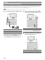
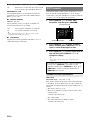
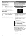
According to the types of video input jacks available on your video monitor (such as a TV or projector), choose one of
the connection methods as shown below. When you connect video players such as a DVD player to this unit with an
HDMI connection, connect your video monitor to this unit with an HDMI connection.
Note
• Make sure that this unit and other components are unplugged from the AC wall outlets.
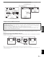
■ If your video monitor has an HDMI input jack
y
• This unit is equipped with two HDMI OUT jacks. You can select the
active HDMI OUT jack(s) by pressing gHDMI OUT (page 42).
• This unit supports the HDMI control function (page 42). If your TV
supports the HDMI control function, connect the TV to the HDMI OUT
1 jack to control this unit with the remote control of your TV.
■ If your video monitor does not have HDMI
input jacks but component video input jacks
■ If your video monitor has neither HDMI nor
component video input jacks
Connecting a TV monitor or projector
Jacks on components Jacks on this unit
a HDMI input HDMI OUT 1
b HDMI input HDMI OUT 2
HDMI OUT 2HDMI OUT 1
(
HDMI CONTROL
)
TRI
GG
ER
OU
T
12
H
DMI
1
(
BD
/
DV
D
)
HDMI
2
HDMI
3
VIDEO
IN
O
U
T
MONI
T
O
R OU
T
12
V
0
.1A MAX.
P
REM
OT
E
CO
MP
O
NENT
G
ND
a
HDMI
HDMI
b
TV
Projector
Jacks on components Jacks on this unit
c Component video output MONITOR OUT
(COMPONENT VIDEO)
Jacks on components Jacks on this unit
d Video input (composite) MONITOR OUT (VIDEO)
M
O
NI
T
O
R
OUT
P
R
P
B
Y
COMPONENT
VIDEO
TRI
GG
ER
OU
T
12
2
H
DMI
O
UT
HDMI
1
(
BD
/
DV
D
)
H
DMI
2
H
DMI
3
VIDE
O
IN
OUT
12V
0.1
A
MAX
.
REM
OT
E
c
P
B
YP
R
TV
VIDEO
MO
NIT
OR OUT
T
RI
GG
ER
OU
T
12
VIDE
O
2
H
DMI
OU
T
HDMI
1
(
B
D
/
DV
D
)
HDMI
2
HDMI
3
IN
O
UT
O
O
12V
0
.1A MAX
.
REM
O
T
E
CO
MP
O
NEN
T
V
d
TV

15 En
Connections
English
INTRODUCTION
ADDITIONAL
INFORMATION APPENDIX
PREPARATION
BASIC
OPERATION
ADVANCED
OPERATION
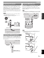
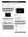
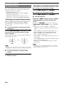
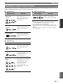
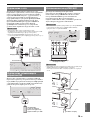
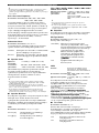
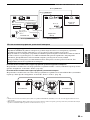
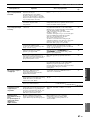
To output sound of a TV from this unit, make connection
between one of the AV 1-6 jacks of this unit and an audio
output jack of the TV.
If the TV supports an optical digital output, we
recommend that you use the AV 1 jack. Connecting to the
AV 1 jack allows you to switch an input source to the AV 1
jack with a just a single key operation using the SCENE
function (page 24).
Note
• If the video monitor connected to this unit supports the HDMI control
function, we recommend that you connect its audio output jack to the
OPTICAL jack of the AV1 jacks of this unit. By doing so, this unit
automatically turns on and "TV" of SCENE is automatically selected
when you turn on the video monitor. You can obtain the same result even
if you connect the audio output jacks to the AV2-6, AUDIO1-2 or VAUX
jacks by assigning those jacks to TV in advance (page 24).
Outputting TV sounds from this unit
OPTICAL
(
TV
)
A
V
A
1
P
R
P
B
Y
AV
2
CO
AXIAL
AV
3
(
C
D
)
CO
AXIAL
AV
6
AV
O
UT
AU
D
I
O1
AU
D
VIDE
O
P
R
P
B
O
Digital output
(optical)
TV

16 En
Connections
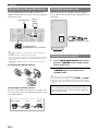
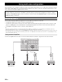
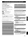
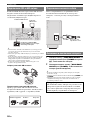
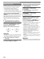
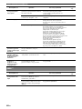
This unit has input and output terminals for respective input and output sources. You can reproduce sound and movies
from input sources selected with the front panel display or remote control.
Note
• Make sure that this unit and other components are unplugged from the AC wall outlets.
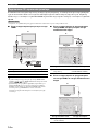
■ Audio and video player / Set-top box
Connecting other components
External
component
Signal
Output jacks on
components
Input jacks on this unit
External component
with HDMI output
Audio/Video HDMI output HDMI 1 (BD/DVD)
HDMI 2
HDMI 3
HDMI 4
External component
with component video
output
Audio Optical digital output AV 1 (TV) OPTICAL
Video Component video output COMPONENT VIDEO
Audio Coaxial digital output AV 2 COAXIAL
Video Component video output COMPONENT VIDEO
External component
with S-video output
Audio Analog audio output AV 5 Analog audio
Video S-video output S VIDEO
External component
with composite video
output
Audio Coaxial digital output AV 3 (CD) COAXIAL
Video Composite output VIDEO
Audio Optical digital output AV 4 OPTICAL
Video Composite output VIDEO
Audio Analog audio output AV 5 Analog audio
Video Composite output VIDEO
Audio Analog audio output AV 6 Analog audio
Video Composite output VIDEO
COMPONENT
VIDEO
P
R
P
B
Y
OPTICAL
OPTICAL
OUT
(
TV
)
A
V
1
AV 2
COAXIAL
AV 3
(
CD
)
COAXIAL
OPTICAL
AV 4
AV 5
AV 6
AV
OUT
AUDIO1
AUDIO2
FRONT
SURROUND
SUR.BACK
SUBWOOFER
MULTI CH INPUT
AUDIO
OUT
VIDEO
PHONO
S VIDEO
HDMI 1
(
BD/DVD
)
HDMI 2
HDMI 3
HDMI 4
CENTER
DIGITAL
AUDIO
GND
D
OC
K
RS
-
232
C
TRI
GG
ER
O
U
T
N
12
Z
O
N
OU
H
DMI
OU
T
2
HDMI
OU
T
1
ANTENNA
UNB
AL
.
FM
G
N
D
AM
(
HDMI
CO
NT
RO
L
)
V
IDE
O
IN
O
UT
MONITOR OU
T
12
V
0.1
A
MAX.
F
R
O
N
T
P
R
P
B
Y
R
EM
O
T
E
CO
MP
O
NEN
T
VIDE
O
Audio / video output (AV OUT)
Audio input (AUDIO 1/2)
HDMI input
(HDMI 1-4)
Audio output
(AUDIO OUT)
Multi channel audio input (MULTI CH INPUT)
Audio output
(DIGITAL AUDIO)
Audio / video input
(AV 1-6)
Audio input (PHONO)

17 En
Connections
English
INTRODUCTION
ADDITIONAL
INFORMATION APPENDIX
PREPARATION
BASIC
OPERATION
ADVANCED
OPERATION
y
• Input jacks in parentheses indicate the jacks to which the SCENE function (page 24) is assigned by the initial factory settings. To use the SCENE function
with the initial factory settings, connect external components that support the SCENE function to these jacks.
• You can change the name of the input source displayed on the front panel display as necessary (page 53).
• See page 58 on how to use the ZONE2/3 OUT jacks.
• You can select the video to be output when “AUDIO1” or “AUDIO2” is selected as the input source or assign another video input jack to “AV3” or “AV4”
(page 45). In case the default combinations of the audio/video input jacks on this unit do not correspond to your external component, change the video
input jack assignments according to your external component.
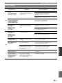
■ Audio player
y
• If your CD player has a coaxial digital output jack, connect it to the AV3 jack of this unit. In this case, you can use the SCENE function (page 24) with the
initial factory settings.
• When connecting a turntable with a low-output MC cartridge to the PHONO jacks, use an in-line boosting transformer or MC-head amplifier.
• Connect your turntable to the GND terminal of this unit to reduce noise in the signal.
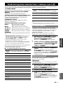
■ Internal signal flow
Video signal flow
This unit automatically converts input video signals and
outputs the signals to the HDMI OUT jacks and
MONITOR OUT (COMPONENT VIDEO and VIDEO)
jacks (video conversion).
Note
• The AV OUT (composite video) jack only outputs video signals input to
the composite video input jacks.
Audio signal flow
Notes
• Audio signals input to the HDMI input jacks are output from either the
speaker terminals or HDMI OUT 1/2 jacks depending on the “Audio
Output” setting (page 51).
• The DIGITAL AUDIO (OPTICAL OUT) jack outputs digital audio
signals only when signals are input to the optical or coaxial optical input
jacks and corresponding input source is selected.
External component
Output jacks on
components
Input jacks on this unit
External component with optical digital
output
Optical digital output AV 1 (TV) OPTICAL
AV 4 OPTICAL
External component with coaxial digital
output
Coaxial digital output AV 2 COAXIAL
AV 3 (CD) COAXIAL
External component with analog audio
output
Analog audio output AV 5 Analog audio
AV 6 Analog audio
AUDIO 1 Analog audio
AUDIO 2 Analog audio
Turntable Analog audio output PHONO Analog audio
About audio/video output jacks
When using the AV OUT jacks: connect these jacks to composite video and analog audio input jacks of an external
component.
When using the AUDIO OUT jacks: connect these jacks to analog audio input jacks of an external component.
When using the DIGITAL AUDIO (OPTICAL OUT) jack: connect this jack to optical digital input jack of an
external component.
HDMI
S VIDEO
VIDEO
P
R
P
B
Y
HDMI OUT
VIDEO
P
R
P
B
Y
HDMI
Component
video
S-video
Input Output
Composite
video
HDMI
OPTICAL
HDMI OUT
OPTICAL
OUT
COAXIAL
HDMI
Optical
digital
Analog
Input Output
MULTI CH INPUT
Speaker
terminals
Coaxial
digital

18 En
Connections
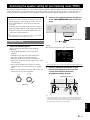
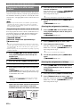
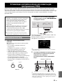
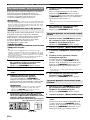
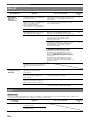
■ Connecting a multi-format player or an
external decoder
This unit is equipped with 8 additional input jacks (Front
L/R, Center, Surround L/R, Surround Back L/R and
Subwoofer) for analog multi-channel input from a multi-
format player, external decoder, etc.
Notes
• When you select “MULTI CH” as the input source, the digital sound field
processor is automatically disabled.
• Since this unit does not redirect signals input at the MULTI CH INPUT
jacks to accommodate for missing speakers, connect at least a 5.1-
channel speaker system when using this feature.
• You can specify a video signal to be output during a multi-channel audio
reproduction (page 45). If your DVD player has analog multi-channel
output jacks, connect them to the MULTI CH INPUT jacks while making
a video connection (component video or composite).
■ Connecting an external amplifier
If you want to use another amplifier, connect an external
amplifier to the PRE OUT jacks. Each PRE OUT jack
outputs the same channel signals as the corresponding
speaker terminals.
Note
• When you make connections to the PRE OUT jacks, do not make any
connections to the speaker terminals.
a FRONT PRE OUT jacks
Front channel output jacks.
b SURROUND PRE OUT jacks
Surround channel output jacks.
c SUR.BACK PRE OUT jacks
Surround back output jacks. When you only connect one
external amplifier for the surround back channel, connect it to
the left SUR.BACK (SINGLE) jack.
y
• To output surround back channel signals at these jacks, set
“Surround Speaker” to any parameter except “None” (page 49).
d CENTER PRE OUT jack
Center channel output jack.
e SUBWOOFER PRE OUT 1/2 jack
Connect a subwoofer with a built-in amplifier. When two
subwoofers are connected, the same sound is output from them.
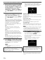
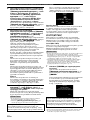
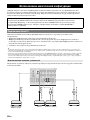
■ Transmitting/receiving remote control signals
When the components have the capability of the
transmission of the remote control signals, connect the
REMOTE IN and REMOTE OUT jacks to the remote
control input and output jack with the monaural analog
mini cable as follows.
y
• If connecting a Yamaha component that supports the SCENE control
signal reception to the REMOTE OUT jack of this unit, you can start
playback on the Yamaha component by using the SCENE function
(page 24).
• If connecting a component other than Yamaha products to the REMOTE
OUT jack of this unit, set “SCENE IR” to “OFF” in the advanced setup
menu (page 63).
This unit has the DOCK terminal, to which you can
connect a Yamaha iPod universal dock (YDS-11, sold
separately) or a Bluetooth wireless audio receiver (YBA-
10, sold separately). You can play an iPod or a Bluetooth
component with this unit by connecting it to the DOCK
terminal.
FRONT
SURROUND
SUR.BACK
SUBWOOFER
MULTI CH INPUT
CENTER
LRLR RL
Surround
back out
Surround
out
Front out
Subwoofer out
Center out
Multi-format player or external decoder
(7.1-channel output)
FRONT
SURROUND
SUR. BACK
SUBWOOFER
PRE OUT
CENTERSINGLE
1
2
abc d
e
Connecting a Yamaha iPod universal dock
or Bluetooth™ wireless audio receiver
IN
OUT
REMOTE
HDMI 1
B
D
/
DVD
)
HDMI
2
HDMI
3
HDMI 4
VIDE
O
MO
NIT
O
R
OU
T
P
R
P
B
Y
CO
MP
O
NEN
T
VIDE
O
Remote
control out
Remote
control in
Infrared signal
receiver or Yamaha
component
IR flasher or
Yamaha component
(CD or DVD player, etc.)
DOCK
RS
-
2
3
2
C
T
RI
GG
ER
O
CO
MP
O
NENT
VIDE
O
P
R
12
O
PTI
C
A
L
O
U
T
H
DMI OUT
2
HDMI OUT
1
ANTENNA
PH
O
N
O
UNB
AL
.
FM
G
N
D
S
V
IDE
O
HD
(
BD
(
H
DMI
CO
N
T
R
O
L
)
G
N
D
Yamaha iPod universal dock or
Bluetooth wireless audio receiver
Страница загружается ...
Страница загружается ...
Страница загружается ...
Страница загружается ...
Страница загружается ...
Страница загружается ...
Страница загружается ...
Страница загружается ...
Страница загружается ...
Страница загружается ...
Страница загружается ...
Страница загружается ...
Страница загружается ...
Страница загружается ...
Страница загружается ...
Страница загружается ...
Страница загружается ...
Страница загружается ...
Страница загружается ...
Страница загружается ...
Страница загружается ...
Страница загружается ...
Страница загружается ...
Страница загружается ...
Страница загружается ...
Страница загружается ...
Страница загружается ...
Страница загружается ...
Страница загружается ...
Страница загружается ...
Страница загружается ...
Страница загружается ...
Страница загружается ...
Страница загружается ...
Страница загружается ...
Страница загружается ...
Страница загружается ...
Страница загружается ...
Страница загружается ...
Страница загружается ...
Страница загружается ...
Страница загружается ...
Страница загружается ...
Страница загружается ...
Страница загружается ...
Страница загружается ...
Страница загружается ...
Страница загружается ...
Страница загружается ...
Страница загружается ...
Страница загружается ...
Страница загружается ...
Страница загружается ...
Страница загружается ...
Страница загружается ...
Страница загружается ...
Страница загружается ...
Страница загружается ...
Страница загружается ...
Страница загружается ...
Страница загружается ...
Страница загружается ...
Страница загружается ...
Страница загружается ...
Страница загружается ...
Страница загружается ...
Страница загружается ...
Страница загружается ...
Страница загружается ...
Страница загружается ...
Страница загружается ...
Страница загружается ...
Страница загружается ...
Страница загружается ...
Страница загружается ...
Страница загружается ...
Страница загружается ...
Страница загружается ...
Страница загружается ...
Страница загружается ...
Страница загружается ...
Страница загружается ...
Страница загружается ...
Страница загружается ...
Страница загружается ...
Страница загружается ...
Страница загружается ...
Страница загружается ...
Страница загружается ...
Страница загружается ...
Страница загружается ...
Страница загружается ...
Страница загружается ...
Страница загружается ...
Страница загружается ...
Страница загружается ...
Страница загружается ...
Страница загружается ...
Страница загружается ...
Страница загружается ...
Страница загружается ...
Страница загружается ...
Страница загружается ...
Страница загружается ...
Страница загружается ...
Страница загружается ...
Страница загружается ...
Страница загружается ...
Страница загружается ...
Страница загружается ...
Страница загружается ...
Страница загружается ...
Страница загружается ...
Страница загружается ...
Страница загружается ...
Страница загружается ...
Страница загружается ...
Страница загружается ...
Страница загружается ...
Страница загружается ...
Страница загружается ...
Страница загружается ...
Страница загружается ...
Страница загружается ...
Страница загружается ...
Страница загружается ...
Страница загружается ...
Страница загружается ...
Страница загружается ...
Страница загружается ...
Страница загружается ...
Страница загружается ...
Страница загружается ...
Страница загружается ...
Страница загружается ...
Страница загружается ...
Страница загружается ...
Страница загружается ...
Страница загружается ...
Страница загружается ...
Страница загружается ...
Страница загружается ...
Страница загружается ...
Страница загружается ...
Страница загружается ...
Страница загружается ...
Страница загружается ...
Страница загружается ...
Страница загружается ...
Страница загружается ...
Страница загружается ...
Страница загружается ...
Страница загружается ...
Страница загружается ...
Страница загружается ...
Страница загружается ...
Страница загружается ...
Страница загружается ...
Страница загружается ...
Страница загружается ...
Страница загружается ...
Страница загружается ...
-
 1
1
-
 2
2
-
 3
3
-
 4
4
-
 5
5
-
 6
6
-
 7
7
-
 8
8
-
 9
9
-
 10
10
-
 11
11
-
 12
12
-
 13
13
-
 14
14
-
 15
15
-
 16
16
-
 17
17
-
 18
18
-
 19
19
-
 20
20
-
 21
21
-
 22
22
-
 23
23
-
 24
24
-
 25
25
-
 26
26
-
 27
27
-
 28
28
-
 29
29
-
 30
30
-
 31
31
-
 32
32
-
 33
33
-
 34
34
-
 35
35
-
 36
36
-
 37
37
-
 38
38
-
 39
39
-
 40
40
-
 41
41
-
 42
42
-
 43
43
-
 44
44
-
 45
45
-
 46
46
-
 47
47
-
 48
48
-
 49
49
-
 50
50
-
 51
51
-
 52
52
-
 53
53
-
 54
54
-
 55
55
-
 56
56
-
 57
57
-
 58
58
-
 59
59
-
 60
60
-
 61
61
-
 62
62
-
 63
63
-
 64
64
-
 65
65
-
 66
66
-
 67
67
-
 68
68
-
 69
69
-
 70
70
-
 71
71
-
 72
72
-
 73
73
-
 74
74
-
 75
75
-
 76
76
-
 77
77
-
 78
78
-
 79
79
-
 80
80
-
 81
81
-
 82
82
-
 83
83
-
 84
84
-
 85
85
-
 86
86
-
 87
87
-
 88
88
-
 89
89
-
 90
90
-
 91
91
-
 92
92
-
 93
93
-
 94
94
-
 95
95
-
 96
96
-
 97
97
-
 98
98
-
 99
99
-
 100
100
-
 101
101
-
 102
102
-
 103
103
-
 104
104
-
 105
105
-
 106
106
-
 107
107
-
 108
108
-
 109
109
-
 110
110
-
 111
111
-
 112
112
-
 113
113
-
 114
114
-
 115
115
-
 116
116
-
 117
117
-
 118
118
-
 119
119
-
 120
120
-
 121
121
-
 122
122
-
 123
123
-
 124
124
-
 125
125
-
 126
126
-
 127
127
-
 128
128
-
 129
129
-
 130
130
-
 131
131
-
 132
132
-
 133
133
-
 134
134
-
 135
135
-
 136
136
-
 137
137
-
 138
138
-
 139
139
-
 140
140
-
 141
141
-
 142
142
-
 143
143
-
 144
144
-
 145
145
-
 146
146
-
 147
147
-
 148
148
-
 149
149
-
 150
150
-
 151
151
-
 152
152
-
 153
153
-
 154
154
-
 155
155
-
 156
156
-
 157
157
-
 158
158
-
 159
159
-
 160
160
-
 161
161
-
 162
162
-
 163
163
-
 164
164
-
 165
165
-
 166
166
-
 167
167
-
 168
168
-
 169
169
-
 170
170
-
 171
171
-
 172
172
-
 173
173
-
 174
174
-
 175
175
-
 176
176
-
 177
177
-
 178
178
-
 179
179
-
 180
180
-
 181
181
-
 182
182


Yamaha RX-V2065 Инструкция по применению
- Категория
- Аудио-видео ресиверы
- Тип
- Инструкция по применению
Задайте вопрос, и я найду ответ в документе
Поиск информации в документе стал проще с помощью ИИ
на других языках
- English: Yamaha RX-V2065 Owner's manual
Похожие модели бренда
-
Yamaha MUSICCAST RXV781 Инструкция по применению
-
Yamaha RX-V3067 Инструкция по применению
-
Yamaha RX-V2700 Инструкция по применению
-
-
Yamaha RX-V2067 Инструкция по применению
-
Yamaha RX-V3900 Инструкция по применению
-
-
Yamaha DSP-Z7 Инструкция по применению
-
-