Yamaha 006IPTO-F0 Руководство пользователя
- Категория
- Дополнительное музыкальное оборудование
- Тип
- Руководство пользователя

Owner’s Manual
Owner’s Manual
Keep This Manual For Future Reference.
Keep This Manual For Future Reference.
E

1. IMPORTANT NOTICE: DO NOT MODIFY THIS UNIT!
This product, when installed as indicated in the instructions con-
tained in this manual, meets FCC requirements. Modifications not
expressly approved by Yamaha may void your authority, granted by
the FCC, to use the product.
2. IMPORTANT:
When connecting this product to accessories and/
or another product use only high quality shielded cables. Cable/s
supplied with this product MUST be used. Follow all installation
instructions. Failure to follow instructions could void your FCC
authorization to use this product in the USA.
3. NOTE:
This product has been tested and found to comply with the
requirements listed in FCC Regulations, Part 15 for Class “B” digital
devices. Compliance with these requirements provides a reason-
able level of assurance that your use of this product in a residential
environment will not result in harmful interference with other elec-
tronic devices. This equipment generates/uses radio frequencies
and, if not installed and used according to the instructions found in
the users manual, may cause interference harmful to the operation
of other electronic devices. Compliance with FCC regulations does
* This applies only to products distributed by YAMAHA CORPORATION OF AMERICA. (class B)
not guarantee that interference will not occur in all installations. If
this product is found to be the source of interference, which can be
determined by turning the unit “OFF” and “ON”, please try to elimi-
nate the problem by using one of the following measures:
Relocate either this product or the device that is being affected by
the interference.
Utilize power outlets that are on different branch (circuit breaker or
fuse) circuits or install AC line filter/s.
In the case of radio or TV interference, relocate/reorient the
antenna. If the antenna lead-in is 300 ohm ribbon lead, change the
lead-in to co-axial type cable.
If these corrective measures do not produce satisfactory results,
please contact the local retailer authorized to distribute this type of
product. If you can not locate the appropriate retailer, please con-
tact Yamaha Corporation of America, Electronic Service Division,
6600 Orangethorpe Ave, Buena Park, CA90620
The above statements apply ONLY to those products distributed by
Yamaha Corporation of America or its subsidiaries.
FCC INFORMATION (U.S.A.)
IMPORTANT NOTICE FOR THE UNITED KINGDOM
Connecting the Plug and Cord
WARNING:
THIS APPARATUS MUST BE EARTHED
IMPORTANT. The wires in this mains lead are coloured in accordance
with the following code:
GREEN-AND-YELLOW : EARTH
BLUE : NEUTRAL
BROWN : LIVE
As the colours of the wires in the mains lead of this apparatus may not
correspond with the coloured markings identifying the terminals in
your plug proceed as follows:
The wire which is coloured GREEN-and-YELLOW must be connected
to the terminal in the plug which is marked by the letter E or by the
safety earth symbol or colored GREEN or GREEN-and-YELLOW.
The wire which is coloured BLUE must be connected to the terminal
which is marked with the letter N or coloured BLACK.
The wire which is coloured BROWN must be connected to the termi-
nal which is marked with the letter L or coloured RED.
• This applies only to products distributed by Yamaha-Kemble Music (U.K.) Ltd. (3 wires)
ADVARSEL!
Lithiumbatteri—Eksplosionsfare ved fejlagtig håndtering. Udskiftning
må kun ske med batteri af samme fabrikat og type. Levér det brugte
batteri tilbage til leverandoren.
VARNING
Explosionsfara vid felaktigt batteribyte. Använd samma batterityp eller
en ekvivalent typ som rekommenderas av apparattillverkaren.
Kassera använt batteri enligt fabrikantens instruktion.
VAROITUS
Paristo voi räjähtää, jos se on virheellisesti asennettu. Vaihda paristo
ainoastaan laitevalmistajan suosittelemaan tyyppiin. Hävitä käytetty
paristo valmistajan ohjeiden mukaisesti.
(lithium caution)
This product contains a high intensity lamp that contains
a small amount of mercury. Disposal of this material
may be regulated due to environmental considerations.
For disposal information in the United States, refer to
the Electronic Industries Alliance web site:
www.eiae.org
(mercury)* This applies only to products distributed by
YAMAHA CORPORATION OF AMERICA.
NEDERLAND / THE NETHERLANDS
• Dit apparaat bevat een lithium batterij voor geheugen back-up.
• This apparatus contains a lithium battery for memory back-up.
• Raadpleeg uw leverancier over de verwijdering van de batterij op
het moment dat u het apparaat ann het einde van de levensduur of
gelieve dan contact op te nemen met de vertegenwoordiging van
Yamaha in uw land.
•For the removal of the battery at the moment of the disposal at the
end of life please consult your retailer or Yamaha representative
office in your country.
• Gooi de batterij niet weg, maar lever hem in als KCA.
• Do not throw away the battery. Instead, hand it in as small chemical
waste.
(lithium disposal)
* This applies only to products distributed by
YAMAHA CORPORATION OF AMERICA.
COMPLIANCE INFORMATION STATEMENT
(DECLARATION OF CONFORMITY PROCEDURE)
Responsible Party : Yamaha Corporation of America
Address : 6600 Orangethorpe Ave., Buena Park, Calif.
90620
Telephone : 714-522-9011
Type of Equipment : Digital Production Console
Model Name : DM1000
This device complies with Part 15 of the FCC Rules.
Operation is subject to the following two conditions:
1) this device may not cause harmful interference, and
2) this device must accept any interference received including interfer-
ence that may cause undesired operation.
See user manual instructions if interference to radio reception is sus-
pected.
(FCC DoC)
This product contains a battery that contains perchlorate material.
Perchlorate Material—special handling may apply,
See www.dtsc.ca.gov/hazardouswaste/perchlorate.
(Perchlorate)* This applies only to products distributed by
YAMAHA CORPORATION OF AMERICA.

The above warning is located on the side
of the unit
• Explanation of Graphical Symbols
The lightning flash with arrowhead symbol
within an equilateral triangle is intended to
alert the user to the presence of uninsulated
“dangerous voltage” within the product’s
enclosure that may be of sufficient magnitude
to constitute a risk of electric shock to persons.
The exclamation point within an equilateral
triangle is intended to alert the user to the
presence of important operating and mainte-
nance (servicing) instructions in the literature
accompanying the product.
IMPORTANT SAFETY INSTRUCTIONS
1 Read these instructions.
2Keep these instructions.
3 Heed all warnings.
4 Follow all instructions.
5 Do not use this apparatus near water.
6 Clean only with dry cloth.
7 Do not block any ventilation openings. Install in
accordance with the manufacturer’s instruc-
tions.
8 Do not install near any heat sources such as
radiators, heat registers, stoves, or other appa-
ratus (including amplifiers) that produce heat.
9 Do not defeat the safety purpose of the polar-
ized or grounding-type plug. A polarized plug
has two blades with one wider than the other. A
grounding type plug has two blades and a third
grounding prong. The wide blade or the third
prong are provided for your safety. If the pro-
vided plug does not fit into your outlet, consult
an electrician for replacement of the obsolete
outlet.
10 Protect the power cord from being walked on or
pinched particularly at plugs, convenience
receptacles, and the point where they exit from
the apparatus.
11 Only use attachments/accessories specified by
the manufacturer.
12 Use only with the cart, stand,
tripod, bracket, or table spec-
ified by the manufacturer, or
sold with the apparatus.
When a cart is used, use cau-
tion when moving the cart/
apparatus combination to
avoid injury from tip-over.
13 Unplug this apparatus during lightning storms
or when unused for long periods of time.
14 Refer all servicing to qualified service person-
nel. Servicing is required when the apparatus
has been damaged in any way, such as power-
supply cord or plug is damaged, liquid has been
spilled or objects have fallen into the apparatus,
the apparatus has been exposed to rain or mois-
ture, does not operate normally, or has been
dropped.
CAUTION: TO REDUCE THE RISK OF
ELECTRIC SHOCK, DO NOT REMOVE
COVER (OR BACK). NO USER-SERVICEABLE
PARTS INSIDE. REFER SERVICING TO
QUALIFIED SERVICE PERSONNEL.
CAUTION
RISK OF ELECTRIC SHOCK
DO NOT OPEN
WARNING
TO REDUCE THE RISK OF FIRE OR ELECTRIC SHOCK,
DO NOT EXPOSE THIS APPARATUS TO RAIN OR MOISTURE.

(5)-1 1/2
PRECAUTIONS
PLEASE READ CAREFULLY BEFORE PROCEEDING
* Please keep this manual in a safe place for future reference.
WARNING
Always follow the basic precautions listed below to avoid the possibility of serious injury or even death from electrical
shock, short-circuiting, damages, fire or other hazards. These precautions include, but are not limited to, the following:
• Only use the voltage specified as correct for the device. The required voltage is
printed on the name plate of the device.
• Use only the specified power code.
• Do not place the power cord near heat sources such as heaters or radiators, and
do not excessively bend or otherwise damage the cord, place heavy objects on
it, or place it in a position where anyone could walk on, trip over, or roll anything
over it.
• Be sure to connect to an appropriate outlet with a protective grounding
connection. Improper grounding can result in electrical shock.
• Do not open the device or attempt to disassemble the internal parts or modify
them in any way. The device contains no user-serviceable parts. If it should
appear to be malfunctioning, discontinue use immediately and have it inspected
by qualified Yamaha service personnel.
• Do not expose the device to rain, use it near water or in damp or wet conditions,
or place containers on it containing liquids which might spill into any openings.
• Never insert or remove an electric plug with wet hands.
• If the power cord or plug becomes frayed or damaged, or if there is a sudden
loss of sound during use of the device, or if any unusual smells or smoke
should appear to be caused by it, immediately turn off the power switch,
disconnect the electric plug from the outlet, and have the device inspected by
qualified Yamaha service personnel.
• If this device should be dropped or damaged, immediately turn off the power
switch, disconnect the electric plug from the outlet, and have the device
inspected by qualified Yamaha service personnel.
CAUTION
Always follow the basic precautions listed below to avoid the possibility of physical injury to you or others, or damage
to the device or other property. These precautions include, but are not limited to, the following:
• Remove the electric plug from the outlet when the device is not to be used for
extended periods of time, or during electrical storms.
• When removing the electric plug from the device or an outlet, always hold the
plug itself and not the cord. Pulling by the cord can damage it.
• When transporting or moving the device, always use two or more people.
• Before moving the device, remove all connected cables. When you move the
device with the MB1000 attached, do not permit impact or stress on the cable
connector that connects the MB1000 to the device.
• When setting up the product, make sure that the AC outlet you are using is
easily accessible. If some trouble or malfunction occurs, immediately turn off
the power switch and disconnect the plug from the outlet. Even when the power
switch is turned off, electricity is still flowing to the product at the minimum
level. When you are not using the product for a long time, make sure to unplug
the power cord from the wall AC outlet.
•Avoid setting all equalizer controls and faders to their maximum. Depending on
the condition of the connected devices, doing so may cause feedback and may
damage the speakers.
• Do not expose the device to excessive dust or vibrations, or extreme cold or heat
(such as in direct sunlight, near a heater, or in a car during the day) to prevent
the possibility of panel disfiguration or damage to the internal components.
• Do not place the device in an unstable position where it might accidentally fall
over.
• Do not block the vents. This device has ventilation holes at the top/front/rear/
sides to prevent the internal temperature from rising too high. In particular, do
not place the device on its side or upside down, or place it in any poorly-
ventilated location, such as a bookcase or closet.
• Do not use the device in the vicinity of a TV, radio, stereo equipment, mobile
phone, or other electric devices. Otherwise, the device, TV, or radio may
generate noise.
• If you are using the optional MB1000 Peak Meter Bridge, do not hold only the
MB1000 when moving this unit. Otherwise, the meter brackets may be
damaged, the main unit may malfunction, or you may be injured if the unit falls.
• Before connecting the device to other devices, turn off the power for all devices.
Before turning the power on or off for all devices, set all volume levels to
minimum.
• Be sure to connect to a properly grounded power source. A ground screw
terminal is provided on the rear panel for safely grounding the device and
preventing electrical shock.
Power supply/Power cord
Do not open
Water warning
If you notice any abnormality
Power supply/Power cord
Location
Connections

(5)-1 2/2
• Do not insert your fingers or hand in any gaps or openings on the device (vents,
etc.).
•Avoid inserting or dropping foreign objects (paper, plastic, metal, etc.) into any
gaps or openings on the device (vents, etc.) If this happens, turn off the power
immediately and unplug the power cord from the AC outlet. Then have the
device inspected by qualified Yamaha service personnel.
• Do not use headphones for a long period of time at a high or uncomfortable
volume level, since this can cause permanent hearing loss. If you experience
any hearing loss or ringing in the ears, consult a physician.
• Do not apply oil, grease, or contact cleaner to the faders. Doing so may cause
problems with electrical contact or fader motion.
• Do not rest your weight on the device or place heavy objects on it, and avoid use
excessive force on the buttons, switches or connectors.
• This device has rear-panel slots for installing mini-YGDAI cards. For technical
reasons, certain card combinations are not supported. Before installing any
cards, check the Yamaha web site (see page 6) to see whether your card is
compatible. Also check the total number of cards that can be installed in the
unit.
Installing cards that are not endorsed by Yamaha may cause electrical shock,
fire, or damage to the unit.
• This device has a built-in backup battery. When you unplug the power cord from
the AC outlet, the internal data is retained. However, if the backup battery fully
discharges, this data will be lost. If the backup battery is running low, when you
turn on the device the display indicates “WARNING Low Battery!.” In this case,
immediately save the data to an external media using MIDI Bulk Dump, then
have qualified Yamaha service personnel replace the backup battery.
• Using a mobile telephone near this unit may induce noise. If noise occurs, use the telephone away from the unit.
• The digital circuits of this unit may induce a slight noise into nearby radios and TVs. If noise occurs, relocate the affected equipment.
• When connecting D-sub cables, be sure to tighten the screws on both sides of the connector securely. To disconnect the cable, loosen the screws completely, then remove
the cable by holding the connector part. Do not remove the plug by pulling the cable while the screws are still attached. Otherwise, the connector may be damaged, leading
to malfunction.
• When you change the wordclock settings on any device in your digital audio system, some devices may output noise, so turn down your power amps beforehand,
otherwise your speakers may be damaged.
XLR-type connectors are wired as follows (IEC60268 standard): pin 1: ground, pin 2: hot (+), and pin 3: cold (-).
Yamaha cannot be held responsible for damage caused by improper use or modifications to the device, or data that is lost or destroyed.
Always turn the power off when the device is not in use.
The performance of components with moving contacts, such as switches, volume controls, and connectors, deteriorates over time. Consult qualified Yamaha service
personnel about replacing defective components.
* The illustrations and screen displays as shown in this Owner’s Manual are for instructional purposes only, and may be different from the ones on your device.
* The company names and product names in this Owner’s Manual are the trademarks or registered trademarks of their respective companies.
* THX and THX pm3 are registered trademarks of THX Ltd.
Handling caution Backup battery

6
Yamaha Pro Audio global website
DM1000 Version 2—Owner’s Manual
Yamaha Pro Audio global website
http://www.yamahaproaudio.com/
Package Contents
• DM1000 Digital Production Console
• CD-ROM
•Power cord
•This manual
•Studio Manager Installation Guide
Optional Extras
• MB1000 Peak Meter Bridge
• SP1000 Wooden Side Panels
• RK1 Rack Mount Kit
• mini YGDAI I/O cards
About this Owner’s Manual
This
Owner’s Manual
explains how to operate the DM1000 Digital Production Console.
The table of contents can help you familiarize yourself with the manual’s organization and
to locate tasks and topics The index can help you locate specific information.
Before diving in, it is recommended that you read the “Operating Basics” chapter, starting
on page 29.
Each chapter in this manual discusses a specific section or function of the DM1000. The
Input and Output Channels are explained in the following chapters: “Input Channels,” “Bus
Outs,” and “Aux Sends.” Where possible, these chapters have been organized in order of sig-
nal flow, from input to output.
Conventions Used in this Manual
The DM1000 features two types of buttons: physical buttons that you can press (e.g.,
ENTER and DISPLAY) and buttons that appear on the display pages. References to physical
buttons are enclosed in square brackets, for example, “press the [ENTER] button.” Refer-
ences to display page buttons are not emphasized, for example, “move the cursor to the ON
button.”
You can select display pages by using the [DISPLAY] buttons or the Left Tab Scroll, Right
Tab Scroll, and F1–4 buttons below the display. In order to simplify explanations, the pro-
cedures reference only the [DISPLAY] button method. See “Selecting Display Pages” on
page 30 for details on all the ways in which pages can be selected.

New Functions in DM1000 Version 2 7
DM1000 Version 2—Owner’s Manual
New Functions in DM1000 Version 2
The following functions have been added to the DM1000 as part of the upgrade of the firm-
ware from version 1.0 to version 2.0.
Control Surface
• Encoder mode now features an assignable function, ALT LAYER, which enables you to con-
trol the channel level for all 32 channels without switching between layers. → page 36
•There are now 50 assignable Encoder mode parameters. → page 38
Aux Sends
•If an Aux Send is set to pre-fader, you can set the Pre point before or after channel mute.
→ page 99
•The AUX SELECT [AUX 1–8] buttons enable you to solo or unsolo Aux Sends without
switching to the Master layer. → page 107
Control Room Monitor
•You can select whether the Input Channel’s Pan setting is used when the Input Channel Solo
signal is set to Pre Fader. → page 120
•Raising the channel faders for soloed Channels from –∞ can unsolo the Channels.
→ page 121
•You can simultaneously select 2TR D1 or 2TR D2, and STEREO as control room monitor
sources. → page 123
Surround Function
•The on/off status of the Follow Pan button is reflected in the pan and Surround Pan
settings. → page 125
•The Surround Monitor function now supports THX Surround. → page 138
•You can simultaneously select BUS and SLOT as surround monitor sources. → page 137
Group/Link
•The Fader Group Master function enables you to control the overall level of the Fader group
channels simultaneously while maintaining the relative level balance of each channel.
→ page 150
•The Mute Group Master function enables you to mute all channels in a Mute group
simultaneously. → page 152
Internal Effects
•You can add optional Add-On Effects to the preset effects. → page 161
Scene Memory
•Any channel or parameter settings in the current scene can be copied and pasted into other
scenes. → page 171
•You can select additional parameters for the Recall Safe function. → page 170

8
New Functions in DM1000 Version 2
DM1000 Version 2—Owner’s Manual
Automix
•You can insert the mix parameters in a region specified in the Automix data.
→
page 193
•Touching the faders can punch parameter values in and out if the corresponding OVER-
WRITE button is set to on (Touch Sence Edit In ALL ).
→
page 271
Remote Control
•Cubase SX has been added as a target of the Remote layer.
→
page 215
•The Joystick or the controls in the SELECTED CHANNEL section enable you to control Pro
To ols Surround Pan settings.
→
page 216
•Yamaha’s proprietary Advanced DAW protocol has been added to Nuendo, Cubase SX, and
General DAW. This enables you to control these devices using the DM1000’s SELECTED
CHANNEL section. (Controllable functions vary depending on the DAW software and ver-
sion you are using.)
Other Functions
•You can control the DM1000 from a connected Video Editor via the ESAM protocol.
→
page 259
•You can set the Routing ST Pair Link so that the routing from paired channels to the Stereo
Bus is linked.
→
page 268
•Some Operation Lock Safe parameters have been added.
→
page 280
•You can remotely control a connected Yamaha AD8HR A/D converter.
→
page 287
•You can assign the selected channels to a Fader or Mute group using the USER DEFINED
KEYS.
→
page 293
•You can switch the windows of the included Studio Manager software application using the
USER DEFINED KEYS.
→
page 293

Contents
9
DM1000 Version 2—Owner’s Manual
Contents
1 Welcome . . . . . . . . . . . . . . . . . . . . . . . . . . . . . . . . . . . 13
2 Control Surface & Rear Panel . . . . . . . . . . . . . . . . . . . 15
Control Surface . . . . . . . . . . . . . . . . . . . . . . . . . . . . . . . . . . . . . . . . . . . . . . . . . . . . . 15
Rear Panel . . . . . . . . . . . . . . . . . . . . . . . . . . . . . . . . . . . . . . . . . . . . . . . . . . . . . . . . . 25
Installing an Optional Card . . . . . . . . . . . . . . . . . . . . . . . . . . . . . . . . . . . . . . . . . . . 28
3 Operating Basics . . . . . . . . . . . . . . . . . . . . . . . . . . . . . 29
About the Display . . . . . . . . . . . . . . . . . . . . . . . . . . . . . . . . . . . . . . . . . . . . . . . . . . . 29
Selecting Display Pages . . . . . . . . . . . . . . . . . . . . . . . . . . . . . . . . . . . . . . . . . . . . . . . 30
Display Interface . . . . . . . . . . . . . . . . . . . . . . . . . . . . . . . . . . . . . . . . . . . . . . . . . . . . 31
Selecting Layers . . . . . . . . . . . . . . . . . . . . . . . . . . . . . . . . . . . . . . . . . . . . . . . . . . . . . 33
Selecting Channels . . . . . . . . . . . . . . . . . . . . . . . . . . . . . . . . . . . . . . . . . . . . . . . . . . . 34
Selecting Fader Modes . . . . . . . . . . . . . . . . . . . . . . . . . . . . . . . . . . . . . . . . . . . . . . . 35
Selecting Encoder Modes . . . . . . . . . . . . . . . . . . . . . . . . . . . . . . . . . . . . . . . . . . . . . 36
Assigning Parameters to the ENCODER MODE [ASSIGN] button . . . . . . . . . . 37
Metering . . . . . . . . . . . . . . . . . . . . . . . . . . . . . . . . . . . . . . . . . . . . . . . . . . . . . . . . . . . 39
4 Connections and Setup . . . . . . . . . . . . . . . . . . . . . . . . 43
Connections . . . . . . . . . . . . . . . . . . . . . . . . . . . . . . . . . . . . . . . . . . . . . . . . . . . . . . . . 43
Wordclock Connections and Settings . . . . . . . . . . . . . . . . . . . . . . . . . . . . . . . . . . . 46
Input and Output Patching . . . . . . . . . . . . . . . . . . . . . . . . . . . . . . . . . . . . . . . . . . . 49
5 Analog I/O & Digital I/O . . . . . . . . . . . . . . . . . . . . . . . 53
Analog Inputs & Outputs . . . . . . . . . . . . . . . . . . . . . . . . . . . . . . . . . . . . . . . . . . . . . 53
Digital Inputs & Outputs . . . . . . . . . . . . . . . . . . . . . . . . . . . . . . . . . . . . . . . . . . . . . 54
Converting Sampling Rates of Signals Received at 2TR Digital Inputs . . . . . . . . 55
Monitoring Digital Input Channel Status . . . . . . . . . . . . . . . . . . . . . . . . . . . . . . . . 57
Dithering Digital Outputs . . . . . . . . . . . . . . . . . . . . . . . . . . . . . . . . . . . . . . . . . . . . 58
Setting the Transfer Format for Higher Sampling Rates . . . . . . . . . . . . . . . . . . . . 59
6 Input Channels . . . . . . . . . . . . . . . . . . . . . . . . . . . . . . 61
About Input Channels . . . . . . . . . . . . . . . . . . . . . . . . . . . . . . . . . . . . . . . . . . . . . . . 61
Setting the Input Channels from the Display . . . . . . . . . . . . . . . . . . . . . . . . . . . . . 63
Setting the Input Channels from the Control Surface . . . . . . . . . . . . . . . . . . . . . . 75
Pairing Input Channels . . . . . . . . . . . . . . . . . . . . . . . . . . . . . . . . . . . . . . . . . . . . . . . 76
Naming Input Channels . . . . . . . . . . . . . . . . . . . . . . . . . . . . . . . . . . . . . . . . . . . . . . 79
Using MS Stereo Microphone . . . . . . . . . . . . . . . . . . . . . . . . . . . . . . . . . . . . . . . . . 80
7 Bus Outs . . . . . . . . . . . . . . . . . . . . . . . . . . . . . . . . . . . 81
About Stereo Out . . . . . . . . . . . . . . . . . . . . . . . . . . . . . . . . . . . . . . . . . . . . . . . . . . . 81
Bus Out 1–8 . . . . . . . . . . . . . . . . . . . . . . . . . . . . . . . . . . . . . . . . . . . . . . . . . . . . . . . . 82
Setting the Stereo Out and Bus Out 1–8 from the Display . . . . . . . . . . . . . . . . . . 83
Setting the Stereo Out and Bus Out 1–8 from the Control Surface . . . . . . . . . . . 88
Pairing Buses or Aux Sends . . . . . . . . . . . . . . . . . . . . . . . . . . . . . . . . . . . . . . . . . . . 89
Attenuating Output Signals . . . . . . . . . . . . . . . . . . . . . . . . . . . . . . . . . . . . . . . . . . . 90
Naming the Stereo Out and Bus Outs . . . . . . . . . . . . . . . . . . . . . . . . . . . . . . . . . . . 91

10
Contents
DM1000 Version 2—Owner’s Manual
8 Aux Sends . . . . . . . . . . . . . . . . . . . . . . . . . . . . . . . . . . . 93
Aux Out 1–8 . . . . . . . . . . . . . . . . . . . . . . . . . . . . . . . . . . . . . . . . . . . . . . . . . . . . . . . 93
Setting Aux Out 1–8 from the Control Surface . . . . . . . . . . . . . . . . . . . . . . . . . . . 94
Setting Aux Out 1–8 from the Display . . . . . . . . . . . . . . . . . . . . . . . . . . . . . . . . . . 94
Setting Aux Send Levels . . . . . . . . . . . . . . . . . . . . . . . . . . . . . . . . . . . . . . . . . . . . . . 98
Viewing Aux Send Settings for Multiple Channels . . . . . . . . . . . . . . . . . . . . . . . . 102
Panning Aux Sends . . . . . . . . . . . . . . . . . . . . . . . . . . . . . . . . . . . . . . . . . . . . . . . . . . 104
Excluding Certain Channels from Aux Sends (Mix Minus) . . . . . . . . . . . . . . . . . 105
Copying Channel Fader Positions to Aux Sends . . . . . . . . . . . . . . . . . . . . . . . . . . 106
Soloing AUX Sends using the [AUX 1]–[AUX 8] Buttons . . . . . . . . . . . . . . . . . . 107
9 Input & Output Patching . . . . . . . . . . . . . . . . . . . . . . 109
Input Patching . . . . . . . . . . . . . . . . . . . . . . . . . . . . . . . . . . . . . . . . . . . . . . . . . . . . . . 109
Output Patching . . . . . . . . . . . . . . . . . . . . . . . . . . . . . . . . . . . . . . . . . . . . . . . . . . . . 112
Patching Direct Outs . . . . . . . . . . . . . . . . . . . . . . . . . . . . . . . . . . . . . . . . . . . . . . . . 115
Insert Patching . . . . . . . . . . . . . . . . . . . . . . . . . . . . . . . . . . . . . . . . . . . . . . . . . . . . . 116
10 Control Room Monitoring . . . . . . . . . . . . . . . . . . . . . 119
Control Room Monitor . . . . . . . . . . . . . . . . . . . . . . . . . . . . . . . . . . . . . . . . . . . . . . 119
Solo Setup . . . . . . . . . . . . . . . . . . . . . . . . . . . . . . . . . . . . . . . . . . . . . . . . . . . . . . . . . 120
Using the Solo Function . . . . . . . . . . . . . . . . . . . . . . . . . . . . . . . . . . . . . . . . . . . . . . 121
Using the Control Room Monitor . . . . . . . . . . . . . . . . . . . . . . . . . . . . . . . . . . . . . 122
Using the Talkback Function . . . . . . . . . . . . . . . . . . . . . . . . . . . . . . . . . . . . . . . . . . 123
11 Surround Functions . . . . . . . . . . . . . . . . . . . . . . . . . . 125
Using Surround Pan . . . . . . . . . . . . . . . . . . . . . . . . . . . . . . . . . . . . . . . . . . . . . . . . . 125
Surround Monitoring . . . . . . . . . . . . . . . . . . . . . . . . . . . . . . . . . . . . . . . . . . . . . . . . 136
12 Grouping Channels & Linking Parameters . . . . . . . . . 147
Grouping & Linking . . . . . . . . . . . . . . . . . . . . . . . . . . . . . . . . . . . . . . . . . . . . . . . . . 147
Using Fader Groups and Mute Groups . . . . . . . . . . . . . . . . . . . . . . . . . . . . . . . . . 148
Using Fader Group Master . . . . . . . . . . . . . . . . . . . . . . . . . . . . . . . . . . . . . . . . . . . 150
Using Mute Group Master . . . . . . . . . . . . . . . . . . . . . . . . . . . . . . . . . . . . . . . . . . . . 152
Linking EQ and Compressor Parameters . . . . . . . . . . . . . . . . . . . . . . . . . . . . . . . . 152
13 Internal Effects . . . . . . . . . . . . . . . . . . . . . . . . . . . . . . 155
About the Internal Effects . . . . . . . . . . . . . . . . . . . . . . . . . . . . . . . . . . . . . . . . . . . . 155
Using Effects Processors via Aux Sends . . . . . . . . . . . . . . . . . . . . . . . . . . . . . . . . . 156
Inserting the Internal Effects into Channels . . . . . . . . . . . . . . . . . . . . . . . . . . . . . . 158
Editing Effects . . . . . . . . . . . . . . . . . . . . . . . . . . . . . . . . . . . . . . . . . . . . . . . . . . . . . . 159
About Surround Effects . . . . . . . . . . . . . . . . . . . . . . . . . . . . . . . . . . . . . . . . . . . . . . 161
About Add-On Effects . . . . . . . . . . . . . . . . . . . . . . . . . . . . . . . . . . . . . . . . . . . . . . . 161
About Plug-Ins . . . . . . . . . . . . . . . . . . . . . . . . . . . . . . . . . . . . . . . . . . . . . . . . . . . . . 162
14 Scene Memories . . . . . . . . . . . . . . . . . . . . . . . . . . . . . 163
About Scene Memories . . . . . . . . . . . . . . . . . . . . . . . . . . . . . . . . . . . . . . . . . . . . . . 163
Storing and Recalling Scenes . . . . . . . . . . . . . . . . . . . . . . . . . . . . . . . . . . . . . . . . . . 165
Auto Scene Memory Update . . . . . . . . . . . . . . . . . . . . . . . . . . . . . . . . . . . . . . . . . . 167
Fading Scenes . . . . . . . . . . . . . . . . . . . . . . . . . . . . . . . . . . . . . . . . . . . . . . . . . . . . . . 168
Recalling Scenes Safely . . . . . . . . . . . . . . . . . . . . . . . . . . . . . . . . . . . . . . . . . . . . . . . 170
Sorting Scenes . . . . . . . . . . . . . . . . . . . . . . . . . . . . . . . . . . . . . . . . . . . . . . . . . . . . . . 171
Copying and Pasting a Scene (Global Paste) . . . . . . . . . . . . . . . . . . . . . . . . . . . . . 171

Contents
11
DM1000 Version 2—Owner’s Manual
15 Libraries . . . . . . . . . . . . . . . . . . . . . . . . . . . . . . . . . . . 173
About the Libraries . . . . . . . . . . . . . . . . . . . . . . . . . . . . . . . . . . . . . . . . . . . . . . . . . . 173
General Library Operation . . . . . . . . . . . . . . . . . . . . . . . . . . . . . . . . . . . . . . . . . . . . 173
Using Libraries . . . . . . . . . . . . . . . . . . . . . . . . . . . . . . . . . . . . . . . . . . . . . . . . . . . . . . 175
16 Automix . . . . . . . . . . . . . . . . . . . . . . . . . . . . . . . . . . . . 187
About Automix . . . . . . . . . . . . . . . . . . . . . . . . . . . . . . . . . . . . . . . . . . . . . . . . . . . . . 187
Setting Up for Automix Recording . . . . . . . . . . . . . . . . . . . . . . . . . . . . . . . . . . . . . 188
Recording an Automix . . . . . . . . . . . . . . . . . . . . . . . . . . . . . . . . . . . . . . . . . . . . . . . 190
Inserting Mix Parameters into Automix . . . . . . . . . . . . . . . . . . . . . . . . . . . . . . . . . 193
Punching In & Out . . . . . . . . . . . . . . . . . . . . . . . . . . . . . . . . . . . . . . . . . . . . . . . . . . 197
[SEL] Button Functions While the [AUTO] Button Indicator Is On . . . . . . . . . 199
Playing Back an Automix . . . . . . . . . . . . . . . . . . . . . . . . . . . . . . . . . . . . . . . . . . . . . 199
Automix Main Page . . . . . . . . . . . . . . . . . . . . . . . . . . . . . . . . . . . . . . . . . . . . . . . . . 200
Automix Memory Page . . . . . . . . . . . . . . . . . . . . . . . . . . . . . . . . . . . . . . . . . . . . . . . 204
Fader1 &2 pages . . . . . . . . . . . . . . . . . . . . . . . . . . . . . . . . . . . . . . . . . . . . . . . . . . . . . 205
Editing Events Offline . . . . . . . . . . . . . . . . . . . . . . . . . . . . . . . . . . . . . . . . . . . . . . . . 207
17 Remote Control . . . . . . . . . . . . . . . . . . . . . . . . . . . . . . 215
About Remote Function . . . . . . . . . . . . . . . . . . . . . . . . . . . . . . . . . . . . . . . . . . . . . . 215
Pro Tools Remote Layer . . . . . . . . . . . . . . . . . . . . . . . . . . . . . . . . . . . . . . . . . . . . . . 216
Nuendo/Cubase SX Remote Layer . . . . . . . . . . . . . . . . . . . . . . . . . . . . . . . . . . . . . . 235
Other DAW Remote Layers . . . . . . . . . . . . . . . . . . . . . . . . . . . . . . . . . . . . . . . . . . . 235
MIDI Remote Layer . . . . . . . . . . . . . . . . . . . . . . . . . . . . . . . . . . . . . . . . . . . . . . . . . 236
Machine Control Function . . . . . . . . . . . . . . . . . . . . . . . . . . . . . . . . . . . . . . . . . . . . 242
18 MIDI . . . . . . . . . . . . . . . . . . . . . . . . . . . . . . . . . . . . . . . 245
MIDI & the DM1000 . . . . . . . . . . . . . . . . . . . . . . . . . . . . . . . . . . . . . . . . . . . . . . . . . 245
MIDI Port Setup . . . . . . . . . . . . . . . . . . . . . . . . . . . . . . . . . . . . . . . . . . . . . . . . . . . . 246
Assigning Scenes to Program Changes for Remote Recall . . . . . . . . . . . . . . . . . . . 249
Assigning Parameters to Control Changes for Real-time Control . . . . . . . . . . . . 250
Controlling Parameters by Using Parameter Changes . . . . . . . . . . . . . . . . . . . . . . 256
Transmitting Parameter Settings via MIDI (Bulk Dump) . . . . . . . . . . . . . . . . . . 256
19 Controlling the DM1000 from a Video Editor . . . . . . 259
About ESAM . . . . . . . . . . . . . . . . . . . . . . . . . . . . . . . . . . . . . . . . . . . . . . . . . . . . . . . 259
Connection Example . . . . . . . . . . . . . . . . . . . . . . . . . . . . . . . . . . . . . . . . . . . . . . . . . 259
Crossfade via ESAM Commands . . . . . . . . . . . . . . . . . . . . . . . . . . . . . . . . . . . . . . . 260
Video Editors with confirmed compatibility . . . . . . . . . . . . . . . . . . . . . . . . . . . . . 264
Supported Commands . . . . . . . . . . . . . . . . . . . . . . . . . . . . . . . . . . . . . . . . . . . . . . . 264
Remote Connector Pin Assignment . . . . . . . . . . . . . . . . . . . . . . . . . . . . . . . . . . . . 264
20 Other Functions . . . . . . . . . . . . . . . . . . . . . . . . . . . . . . 265
Changing the Input and Output Connector Names . . . . . . . . . . . . . . . . . . . . . . . 265
Setting Preferences . . . . . . . . . . . . . . . . . . . . . . . . . . . . . . . . . . . . . . . . . . . . . . . . . . 266
Creating a Custom Layer by Combining Channels (User Assignable Layer) . . . 272
Using the Oscillator . . . . . . . . . . . . . . . . . . . . . . . . . . . . . . . . . . . . . . . . . . . . . . . . . . 273
Using the User Defined Keys . . . . . . . . . . . . . . . . . . . . . . . . . . . . . . . . . . . . . . . . . . 274
Using GPI (General Purpose Interface) . . . . . . . . . . . . . . . . . . . . . . . . . . . . . . . . . 276
Using Operation Lock . . . . . . . . . . . . . . . . . . . . . . . . . . . . . . . . . . . . . . . . . . . . . . . . 280
Cascading Consoles . . . . . . . . . . . . . . . . . . . . . . . . . . . . . . . . . . . . . . . . . . . . . . . . . . 282
Using the AD8HR/AD824 . . . . . . . . . . . . . . . . . . . . . . . . . . . . . . . . . . . . . . . . . . . . 287
Checking the Battery and the System Version . . . . . . . . . . . . . . . . . . . . . . . . . . . . 289
Initializing the DM1000 . . . . . . . . . . . . . . . . . . . . . . . . . . . . . . . . . . . . . . . . . . . . . . 289
Calibrating the Faders . . . . . . . . . . . . . . . . . . . . . . . . . . . . . . . . . . . . . . . . . . . . . . . . 290

12 Contents
DM1000 Version 2—Owner’s Manual
Appendix A: Parameter Lists . . . . . . . . . . . . . . . . . . . . . . 293
USER DEFINED KEYS . . . . . . . . . . . . . . . . . . . . . . . . . . . . . . . . . . . . . . . . . . . . . . . 293
USER DEFINED KEYS Initial Assignments . . . . . . . . . . . . . . . . . . . . . . . . . . . . . . 295
Input Patch Parameters . . . . . . . . . . . . . . . . . . . . . . . . . . . . . . . . . . . . . . . . . . . . . . 296
Initial Input Patch Settings . . . . . . . . . . . . . . . . . . . . . . . . . . . . . . . . . . . . . . . . . . . 298
Output Patch Parameters . . . . . . . . . . . . . . . . . . . . . . . . . . . . . . . . . . . . . . . . . . . . . 300
Initial Output Patch Settings . . . . . . . . . . . . . . . . . . . . . . . . . . . . . . . . . . . . . . . . . . 302
GPI Trigger Source & Target List . . . . . . . . . . . . . . . . . . . . . . . . . . . . . . . . . . . . . . 304
User Defined Remote Layer Initial Bank Settings . . . . . . . . . . . . . . . . . . . . . . . . . 306
Effects Parameters . . . . . . . . . . . . . . . . . . . . . . . . . . . . . . . . . . . . . . . . . . . . . . . . . . . 310
Effects and tempo synchronization . . . . . . . . . . . . . . . . . . . . . . . . . . . . . . . . . . . . . 322
Preset EQ Parameters . . . . . . . . . . . . . . . . . . . . . . . . . . . . . . . . . . . . . . . . . . . . . . . . 323
Preset Gate Parameters (fs = 44.1 kHz) . . . . . . . . . . . . . . . . . . . . . . . . . . . . . . . . . 324
Preset Compressor Parameters (fs = 44.1 kHz) . . . . . . . . . . . . . . . . . . . . . . . . . . . 325
Dynamics Parameters . . . . . . . . . . . . . . . . . . . . . . . . . . . . . . . . . . . . . . . . . . . . . . . . 327
Appendix B: Specifications . . . . . . . . . . . . . . . . . . . . . . . . 332
General Spec . . . . . . . . . . . . . . . . . . . . . . . . . . . . . . . . . . . . . . . . . . . . . . . . . . . . . . . 332
Libraries . . . . . . . . . . . . . . . . . . . . . . . . . . . . . . . . . . . . . . . . . . . . . . . . . . . . . . . . . . . 337
Analog Input Spec . . . . . . . . . . . . . . . . . . . . . . . . . . . . . . . . . . . . . . . . . . . . . . . . . . . 337
Analog Output Spec . . . . . . . . . . . . . . . . . . . . . . . . . . . . . . . . . . . . . . . . . . . . . . . . . 337
Digital Input Spec . . . . . . . . . . . . . . . . . . . . . . . . . . . . . . . . . . . . . . . . . . . . . . . . . . . 338
Digital Output Spec . . . . . . . . . . . . . . . . . . . . . . . . . . . . . . . . . . . . . . . . . . . . . . . . . 338
I/O Slot Spec (1–2) . . . . . . . . . . . . . . . . . . . . . . . . . . . . . . . . . . . . . . . . . . . . . . . . . . 339
Control I/O Spec . . . . . . . . . . . . . . . . . . . . . . . . . . . . . . . . . . . . . . . . . . . . . . . . . . . . 339
REMOTE Port . . . . . . . . . . . . . . . . . . . . . . . . . . . . . . . . . . . . . . . . . . . . . . . . . . . . . . 340
CONTROL Port . . . . . . . . . . . . . . . . . . . . . . . . . . . . . . . . . . . . . . . . . . . . . . . . . . . . 340
Dimensions . . . . . . . . . . . . . . . . . . . . . . . . . . . . . . . . . . . . . . . . . . . . . . . . . . . . . . . . 341
Appendix C: MIDI . . . . . . . . . . . . . . . . . . . . . . . . . . . . . . . 343
Scene Memory to Program Change Table . . . . . . . . . . . . . . . . . . . . . . . . . . . . . . . 343
Initial Parameter to Control Change Table . . . . . . . . . . . . . . . . . . . . . . . . . . . . . . 344
MIDI Data Format . . . . . . . . . . . . . . . . . . . . . . . . . . . . . . . . . . . . . . . . . . . . . . . . . . 360
Appendix D: About Optional Product . . . . . . . . . . . . . . . 374
MB1000 Peak Meter Bridge . . . . . . . . . . . . . . . . . . . . . . . . . . . . . . . . . . . . . . . . . . . 374
Installing the SP1000 Side Panels . . . . . . . . . . . . . . . . . . . . . . . . . . . . . . . . . . . . . . 377
Rack Mounting the DM1000 Using the RK1 Rack Mount Kit . . . . . . . . . . . . . . . 377
Index . . . . . . . . . . . . . . . . . . . . . . . . . . . . . . . . . . . . . . . . . 378
MIDI Implementation Chart . . . . . . . . . . . . . . . End of Manual
DM1000 Block Diagram. . . . . . . . . . . . . . . . . . . End of Manual
DM1000 Level Diagram . . . . . . . . . . . . . . . . . . . End of Manual

Welcome 13
DM1000 Version 2—Owner’s Manual
1
Welcome
1 Welcome
Thank you for choosing the Yamaha DM1000 Digital Production Console.
The compact DM1000 Digital Console features 24-bit/96 kHz digital audio processing
without compromise, as well as 48-channel simultaneous mixing. The DM1000 covers a
broad range of needs and applications, including multi-track recording, 2-channel mix-
down, and cutting-edge surround sound production. This integrated, comprehensive
audio system features remote control function for DAWs (Digital Audio Workstations) as
popularized by the DM2000 and 02R96 Digital Mixing Consoles.
The DM1000 offers the following features:
■ Hardware Features
• 17 touch-sensitive 100-mm motorized faders (for touch-sensitive selection of channels,
or for punching in and out during Automix recording)
•Faders can set levels for Input Channels, Aux Sends, and Bus Outs.
•Rotary Encoders enable you to control panning for each channel, AUX send levels, and
various parameters.
•Six selectable software layers determine the function of channel faders and Encoders.
• 320 x 240 dot LCD display with fluorescent backlighting
•Buttons and controls in the SELECTED CHANNEL section enable direct editing of
channel mix parameters.
• 12 USER-DEFINED KEYS enable you to assign functions to control DM1000 internal
parameters.
•Two expansion slots for optional digital I/O, AD, and DA cards.
■ Sonic Specifications
• Linear 24-bit, 128-times oversampling A/D converters
• Linear 24-bit, 128-times oversampling D/A converters
• 20 Hz through 40 kHz frequency response at 96 kHz sampling rate.
• 106 dB typical dynamic range
• 32-bit internal signal processing (58-bit accumulator)
■ Inputs and Outputs
• 16 mic/line inputs with switchable +48 V phantom power and 4 line inputs
• 12 Omni Outs assignable to Stereo Out, Bus Out, Monitor Out, and Input Channel
Direct Outs.
•Two optional slots allow a maximum of 32 inputs.
•Two 2-track digital inputs, with sampling rate converters capable of converting sam-
pling rates of 44.1 kHz through 96 kHz.
•Double Channel support for recording and playing at 88.2/96 kHz on 44.1/48 kHz leg-
acy multi-track digital recorders.
•You can cascade two DM1000s while remaining in the digital domain.
•Input patches enable assignment of input signals to desired signal paths.
•Output patches enable assignment of Bus Out signals and Input Channel Direct Outs to
desired output jacks.

14 Chapter 1—Welcome
DM1000 Version 2—Owner’s Manual
■ Channel Configuration
•Simultaneous mixing of up to 48 Input Channels. Group multiple channels and pair
channels for stereo.
•8 Bus Outs and 8 AUX Sends. Buses 1-8 can be routed to Stereo Buses for use as Group
Buses.
•Channel library for storing and recalling the channel settings for each Input Channel
and Output Channel.
• 4-band EQ and dynamics processor equip all channels. Dynamics processor and EQ set-
tings can be stored in libraries and recalled.
■ Effects
•Four high-quality multi-channel effects (Apply effects via AUX Sends or Channel
Inserts).
• Effect library for storing and recalling effect settings.
•Optional Add-On Effects packages for adding effects that utilize a variety of new algo-
rithms.
■ Scene Memory
•Scene memories for storing and recalling the mix settings as Scenes.
•Snapshot style automation with Scene memories recallable via Automix.
■ Surround Sound
•Supports 3-1, 5.1, and 6.1 channel surround sound production.
•Joystick for adjusting each channel's surround pan.
■ Automix
•Automated controls of channel faders and parameters via Automix. (Even more power-
ful when combined with an MTR, DAW, and MIDI sequence system.)
•Control parameters of connected MIDI devices via Automix.
■ Remote Control
•Control and manage your DM1000 from your Mac or PC using bundled Studio Man-
ager software
•Remote Layers for controlling popular DAWs (Digital Audio Workstations), including
Pro Tools, Nuendo, etc.
•Control an external recorder via MMC commands and P2 commands.
■ MIDI
•Equipped with MIDI ports and a USB port for computer connection.
•Scene recall and mix parameter changes via MIDI
■ ESAM
•Controls the DM1000 from a connected Video Editor via the ESAM II protocol

Control Surface & Rear Panel 15
DM1000 Version 2—Owner’s Manual
2
Control Surface & Rear Panel
2 Control Surface & Rear Panel
Control Surface
AUXPAN
DISPLAY
ASSIGN
ENCODER MODE
EQUALIZER
LOW
HIGH
GAIN
Q
FREQUENCY
LOW MID
HIGH MID
ROUTING
12
34
56
78
STEREO DIRECT
DISPLAY
DISPLAY
SELECTED CHANNEL
16
BUS 8
32 48
15
BUS 7
31 47
14
BUS 6
30 46
13
BUS 5
29 45
12
BUS 4
28 44
11
BUS 3
27 43
10
16151413121110
20dB
ONOFF
+48V
1
2
3
4
5
6
78 1213
14
15
16
91011
1615141312111098765432
PEAK
SIGNAL
1
-16
-60
GAIN
-16
-60
GAIN
-16
-60
GAIN
-16
-60
GAIN
-16
-60
GAIN
-16
-60
GAIN
-16
-60
GAIN
-16
-60
GAIN
-16
-60
GAIN
-16
-60
GAIN
-16
-60
GAIN
-16
-60
GAIN
-16
-60
GAIN
-16
-60
GAIN
-16
-60
GAIN
-16
-60
GAIN
PEAK
SIGNAL
PEAK
SIGNAL
PEAK
SIGNAL
PEAK
SIGNAL
PEAK
SIGNAL
PEAK
SIGNAL
PEAK
SIGNAL
PEAK
SIGNAL
PEAK
SIGNAL
PEAK
SIGNAL
PEAK
SIGNAL
PEAK
SIGNAL
PEAK
SIGNAL
PEAK
SIGNAL
PEAK
SIGNAL
PAD
20dB 20dB 20dB 20dB 20dB 20dB 20dB 20dB 20dB 20dB 20dB 20dB 20dB 20dB 20dB
ONOFF
+48V
ONOFF
+48V
ONOFF
+48V
ONOFF
+48V
ONOFF
+48V
ONOFF
+48V
ONOFF
+48V
ONOFF
+48V
ONOFF
+48V
ONOFF
+48V
ONOFF
+48V
ONOFF
+48V
ONOFF
+48V
ONOFF
+48V
ONOFF
+48V
0
5
10
15
20
30
40
50
60
70
50
40
30
20
15
10
+10
5
0
5
ON
SOLO
SEL
AUX 1
1
1
17 33
0
5
10
15
20
30
40
50
60
70
50
40
30
20
15
10
+10
5
0
5
ON
SOLO
SEL
AUX 2
2
2
18 34
0
5
10
15
20
30
40
50
60
70
50
40
30
20
15
10
+10
5
0
5
ON
SOLO
SEL
AUX 3
3
3
19 35
0
5
10
15
20
30
40
50
60
70
50
40
30
20
15
10
+10
5
0
5
ON
SOLO
SEL
AUX 4
4
4
20 36
0
5
10
15
20
30
40
50
60
70
50
40
30
20
15
10
+10
5
0
5
ON
SOLO
SEL
AUX 5
5
5
21 37
0
5
10
15
20
30
40
50
60
70
50
40
30
20
15
10
+10
5
0
5
ON
SOLO
SEL
AUX 6
6
6
22 38
0
5
10
15
20
30
40
50
60
70
50
40
30
20
15
10
+10
5
0
5
ON
SOLO
SEL
AUX 7
7
7
23 39
0
5
10
15
20
30
40
50
60
70
50
40
30
20
15
10
+10
5
0
5
ON
SOLO
SEL
AUX 8
8
8
24 40
0
5
10
15
20
30
40
50
60
70
50
40
30
20
15
10
+10
5
0
5
ON
SOLO
SEL
BUS 1
9
9
25 41
0
5
10
15
20
30
40
50
60
70
50
40
30
20
15
10
+10
5
0
5
ON
SOLO
SEL
0
5
10
15
20
30
40
50
60
70
50
40
30
20
15
10
+10
5
0
5
0
5
10
15
20
30
40
50
60
70
50
40
30
20
15
10
+10
5
0
5
0
5
10
15
20
30
40
50
60
70
50
40
30
20
15
10
+10
5
0
5
0
5
10
15
20
30
40
50
60
70
50
40
30
20
15
10
+10
5
0
5
0
5
10
15
20
30
40
50
60
70
50
40
30
20
15
10
+10
5
0
5
0
5
10
15
20
30
40
50
60
70
50
40
30
20
15
10
+10
5
0
5
ON
SOLO
SEL
ON
SOLO
SEL
ON
SOLO
SEL
ON
SOLO
SEL
ON
SOLO
SEL
ON
SOLO
SEL
BUS 2
26 42
AUTO
ON
SEL
STEREO
70
60
50
40
30
20
15
10
5
0
AUX2 AUX 3 AUX4
AUX6AU X5 AUX7 AU X8
AUX SELECT
DISPLAY
FADER MODE
FADER
AUX
DISPLAY ACCESS
AUTOMIX DIO SETUP UTILITY
MIDI REMOTE METER VIEW
PAI R /GROUP
INPUT
OUTPUT
EFFECTSURROUND DYNAMICS SCENE
/
PAN/
INSERT/ DELAY
PATCH
PATC H
GRAB
SCENE MEMORY
STORERECALL
DISPLAY
USER DEFINED
KEYS
ENTER
INC
DEC
TAL KB ACK LEVEL
PHONES
LEVEL
010
010
PHONES
MONITOR
LEVEL
SOLO CLEAR
2TR D1
2TR D2
DIMMER
TALKBACK
MONITOR
STEREO
SLOT
BUS
DISPLAY
100
F1 F2 F 3
F4
0
OVER
-2
-4
-6
-8
-10
-12
-14
-18
-24
-30
-36
-42
-48
-56
-72
0
OVER
-2
-4
-6
-8
-10
-12
-14
-18
-24
-30
-36
-42
-48
-56
-72
LR
AD Input Section (p. 16) SELECTED CHANNEL Section (p. 21)
Headphones
& Talkback
Section
(p. 23)
MONITOR
Section (p. 24)
Channel Strip Section (p. 17) STEREO Section (p. 17) USER DEFINED KEYS
Section (p. 23)
Data Entry
Section (p. 23)
LAYER Section
(p. 22)
SCENE MEMORY
Section (p. 22)
Display Section
(p. 20)
DISPLAY ACCESS Section
(p. 19)
AUX SELECT
Section (p. 18)
ENCODER
MODE Section
(p. 18)
FADER MODE
Section (p. 18)

16
Chapter 2—Control Surface & Rear Panel
DM1000 Version 2—Owner’s Manual
AD Input Section
A
+48V ON/OFF switches 1–16
These switches turn on or off the +48 V phantom power feed to each INPUT.
B
PAD switches 1–16
These switches turn on or off the 20 dB pad (attenuator) for each AD Input.
C
GAIN controls 1–16
These controls adjust input sensitivity for each AD Input. Input sensitivity is +4 dB to
–40 dB when the Pad is on, and –16 dB to –60 dB when the Pad is off.
D
PEAK indicators 1–16
These indicators light up when the input signal level is 3 dB below clipping. Adjust the Pad
switch and GAIN control so that the indicator rarely lights up at signal peak.
E
SIGNAL indicators
These indicators light up when the input signal level is 20 dB below nominal.
Note: Screw holes for attaching a cover are located at both sides of the AD input section of the
DM1000. (Size M3, horizontal spacing 417 mm, vertical spacing 36 mm.) You may wish to
fabricate your own cover and attach it to the front panel to prevent the controls from being
operated inadvertently. Yamaha does not sell such a cover. If you fabricate and attach your
own cover, make sure that the mounting screws do not extend more than 10 mm into the front
panel. You will need to allow approximately 15–20 mm between the top panel and the cover
in order to clear the control knobs and buttons.
20dB
ONOFF
+48V
1
2
3
4
5
6
78 1213
14
15
16
91011
1615141312111098765432
PEAK
SIGNAL
1
-16
-60
GAIN
-16
-60
GAIN
-16
-60
GAIN
-16
-60
GAIN
-16
-60
GAIN
-16
-60
GAIN
-16
-60
GAIN
-16
-60
GAIN
-16
-60
GAIN
-16
-60
GAIN
-16
-60
GAIN
-16
-60
GAIN
-16
-60
GAIN
-16
-60
GAIN
-16
-60
GAIN
-16
-60
GAIN
PEAK
SIGNAL
PEAK
SIGNAL
PEAK
SIGNAL
PEAK
SIGNAL
PEAK
SIGNAL
PEAK
SIGNAL
PEAK
SIGNAL
PEAK
SIGNAL
PEAK
SIGNAL
PEAK
SIGNAL
PEAK
SIGNAL
PEAK
SIGNAL
PEAK
SIGNAL
PEAK
SIGNAL
PEAK
SIGNAL
PAD
20dB 20dB 20dB 20dB 20dB 20dB 20dB 20dB 20dB 20dB 20dB 20dB 20dB 20dB 20dB
ONOFF
+48V
ONOFF
+48V
ONOFF
+48V
ONOFF
+48V
ONOFF
+48V
ONOFF
+48V
ONOFF
+48V
ONOFF
+48V
ONOFF
+48V
ONOFF
+48V
ONOFF
+48V
ONOFF
+48V
ONOFF
+48V
ONOFF
+48V
ONOFF
+48V
2
3
4
5
1

Control Surface 17
DM1000 Version 2—Owner’s Manual
2
Control Surface & Rear Panel
Channel Strip Section
A Encoders 1–16
These rotary Encoders adjust the channel parameter settings. Depending on the button
selected in the ENCODER MODE section (see page 18), the Encoders will adjust the chan-
nel pan setting (when the ENCODER MODE [PAN] button indicator is lit), the AUX Send
level (when the ENCODER MODE [AUX] button indicator is lit), or any parameter (when
the ENCODER MODE [ASSIGN] button indicator is lit).
These Encoders also feature push switches that are used to view the value of the parameter
currently assigned to the Encoder, or to punch in or out during Automix recording.
B [SEL] buttons 1–16
These buttons enable you to select desired channels. The [SEL] button indicator for the cur-
rently-selected channel lights up. The channel selected by each [SEL] button depends on the
currently-selected button in the LAYER section (see page 22).
These buttons also allow you to select channels for Automix recording and playback, create
or cancel channel pairs, and add channels to (or remove them from) Fader, Mute, EQ, and
Compressor groups.
C [SOLO] buttons 1–16
These buttons solo the selected channels. The [SOLO] button indicator of the cur-
rently-soloed channel lights up.
D [ON] buttons 1–16
These buttons turn the selected channels on or off. The [ON] button indicators for On
channels light up.
E Channel faders 1–16
These are touch-sensitive 100 mm motorized faders. Depending on the button selected in
the FADER MODE Section (see page 18), the faders will adjust the input or output level of
the selected channels or buses, or adjust the AUX Send level.
STEREO Section
A [AUTO] button
When this button is turned on, you can use the [SEL] buttons 1–16 to turn the Automix
function on or off.
B [SEL] button
Selects the Stereo Bus.
C [ON] button
Tur ns the selected bus on or off.
D [STEREO] fader
This touch-sensitive 100 mm motorized fader adjusts the final output level of the Stereo
Bus.
0
5
10
15
20
30
40
50
60
70
50
40
30
20
15
10
+10
5
0
5
ON
SOLO
SEL
AUX 1
1
1
17 33
1
2
3
4
5
AUTO
ON
SEL
STEREO
70
60
50
40
30
20
15
10
5
0
1
2
3
4

18 Chapter 2—Control Surface & Rear Panel
DM1000 Version 2—Owner’s Manual
AUX SELECT Section
A [DISPLAY] button
This button displays an Aux-related page (see page 99).
B [AUX 1]–[AUX 8] buttons
These buttons select an Aux Send. When you press a button to select an AUX Send, the cor-
responding button indicator lights up.
ENCODER MODE Section
A [DISPLAY] button
This button displays an Encoder page, enabling you to assign functions to Encoders 1–16
(see page 37). To use a function assigned to an Encoder, press the [ASSIGN] button to turn
on the button indicator.
B [PAN] button
If you press this button, the button indicator turns on and Encoders 1–16 function as chan-
nel panpots.
C [AUX] button
If you press this button, the button indicator turns on and Encoders 1–16 function as chan-
nel Aux Send. The Send destination is selected in the AUX SELECT Section.
D [ASSIGN] button
If you press this button, the button indicator turns on and Encoders 1–16 function as
assignable controls for the parameters assigned on the Encoder pages. (By default, Input
Patches of the corresponding Input Channels are assigned.)
FADER MODE Section
A [FADER/AUX] button
Toggles between the desired parameter to be adjusted by channel faders 1–16. The faders
adjust the Channel or Bus level when the FADER indicator is lit, and adjust the Aux Send
level when the AUX indicator is lit.
B FADER indicator
C AUX indicator
An indicator lights up to indicate the parameter selected via the [FADER/AUX] button.
AUX2 AUX3 AUX4
AUX6AUX5 AUX7 AUX8
AUX SELECT
DISPLAY
AUX1
1
2
AUXPAN
DISPLAY
ASSIGN
ENCODER MODE
1
2 3 4
FADER MODE
FADE R
AUX
1
2
3

Control Surface 19
DM1000 Version 2—Owner’s Manual
2
Control Surface & Rear Panel
DISPLAY ACCESS Section
A [AUTOMIX] button
This button displays an Automix page, enabling you to make Automix settings (see
page 187).
B [DIO] button
This button displays a DIO page, enabling you to make digital I/O settings (see page 55).
C [SETUP] button
This button displays a Setup page, enabling you to make the DM1000 internal settings.
D [UTILITY] button
This button displays a Utility page, enabling you to use the internal oscillators and view
information about installed optional cards.
E [MIDI] button
This button displays a MIDI page, enabling you to make MIDI settings (see page 248).
F [REMOTE] button
This button displays a Remote page, enabling you to control a DAW remotely and make
machine control settings (see page 215).
G [METER] button
This button displays a Meter page, which displays Input Channel levels, or Bus Out or Aux
Send Out levels (see page 39).
H [VIEW] button
This button displays a View page, enabling you to view and set mix parameters for a specific
channel (see page 72).
I [PAIR/GROUP] button
This button displays a Pair/Group page, enabling you to pair channels, group multiple fad-
ers, or mute channels (see page 78 and 147).
J [ /INSERT/DELAY] button
This button displays a /INS/DLY page, enabling you to switch the signal phase, set the
signal to be inserted, or set the delay parameters (see page 63 and 158).
K [INPUT PATCH] button
This button displays an In Patch page, enabling you to patch input signals and Bus Out sig-
nals to the desired Input Channels (see page 109).
L [OUTPUT PATCH] button
This button displays an Out Patch page, enabling you to patch Bus Out and Insert Out sig-
nals to the desired destination (see page 112).
M [PAN/SURROUND] button
This button displays a Pan/Surr page, enabling you to adjust stereo or surround pan settings
(see page 70 and 125).
DISPLAY ACCESS
AUTOMIX DIO SETUP UTILITY
MIDI REMOTE METER VIEW
PAIR/GROUP
INPUT
OUTPUT
EFFECTSURROUND DYNAMICS SCENE
/
PA N/
INSERT/ DELAY
PAT CH
PATCH
1 2 3
M
N O P
J
4
K
9
L
5
6
8
7

20 Chapter 2—Control Surface & Rear Panel
DM1000 Version 2—Owner’s Manual
N [DYNAMICS] button
This button displays a Dynamics page, enabling you to control channel gates and compres-
sors (see page 65).
O [EFFECT] button
This button displays an Effect page, enabling you to edit the internal effects processors and
use optional plug-in cards (see page 159).
P [SCENE] button
This button displays a Scene page, enabling you to store and recall Scenes (see page 163).
Display Section
A Display
This is a 320 x 240 dot LCD display with a fluorescent backlight.
B Stereo meters
These 32-segment level meters display the final output level of the Stereo Bus.
C Contrast control
This control adjusts the display contrast.
D [F1]–[F4] buttons
These buttons select a page from a multi-page screen. Selecting a tab at the bottom of the
screen using one of these buttons displays the corresponding page. (See page 30 for more
information on displaying a page.)
E Left Tab Scroll [ ] button
F Right Tab Scroll [ ] button
If there are more pages available than the four whose tabs are currently displayed, use these
buttons to display the additional tabs. These buttons are available only when the left or right
Tab Scroll arrow appears.
F1 F2 F 3
F4
0
OVER
-2
-4
-6
-8
-10
-12
-14
-18
-24
-30
-36
-42
-48
-56
-72
0
OVER
-2
-4
-6
-8
-10
-12
-14
-18
-24
-30
-36
-42
-48
-56
-72
LR
2
3
45 6
1
Tab Scroll arrow
Страница загружается ...
Страница загружается ...
Страница загружается ...
Страница загружается ...
Страница загружается ...
Страница загружается ...
Страница загружается ...
Страница загружается ...
Страница загружается ...
Страница загружается ...
Страница загружается ...
Страница загружается ...
Страница загружается ...
Страница загружается ...
Страница загружается ...
Страница загружается ...
Страница загружается ...
Страница загружается ...
Страница загружается ...
Страница загружается ...
Страница загружается ...
Страница загружается ...
Страница загружается ...
Страница загружается ...
Страница загружается ...
Страница загружается ...
Страница загружается ...
Страница загружается ...
Страница загружается ...
Страница загружается ...
Страница загружается ...
Страница загружается ...
Страница загружается ...
Страница загружается ...
Страница загружается ...
Страница загружается ...
Страница загружается ...
Страница загружается ...
Страница загружается ...
Страница загружается ...
Страница загружается ...
Страница загружается ...
Страница загружается ...
Страница загружается ...
Страница загружается ...
Страница загружается ...
Страница загружается ...
Страница загружается ...
Страница загружается ...
Страница загружается ...
Страница загружается ...
Страница загружается ...
Страница загружается ...
Страница загружается ...
Страница загружается ...
Страница загружается ...
Страница загружается ...
Страница загружается ...
Страница загружается ...
Страница загружается ...
Страница загружается ...
Страница загружается ...
Страница загружается ...
Страница загружается ...
Страница загружается ...
Страница загружается ...
Страница загружается ...
Страница загружается ...
Страница загружается ...
Страница загружается ...
Страница загружается ...
Страница загружается ...
Страница загружается ...
Страница загружается ...
Страница загружается ...
Страница загружается ...
Страница загружается ...
Страница загружается ...
Страница загружается ...
Страница загружается ...
Страница загружается ...
Страница загружается ...
Страница загружается ...
Страница загружается ...
Страница загружается ...
Страница загружается ...
Страница загружается ...
Страница загружается ...
Страница загружается ...
Страница загружается ...
Страница загружается ...
Страница загружается ...
Страница загружается ...
Страница загружается ...
Страница загружается ...
Страница загружается ...
Страница загружается ...
Страница загружается ...
Страница загружается ...
Страница загружается ...
Страница загружается ...
Страница загружается ...
Страница загружается ...
Страница загружается ...
Страница загружается ...
Страница загружается ...
Страница загружается ...
Страница загружается ...
Страница загружается ...
Страница загружается ...
Страница загружается ...
Страница загружается ...
Страница загружается ...
Страница загружается ...
Страница загружается ...
Страница загружается ...
Страница загружается ...
Страница загружается ...
Страница загружается ...
Страница загружается ...
Страница загружается ...
Страница загружается ...
Страница загружается ...
Страница загружается ...
Страница загружается ...
Страница загружается ...
Страница загружается ...
Страница загружается ...
Страница загружается ...
Страница загружается ...
Страница загружается ...
Страница загружается ...
Страница загружается ...
Страница загружается ...
Страница загружается ...
Страница загружается ...
Страница загружается ...
Страница загружается ...
Страница загружается ...
Страница загружается ...
Страница загружается ...
Страница загружается ...
Страница загружается ...
Страница загружается ...
Страница загружается ...
Страница загружается ...
Страница загружается ...
Страница загружается ...
Страница загружается ...
Страница загружается ...
Страница загружается ...
Страница загружается ...
Страница загружается ...
Страница загружается ...
Страница загружается ...
Страница загружается ...
Страница загружается ...
Страница загружается ...
Страница загружается ...
Страница загружается ...
Страница загружается ...
Страница загружается ...
Страница загружается ...
Страница загружается ...
Страница загружается ...
Страница загружается ...
Страница загружается ...
Страница загружается ...
Страница загружается ...
Страница загружается ...
Страница загружается ...
Страница загружается ...
Страница загружается ...
Страница загружается ...
Страница загружается ...
Страница загружается ...
Страница загружается ...
Страница загружается ...
Страница загружается ...
Страница загружается ...
Страница загружается ...
Страница загружается ...
Страница загружается ...
Страница загружается ...
Страница загружается ...
Страница загружается ...
Страница загружается ...
Страница загружается ...
Страница загружается ...
Страница загружается ...
Страница загружается ...
Страница загружается ...
Страница загружается ...
Страница загружается ...
Страница загружается ...
Страница загружается ...
Страница загружается ...
Страница загружается ...
Страница загружается ...
Страница загружается ...
Страница загружается ...
Страница загружается ...
Страница загружается ...
Страница загружается ...
Страница загружается ...
Страница загружается ...
Страница загружается ...
Страница загружается ...
Страница загружается ...
Страница загружается ...
Страница загружается ...
Страница загружается ...
Страница загружается ...
Страница загружается ...
Страница загружается ...
Страница загружается ...
Страница загружается ...
Страница загружается ...
Страница загружается ...
Страница загружается ...
Страница загружается ...
Страница загружается ...
Страница загружается ...
Страница загружается ...
Страница загружается ...
Страница загружается ...
Страница загружается ...
Страница загружается ...
Страница загружается ...
Страница загружается ...
Страница загружается ...
Страница загружается ...
Страница загружается ...
Страница загружается ...
Страница загружается ...
Страница загружается ...
Страница загружается ...
Страница загружается ...
Страница загружается ...
Страница загружается ...
Страница загружается ...
Страница загружается ...
Страница загружается ...
Страница загружается ...
Страница загружается ...
Страница загружается ...
Страница загружается ...
Страница загружается ...
Страница загружается ...
Страница загружается ...
Страница загружается ...
Страница загружается ...
Страница загружается ...
Страница загружается ...
Страница загружается ...
Страница загружается ...
Страница загружается ...
Страница загружается ...
Страница загружается ...
Страница загружается ...
Страница загружается ...
Страница загружается ...
Страница загружается ...
Страница загружается ...
Страница загружается ...
Страница загружается ...
Страница загружается ...
Страница загружается ...
Страница загружается ...
Страница загружается ...
Страница загружается ...
Страница загружается ...
Страница загружается ...
Страница загружается ...
Страница загружается ...
Страница загружается ...
Страница загружается ...
Страница загружается ...
Страница загружается ...
Страница загружается ...
Страница загружается ...
Страница загружается ...
Страница загружается ...
Страница загружается ...
Страница загружается ...
Страница загружается ...
Страница загружается ...
Страница загружается ...
Страница загружается ...
Страница загружается ...
Страница загружается ...
Страница загружается ...
Страница загружается ...
Страница загружается ...
Страница загружается ...
Страница загружается ...
Страница загружается ...
Страница загружается ...
Страница загружается ...
Страница загружается ...
Страница загружается ...
Страница загружается ...
Страница загружается ...
Страница загружается ...
Страница загружается ...
Страница загружается ...
Страница загружается ...
Страница загружается ...
Страница загружается ...
Страница загружается ...
Страница загружается ...
Страница загружается ...
Страница загружается ...
Страница загружается ...
Страница загружается ...
Страница загружается ...
Страница загружается ...
Страница загружается ...
Страница загружается ...
Страница загружается ...
Страница загружается ...
Страница загружается ...
Страница загружается ...
Страница загружается ...
Страница загружается ...
Страница загружается ...
Страница загружается ...
Страница загружается ...
Страница загружается ...
Страница загружается ...
Страница загружается ...
Страница загружается ...
Страница загружается ...
Страница загружается ...
Страница загружается ...
Страница загружается ...
Страница загружается ...
Страница загружается ...
Страница загружается ...
Страница загружается ...
Страница загружается ...
Страница загружается ...
Страница загружается ...
Страница загружается ...
Страница загружается ...
Страница загружается ...
Страница загружается ...
Страница загружается ...
Страница загружается ...
Страница загружается ...
Страница загружается ...
Страница загружается ...
Страница загружается ...
Страница загружается ...
Страница загружается ...
Страница загружается ...
Страница загружается ...
Страница загружается ...
Страница загружается ...
Страница загружается ...
Страница загружается ...
Страница загружается ...
Страница загружается ...
Страница загружается ...
Страница загружается ...
Страница загружается ...
Страница загружается ...
Страница загружается ...
-
 1
1
-
 2
2
-
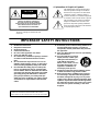 3
3
-
 4
4
-
 5
5
-
 6
6
-
 7
7
-
 8
8
-
 9
9
-
 10
10
-
 11
11
-
 12
12
-
 13
13
-
 14
14
-
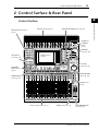 15
15
-
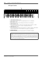 16
16
-
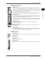 17
17
-
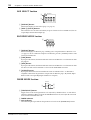 18
18
-
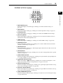 19
19
-
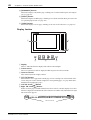 20
20
-
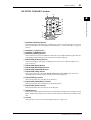 21
21
-
 22
22
-
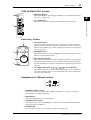 23
23
-
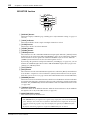 24
24
-
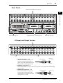 25
25
-
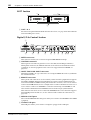 26
26
-
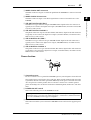 27
27
-
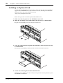 28
28
-
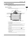 29
29
-
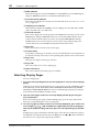 30
30
-
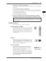 31
31
-
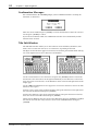 32
32
-
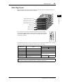 33
33
-
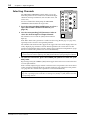 34
34
-
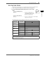 35
35
-
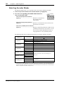 36
36
-
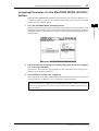 37
37
-
 38
38
-
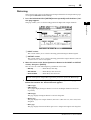 39
39
-
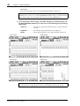 40
40
-
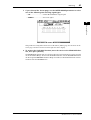 41
41
-
 42
42
-
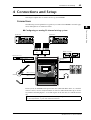 43
43
-
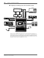 44
44
-
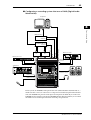 45
45
-
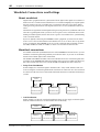 46
46
-
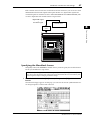 47
47
-
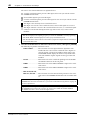 48
48
-
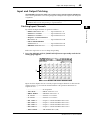 49
49
-
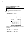 50
50
-
 51
51
-
 52
52
-
 53
53
-
 54
54
-
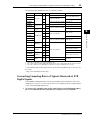 55
55
-
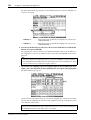 56
56
-
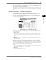 57
57
-
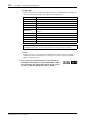 58
58
-
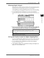 59
59
-
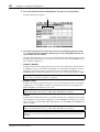 60
60
-
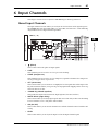 61
61
-
 62
62
-
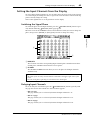 63
63
-
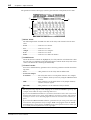 64
64
-
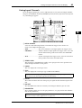 65
65
-
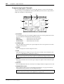 66
66
-
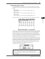 67
67
-
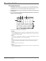 68
68
-
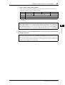 69
69
-
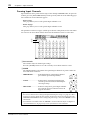 70
70
-
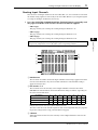 71
71
-
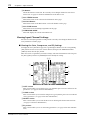 72
72
-
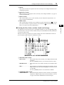 73
73
-
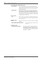 74
74
-
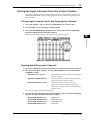 75
75
-
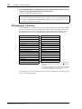 76
76
-
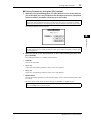 77
77
-
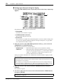 78
78
-
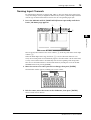 79
79
-
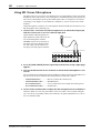 80
80
-
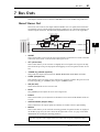 81
81
-
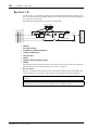 82
82
-
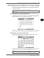 83
83
-
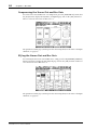 84
84
-
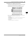 85
85
-
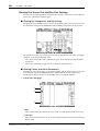 86
86
-
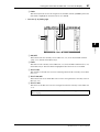 87
87
-
 88
88
-
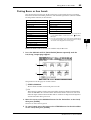 89
89
-
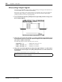 90
90
-
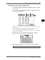 91
91
-
 92
92
-
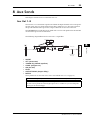 93
93
-
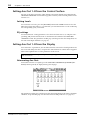 94
94
-
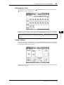 95
95
-
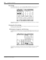 96
96
-
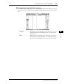 97
97
-
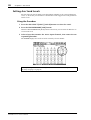 98
98
-
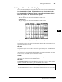 99
99
-
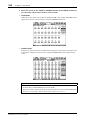 100
100
-
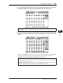 101
101
-
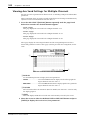 102
102
-
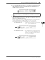 103
103
-
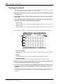 104
104
-
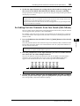 105
105
-
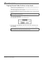 106
106
-
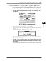 107
107
-
 108
108
-
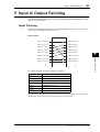 109
109
-
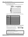 110
110
-
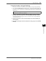 111
111
-
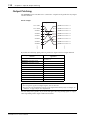 112
112
-
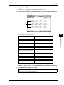 113
113
-
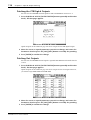 114
114
-
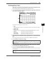 115
115
-
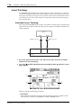 116
116
-
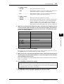 117
117
-
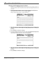 118
118
-
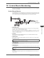 119
119
-
 120
120
-
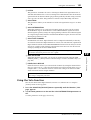 121
121
-
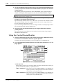 122
122
-
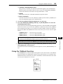 123
123
-
 124
124
-
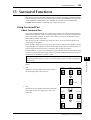 125
125
-
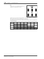 126
126
-
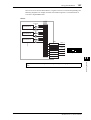 127
127
-
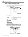 128
128
-
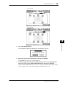 129
129
-
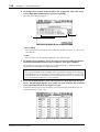 130
130
-
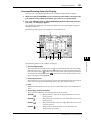 131
131
-
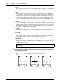 132
132
-
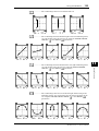 133
133
-
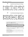 134
134
-
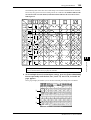 135
135
-
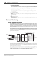 136
136
-
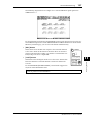 137
137
-
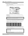 138
138
-
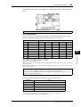 139
139
-
 140
140
-
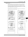 141
141
-
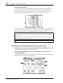 142
142
-
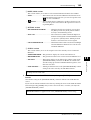 143
143
-
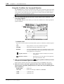 144
144
-
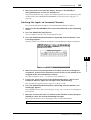 145
145
-
 146
146
-
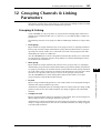 147
147
-
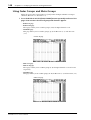 148
148
-
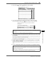 149
149
-
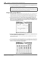 150
150
-
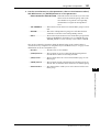 151
151
-
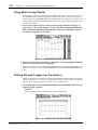 152
152
-
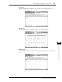 153
153
-
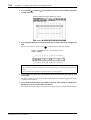 154
154
-
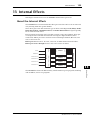 155
155
-
 156
156
-
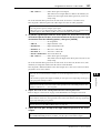 157
157
-
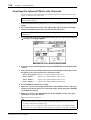 158
158
-
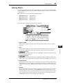 159
159
-
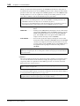 160
160
-
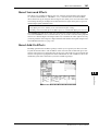 161
161
-
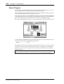 162
162
-
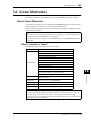 163
163
-
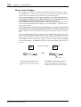 164
164
-
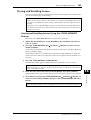 165
165
-
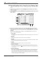 166
166
-
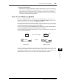 167
167
-
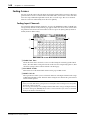 168
168
-
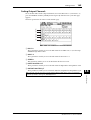 169
169
-
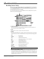 170
170
-
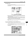 171
171
-
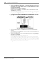 172
172
-
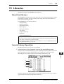 173
173
-
 174
174
-
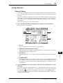 175
175
-
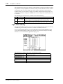 176
176
-
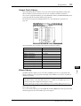 177
177
-
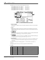 178
178
-
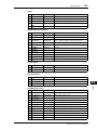 179
179
-
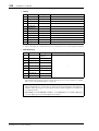 180
180
-
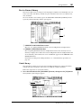 181
181
-
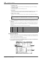 182
182
-
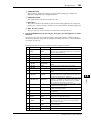 183
183
-
 184
184
-
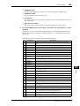 185
185
-
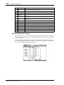 186
186
-
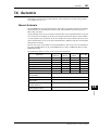 187
187
-
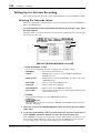 188
188
-
 189
189
-
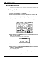 190
190
-
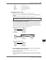 191
191
-
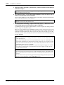 192
192
-
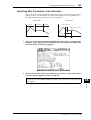 193
193
-
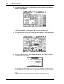 194
194
-
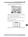 195
195
-
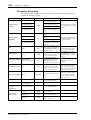 196
196
-
 197
197
-
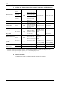 198
198
-
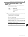 199
199
-
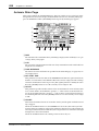 200
200
-
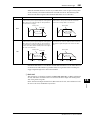 201
201
-
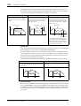 202
202
-
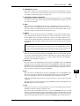 203
203
-
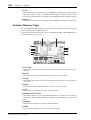 204
204
-
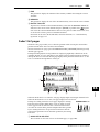 205
205
-
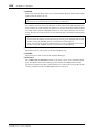 206
206
-
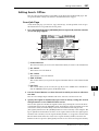 207
207
-
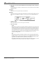 208
208
-
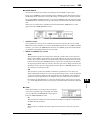 209
209
-
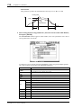 210
210
-
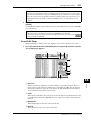 211
211
-
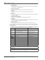 212
212
-
 213
213
-
 214
214
-
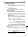 215
215
-
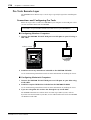 216
216
-
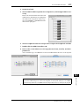 217
217
-
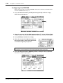 218
218
-
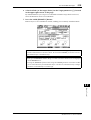 219
219
-
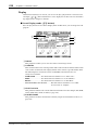 220
220
-
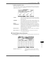 221
221
-
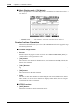 222
222
-
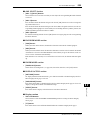 223
223
-
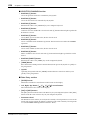 224
224
-
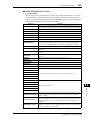 225
225
-
 226
226
-
 227
227
-
 228
228
-
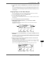 229
229
-
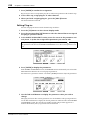 230
230
-
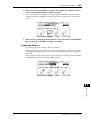 231
231
-
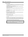 232
232
-
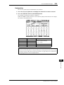 233
233
-
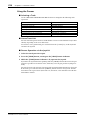 234
234
-
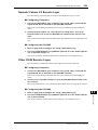 235
235
-
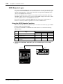 236
236
-
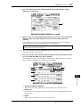 237
237
-
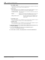 238
238
-
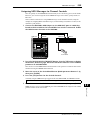 239
239
-
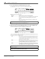 240
240
-
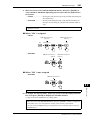 241
241
-
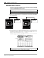 242
242
-
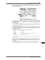 243
243
-
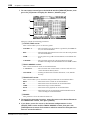 244
244
-
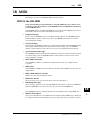 245
245
-
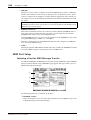 246
246
-
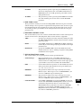 247
247
-
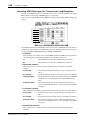 248
248
-
 249
249
-
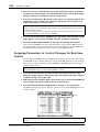 250
250
-
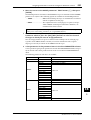 251
251
-
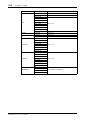 252
252
-
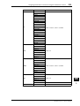 253
253
-
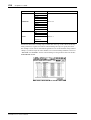 254
254
-
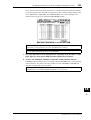 255
255
-
 256
256
-
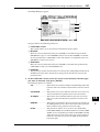 257
257
-
 258
258
-
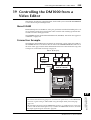 259
259
-
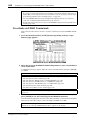 260
260
-
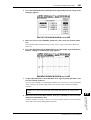 261
261
-
 262
262
-
 263
263
-
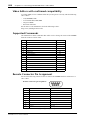 264
264
-
 265
265
-
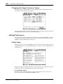 266
266
-
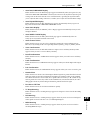 267
267
-
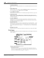 268
268
-
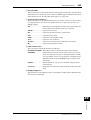 269
269
-
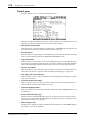 270
270
-
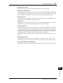 271
271
-
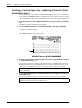 272
272
-
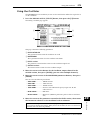 273
273
-
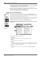 274
274
-
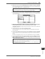 275
275
-
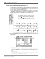 276
276
-
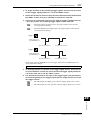 277
277
-
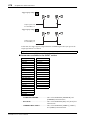 278
278
-
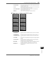 279
279
-
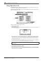 280
280
-
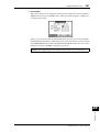 281
281
-
 282
282
-
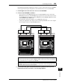 283
283
-
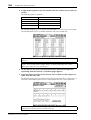 284
284
-
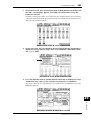 285
285
-
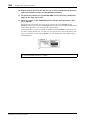 286
286
-
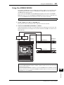 287
287
-
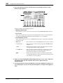 288
288
-
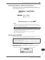 289
289
-
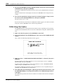 290
290
-
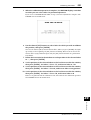 291
291
-
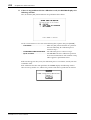 292
292
-
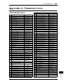 293
293
-
 294
294
-
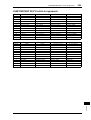 295
295
-
 296
296
-
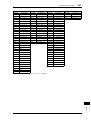 297
297
-
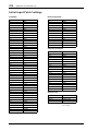 298
298
-
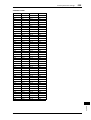 299
299
-
 300
300
-
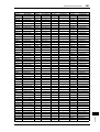 301
301
-
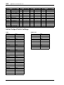 302
302
-
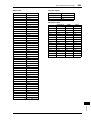 303
303
-
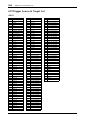 304
304
-
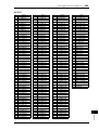 305
305
-
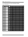 306
306
-
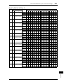 307
307
-
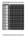 308
308
-
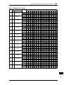 309
309
-
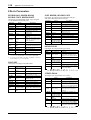 310
310
-
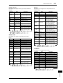 311
311
-
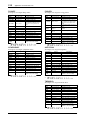 312
312
-
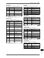 313
313
-
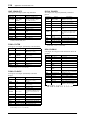 314
314
-
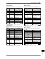 315
315
-
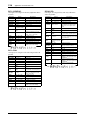 316
316
-
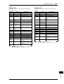 317
317
-
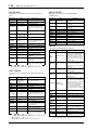 318
318
-
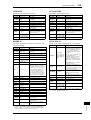 319
319
-
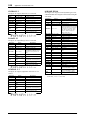 320
320
-
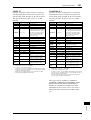 321
321
-
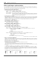 322
322
-
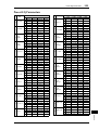 323
323
-
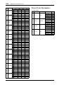 324
324
-
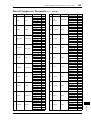 325
325
-
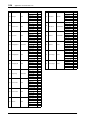 326
326
-
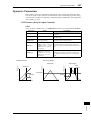 327
327
-
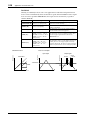 328
328
-
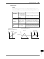 329
329
-
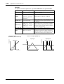 330
330
-
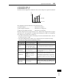 331
331
-
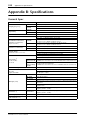 332
332
-
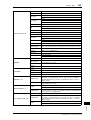 333
333
-
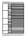 334
334
-
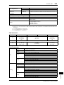 335
335
-
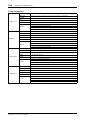 336
336
-
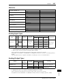 337
337
-
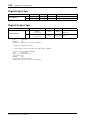 338
338
-
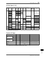 339
339
-
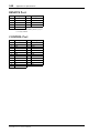 340
340
-
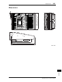 341
341
-
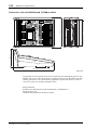 342
342
-
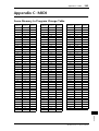 343
343
-
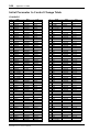 344
344
-
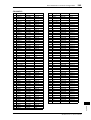 345
345
-
 346
346
-
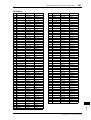 347
347
-
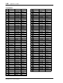 348
348
-
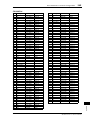 349
349
-
 350
350
-
 351
351
-
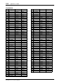 352
352
-
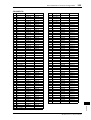 353
353
-
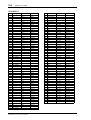 354
354
-
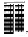 355
355
-
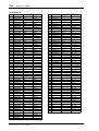 356
356
-
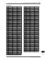 357
357
-
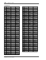 358
358
-
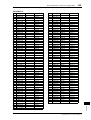 359
359
-
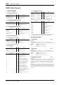 360
360
-
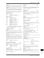 361
361
-
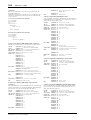 362
362
-
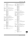 363
363
-
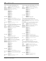 364
364
-
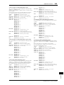 365
365
-
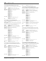 366
366
-
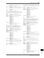 367
367
-
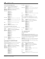 368
368
-
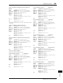 369
369
-
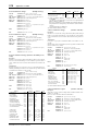 370
370
-
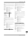 371
371
-
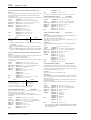 372
372
-
 373
373
-
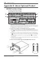 374
374
-
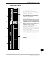 375
375
-
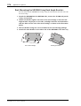 376
376
-
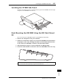 377
377
-
 378
378
-
 379
379
-
 380
380
-
 381
381
-
 382
382
-
 383
383
-
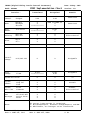 384
384
-
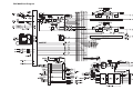 385
385
-
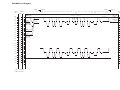 386
386
-
 387
387
-
 388
388


Yamaha 006IPTO-F0 Руководство пользователя
- Категория
- Дополнительное музыкальное оборудование
- Тип
- Руководство пользователя
Задайте вопрос, и я найду ответ в документе
Поиск информации в документе стал проще с помощью ИИ
на других языках
- English: Yamaha 006IPTO-F0 User manual
- français: Yamaha 006IPTO-F0 Manuel utilisateur
- italiano: Yamaha 006IPTO-F0 Manuale utente
- español: Yamaha 006IPTO-F0 Manual de usuario
- Deutsch: Yamaha 006IPTO-F0 Benutzerhandbuch
- Nederlands: Yamaha 006IPTO-F0 Handleiding
- português: Yamaha 006IPTO-F0 Manual do usuário
- dansk: Yamaha 006IPTO-F0 Brugermanual
- polski: Yamaha 006IPTO-F0 Instrukcja obsługi
- čeština: Yamaha 006IPTO-F0 Uživatelský manuál
- svenska: Yamaha 006IPTO-F0 Användarmanual
- Türkçe: Yamaha 006IPTO-F0 Kullanım kılavuzu
- suomi: Yamaha 006IPTO-F0 Ohjekirja
- română: Yamaha 006IPTO-F0 Manual de utilizare
Похожие модели бренда
-
Yamaha DM1000 Инструкция по применению
-
Yamaha 01V96i Руководство пользователя
-
-
-
-
Yamaha DM2000 Руководство пользователя
-
-
-
-