Sony DCR-PC115 Руководство пользователя
- Категория
- Видеокамеры
- Тип
- Руководство пользователя

Video camera
recorder
System
Video recording system
2 rotary heads
Helical scanning system
Audio recording system
Rotary heads, PCM system
Quantization: 12 bits (Fs 32 kHz,
stereo 1, stereo 2), 16 bits
(Fs 48 kHz, stereo)
Video signal
PAL colour, CCIR standards
NTSC color, EIA standards
DCR-PC115/PC120BT:
DCR-PC115E/PC120E:
Usable cassette
Mini DV cassette with the
mark printed
Tape speed
SP: Approx. 18.81 mm/s
LP: Approx. 12.56 mm/s
Recording/playback time (using
cassette DVM60)
SP: 1 hour
LP: 1.5 hours
Fastforward/rewind time (using
cassette DVM60)
When using the battery pack:
Approx. 2 min. and 30 seconds
When using the AC power adaptor:
Approx. 1 min. and 45 seconds
Viewfinder
Electric viewfinder (colour)
Image device
4.5 mm (1/4 type) CCD (Charge
Coupled Device)
Approx. 1 550 000 pixels
(Effective (moving): 970 000 pixels)
(Effective (still): 1 390 000 pixels)
Lens
Carl Zeiss Vario-Sonnar T*
Combined power zoom lens
Filter diameter: 37 mm (1 1/2 in)
10× (Optical), 120× (Digital)
Focal length
4.2 – 42 mm (3/16 – 1 11/16 in.)
When converted to a 35 mm still
camera
Camera mode:
48 – 480 mm (1 15/16 – 19 in.)
Memory mode:
40 – 400 mm (1 5/8 – 15 3/4 in.)
Colour temperature
Auto, HOLD (Hold),
Indoor
(3 200 K),
Outdoor (5 800 K)
Minimum illumination
7 lx (lux) (F 1.8)
0 lx (lux) (in the NightShot mode)*
* Objects unable to be seen due to
the dark can be shot with infrared
lighting.
Input/Output connectors
S video input/output
4-pin mini DIN
Luminance signal: 1 Vp-p,
75 Ω (ohms), unbalanced
Chrominance signal: 0.3 Vp-p,
DCR-PC115/PC120BT:
DCR-PC115E/PC120E:
75 Ω (ohms), unbalanced
Chrominance signal: 0.286 Vp-p,
75 Ω (ohms), unbalanced
Audio/Video input/output
AV MINI JACK, 1 Vp-p,
75 Ω (ohms), unbalanced, sync
negative
327 mV, (at output impedance
more than 47 kΩ (kilohms))
Output impedance with less than
2.2 kΩ (kilohms)/Stereo minijack
(ø 3.5 mm)
Input impedance more than
47 kΩ (kilohms)
DV input/output
4-pin connector
Headphone jack
Stereo minijack (ø 3.5 mm)
LANC jack
Stereo mini-minijack (ø 2.5 mm)
USB jack
mini-B
MIC jack
Minijack, 0.388 mV low impedance
with 2.5 to 3.0 V DC, output
impedance 6.8 kΩ (kilohms) (ø 3.5
mm)
Stereo type
SERVICE MANUALSERVICE MANUAL
DIGITAL VIDEO CAMERA RECORDER
SPECIFICATIONS
For MECHANISM ADJUSTMENTS, refer to the
“DV MECHANICAL ADJUSTMENT MANUAL
J MECHANISM ” (9-929-807-11).
— Continued on next page —
Level 2
On the VC-270 board
This service manual provides the information that is premised the
circuit board replacement service and not intended repair inside the
VC-270 board.
Therefore, schematic diagram, printed wiring board, waveforms, parts
location and electrical parts list of the VC-270 board are not shown.
The following pages are not shown.
Printed wiring board......................... Pages 4-19 to 4-22
Schematic diagram .......................... Pages 4-23 to 4-58
Waveforms and parts location ......... Pages 4-92 to 4-94
Electrical parts list............................ Pages 6-14 to 6-25
DCR-PC115/PC115E/
PC120BT/PC120E
RMT-811
Photo : DCR-PC120E
RMT-811
Canadian Model
DCR-PC120BT
AEP Model
DCR-PC115E/PC120E
UK Model
Australian Model
DCR-PC120E
E Model
DCR-PC115/PC115E/PC120E
Hong Kong Model
DCR-PC115/PC120E
Tourist Model
DCR-PC115/PC115E
Chinese Model
DCR-PC115E
Korea Model
DCR-PC115
NTSC model : DCR-PC115/PC120BT
PAL model : DCR-PC115E/PC120E
J MECHANISM
Ver 1.0 2001. 09

— 2 —
1. Check the area of your repair for unsoldered or poorly-soldered
connections. Check the entire board surface for solder splashes
and bridges.
2. Check the interboard wiring to ensure that no wires are
"pinched" or contact high-wattage resistors.
3. Look for unauthorized replacement parts, particularly
transistors, that were installed during a previous repair. Point
them out to the customer and recommend their replacement.
4. Look for parts which, through functioning, show obvious signs
of deterioration. Point them out to the customer and
recommend their replacement.
5. Check the B+ voltage to see it is at the values specified.
6. Flexible Circuit Board Repairing
• Keep the temperature of the soldering iron around 270˚C
during repairing.
• Do not touch the soldering iron on the same conductor of the
circuit board (within 3 times).
• Be careful not to apply force on the conductor when soldering
or unsoldering.
Unleaded solder
Boards requiring use of unleaded solder are printed with the lead-
free mark (LF) indicating the solder contains no lead.
(Caution: Some printed circuit boards may not come printed with
the lead free mark due to their particular size.)
: LEAD FREE MARK
Unleaded solder has the following characteristics.
• Unleaded solder melts at a temperature about 40°C higher than
ordinary solder.
Ordinary soldering irons can be used but the iron tip has to be
applied to the solder joint for a slightly longer time.
Soldering irons using a temperature regulator should be set to
about 350°C.
Caution: The printed pattern (copper foil) may peel away if the
heated tip is applied for too long, so be careful!
• Strong viscosity
Unleaded solder is more viscous (sticky, less prone to flow) than
ordinary solder so use caution not to let solder bridges occur such
as on IC pins, etc.
• Usable with ordinary solder
It is best to use only unleaded solder but unleaded solder may
also be added to ordinary solder.
SAFETY CHECK-OUT
After correcting the original service problem, perform the following
safety checks before releasing the set to the customer.
DCR-PC115/PC115E/PC120BT/PC120E
General
Power requirements
7.2 V (battery pack)
8.4 V (AC power adaptor)
Average power consumption
(when using the battery pack)
During camera recording using
LCD
4.1 W: DCR-PC115E/PC120E
4.4 W: DCR-PC115/PC120BT
Viewfinder
3.6 W: DCR-PC115E/PC120E
3.8 W: DCR-PC115/PC120BT
Operating temperature
0°C to 40°C (32°F to 104°F)
Storage temperature
–20°C to +60°C
(–4°F to +140°F)
Dimensions (Approx.)
57 × 118 × 113 mm
(2 1/4 × 4 3/4 × 4 1/2 in.)
(w/h/d)
Mass (approx.)
580 g (1 lb 4 oz)
main unit only
690 g (1 lb 8 oz)
including the battery pack
NP-FM50, cassette DVM60 and lens
cap
Supplied accessories
See page 3.
AC power adaptor
Power requirements
100 – 240 V AC, 50/60 Hz
Power consumption
23 W
Output voltage
DC OUT: 8.4 V, 1.5 A in the
operating mode
Operating temperature
0°C to 40°C (32°F to 104°F)
Storage temperature
–20°C to + 60°C (–4°F to + 140°F)
Dimensions (approx.)
125 × 39 × 62 mm
(5 × 1 9/16 × 2 1/2 in.) (w/h/d)
excluding projecting parts
Mass (approx.)
280 g (9.8 oz)
excluding power cord
Battery pack
Maximum output voltage
DC 8.4 V
Output voltage
DC 7.2 V
Capacity
8.5 Wh (1 180 mAh)
Dimensions (approx.)
38.2 × 20.5 × 55.6 mm
(1 9/16 × 13/16 × 2 1/4 in.)
(w/h/d)
Mass (approx.)
76 g (2.7 oz)
Type
Lithium ion
“Memory Stick”
Memory
Flash memory
8MB: MSA-8A
Operating voltage
2.7 – 3.6 V
Power consumption
Approx. 45 mA in the operating
mode
Approx. 130 µA in the standby
mode
Dimensions (approx.)
50 × 2.8 × 21.5 mm
(2 × 1/8 × 7/8 in.) (w/h/d)
Mass (approx.)
4 g (0.14 oz)
Design and specifications are
subject to change without notice.
Wireless communications
(DCR-PC120BT/PC120E only)
Communications system
Bluetooth standard Ver.1.1
Max. baud rate
1) 2)
Approx. 723 kbps
Output
Bluetooth standard Power Class 2
Communications distance
2)
Max. wireless distance Approx. 10 m
(393 3/4 in.) (When connecting to
BTA-NW1 (optional))
Compatible Bluetooth profile
3)
Generic Access Profile
Dial-up Networking Profile
Operating frequency band
2.4 GHz band (2.400 GHz-
2.483 5 GHz)
1) Max. baud rate of Bluetooth
standard Ver.1.1
2) Varies according to the distance
between communicating devices,
presence of obstacles, radiowave
conditions, and other factors.
3) This is a specification matched to
specific usage requirements
between Bluetooth compatible
devices. It is laid down in the
Bluetooth standards.
LCD screen
Picture
6.2 cm (2.5 type)
50 × 37 mm (2 × 1 1/2 in.)
Total dot number
211 200 (960 × 220)

— 3 —
DCR-PC115/PC115E/PC120BT/PC120E
• SUPPLIED ACCESSORIES
Make sure that the following accessories are supplied with your camcorder.
• Abbreviation
CND : Canadian model
HK : Hong Kong model
AUS : Australian model
CN : Chinese model
JE : Tourist model
KR : Korea model
Table for difference of functions
DCR-
Destination
Color system
NETWORK (Bluetooth)
Flash memory
(VC-270 board IC1406)
SDRAM
(VC-270 board IC1404)
BT-003 board
PC115
E, HK, KR,
JE
NTSC
✕
4Mbit
16Mbit
✕
PC115E
AEP, E, JE,
CN
PAL
✕
4Mbit
16Mbit
✕
PC120BT
CND
NTSC
a
32Mbit
64Mbit
a
PC120E
AEP, UK,
E, AUS, HK
PAL
a
32Mbit
64Mbit
a
Remarks
NTSC: X301 of VC-270 board is 54MHz.
PAL: X301 of VC-270 board is 40.5MHz.
With BT-003 board
8
1
9
0
qd qf
4567
qa
23
qs
1
2
AC-L10A/L10B/L10C AC power adaptor (1),
mains lead (1)
A/V connecting cable (1)
3 USB cable (1)
4 Battery terminal cover (1)
5 NP-FM50 battery pack (1)
6 Wireless Remote Commander (1)
7 Size R6 (AA) battery for Remote
Commander (2)
8 Lens cap (1)
9 Lens hood (1)
0 Memory Stick (MSA-8A) (1)
qa CD-ROM (SPVD-004 USB Driver) (1)
qs 21-pin adaptor (1)
DCR-PC115E/PC120E only
qd 2-pin conversion adaptor (1)
DCR-PC115: JE/PC115E: JE only
qf 2-pin conversion adaptor (1)
DCR-PC115: E,HK/PC115E: E/
PC120E: E, HK only

— 4 —
DCR-PC115/PC115E/PC120BT/PC120E
TABLE OF CONTENTS
SERVICE NOTE
1. POWER SUPPLY DURING REPAIRS ····························· 7
2. TO TAKE OUT A CASSETTE WHEN NOT EJECT
(FORCE EJECT) ································································ 7
3. DISCHARGING OF THE FLASHLIGHT POWER
SUPPLY CAPACITOR ······················································ 8
3-1. DISCHARGING THE CAPACITOR USING
THE SHORT JIG································································ 8
3-1-1.PREPARING THE SHORT JIG ········································· 8
3-1-2.DISCHARGING THE CAPACITOR································· 8
3-2. DISCHARGING THE CAPACITOR USING THE
REMOTE COMMANDER ················································8
3-2-1.DISCHARGING THE CAPACITOR································· 8
3-2-2.PROCESSING AFTER COMPLETING REPAIRS/
ADJUSTMENTS································································ 8
SELF-DIAGNOSIS FUNCTION
1. SELF-DIAGNOSIS FUNCTION·······································9
2. SELF-DIAGNOSIS DISPLAY ·········································· 9
3. SERVICE MODE DISPLAY ············································· 9
3-1. Display Method ·································································· 9
3-2. Switching of Backup No. ··················································· 9
3-3. End of Display···································································· 9
4. SELF-DIAGNOSIS CODE TABLE································· 10
1. GENERAL
Main Features ············································································1-1
Quick Start Guide ······································································1-1
Getting started
Using this manual ··································································1-2
Checking supplied accessories ··············································1-2
Step 1 Preparing the power supply ········································1-3
Installing the battery pack···················································1-3
Charging the battery pack ···················································1-3
Connecting to a wall socket ················································1-4
Step 2 Setting the date and time ············································1-4
Step 3 Inserting a cassette······················································1-5
Recording – Basics
Recording a picture································································1-5
Shooting backlit subjects – BACK LIGHT ···························1-8
Shooting in the dark – NightShot/Super NightShot ··············1-8
Self-timer recording·······························································1-8
Checking the recording – END SEARCH / EDITSEARCH /
Rec Review ·········································································1-9
Playback – Basics
Playing back a tape ································································1-9
To display the screen indicators – Display function ··············1-9
Viewing the recording on TV ··············································1-10
Advanced Recording Operations
Recording a still image on a tape – Tape Photo recording ··1-11
Adjusting the white balance manually·································1-12
Using the wide mode ···························································1-13
Using the fader function ······················································1-13
Using special effects – Picture effect ···································1-14
Using special effects – Digital effect ···································1-14
Using the PROGRAM AE function·····································1-15
Adjusting the exposure manually ········································1-16
Focusing manually·······························································1-16
Interval recording·································································1-17
Frame by frame recording – Cut recording ·························1-17
Advanced Playback Operations
Playing back a tape with picture effects ······························1-18
Playing back a tape with digital effects ·······························1-18
Enlarging images recorded on tapes – Tape PB ZOOM ······1-18
Quickly locating a scene using the zero set memory function ··
1-19
Searching the boundaries of recorded tape by title
– Title search·····································································1-19
Searching a recording by date – Date search·······················1-20
Searching for a photo – Photo search/Photo scan················1-20
Editing
Dubbing a tape ·····································································1-21
Dubbing only desired scenes
– Digital program editing (on tapes)·································1-22
Using with analog video unit and your computer
– Signal convert function ··················································1-25
Recording video or TV programmes ···································1-26
Inserting a scene from a VCR – Insert editing·····················1-27
Audio dubbing ·····································································1-28
Superimposing a title ···························································1-29
Making your own titles ························································1-30
Labelling a cassette······························································1-30
Customising Your Camcorder
Changing the menu settings·················································1-31
“Memory Stick” Operations
Using a “Memory Stick” – introduction ······························1-33
Recording still images on “Memory Stick”s
– Memory Photo recording ···············································1-36
Recording an image from a tape as a still image ·················1-38
Superimposing a still image in the “Memory Stick” on an
image – MEMORY MIX ··················································1-39
Recording moving pictures on “Memory Stick”s
– MPEG movie recording ·················································1-41
Recording a picture from a tape as a moving picture ··········1-41
Recording edited pictures as a moving picture
– Digital program editing (on “Memory Stick”s)·············1-42
Copying still images from a tape – Photo save····················1-43
Viewing a still image – Memory photo playback ················1-44
Viewing a moving picture – MPEG movie playback ··········1-45
Viewing images using computer··········································1-45
Copying the image recorded on “Memory Stick”s to tapes ·
1-47
Enlarging still images recorded on “Memory Stick”s
– Memory PB ZOOM ·······················································1-48
Playing back images in a continuous loop – SLIDE SHOW··
1-48
Preventing accidental erasure – Image protection ···············1-49
Deleting images ···································································1-49
Writing a print mark – PRINT MARK································1-49
Using the optional printer ····················································1-50
Using the Network function
Accessing the network ·························································1-50
Troubleshooting
Types of trouble and their solutions·····································1-51
Self-diagnosis display ··························································1-52
Warning indicators and messages ········································1-52
Additional Information
Usable cassettes ···································································1-53
About the “InfoLITHIUM” battery pack·····························1-54
About i.LINK·······································································1-54
Using your camcorder abroad··············································1-55
Maintenance information and precautions···························1-55
Quick Reference
Identifying the parts and controls ········································1-57
2. DISASSEMBLY
2-1. LCD CABINET (R) ASSEMBLY···································2-3
2-2. CABINET (L) SECTION················································2-4
2-3. VTR COMPLETE, CABINET (R) SECTION ···············2-6
2-4. FJ-035 BOARD ·······························································2-7
2-5. VM-027 BOARD ····························································2-8
2-6. CD-349 BOARD, LENS DEVICE··································2-8
2-7. VC-270 BOARD ·····························································2-9
2-8. MECHANISM DECK·····················································2-9
2-9. FLASH UNIT (MC) ······················································2-10
2-10. FLASH UNIT (ST) ·······················································2-10
2-11. CABINET (G) BLOCK ASSEMBLY, ETC.·················2-11

— 5 —
DCR-PC115/PC115E/PC120BT/PC120E
2-12. CONTROL SWITCH BLOCK (FK-1850) ···················2-12
2-13. CONTROL SWITCH BLOCK (PS-1850) ····················2-12
2-14. BLIND PLATE ASSEMBLY ········································2-13
2-15. PD-148B BOARD, INVERTER TRANSFORMER
UNIT ·············································································2-13
2-16. HINGE ASSEMBLY ·····················································2-14
2-17. CIRCUIT BOARDS LOCATION ·································2-18
2-18. FLEXIBLE BOARDS LOCATION ······························2-19
3. BLOCK DIAGRAMS
3-1. OVERALL BLOCK DIAGRAM (1/4) ···························3-1
3-2. OVERALL BLOCK DIAGRAM (2/4) ···························3-3
3-3. OVERALL BLOCK DIAGRAM (3/4) ···························3-5
3-4. OVERALL BLOCK DIAGRAM (4/4) ···························3-7
3-5. POWER BLOCK DIAGRAM (1/3) ································3-9
3-6. POWER BLOCK DIAGRAM (2/3) ······························3-11
3-7. POWER BLOCK DIAGRAM (3/3) ······························3-13
4. PRINTED WIRING BOARDS AND
SCHEMATIC DIAGRAMS
4-1. FRAME SCHEMATIC DIAGRAM (1/3) ·······················4-1
FRAME SCHEMATIC DIAGRAM (2/3) ·······················4-3
FRAME SCHEMATIC DIAGRAM (3/3) ·······················4-5
4-2. PRINTED WIRING BOARDS AND
SCHEMATIC DIAGRAMS ············································4-8
• CD-349 (CCD IMAGER)
SCHEMATIC DIAGRAM ······························4-9
• CD-349 (CCD IMAGER)
PRINTED WIRING BOARD ·······················4-11
• FP-386 (REMOTE COMMANDER RECEIVER)
PRINTED WIRING BOARD AND
SCHEMATIC DIAGRAM ····························4-15
• FP-383 (MEMORY STICK CONNECTOR)
SCHEMATIC DIAGRAM ····························4-17
• CONTROL SWITCH BLOCK (ME-1850)
SCHEMATIC DIAGRAM ····························4-18
Shematic diagram and printed wiring board of the
VC-270 board are not shown.
Pages from 4-19 to 4-58 are not shown.
• FP-100 (MODE SWITCH), FP-228 (DEW SENSOR),
FP-102 (TAPE TOP/END SENSOR, S/T REEL)
FLEXIBLE BOARDS··································4-59
• VM-027 (RGB DRIVE, TIMING GENERATOR)(1/3)
SCHEMATIC DIAGRAM ····························4-61
• VM-027 (MIC AMP)(2/3)
SCHEMATIC DIAGRAM ····························4-63
• VM-027 (CONNECTOR)(3/3)
SCHEMATIC DIAGRAM ····························4-65
• VM-027 (RGB DRIVE, TIMING GENERATOR,
MIC AMP)
PRINTED WIRING BOARD ·······················4-67
• FLASH UNIT (MC-1850)
SCHEMATIC DIAGRAM ····························4-71
• FLASH UNIT (ST-1850)
SCHEMATIC DIAGRAM ····························4-73
• CONTROL SWITCH BLOCK (PS-1850)
SCHEMATIC DIAGRAM ····························4-74
• KY-060 (USER FUNCTION)
PRINTED WIRING BOARD ·······················4-76
• KY-060 (USER FUNCTION)
SCHEMATIC DIAGRAM ····························4-77
• CONTROL SWITCH BLOCK (FK-1850)
PRINTED WIRING BOARD ·······················4-80
• CONTROL SWITCH BLOCK (FK-1850)
SCHEMATIC DIAGRAM ····························4-81
• FJ-035 (DC-IN, CHARGE)
PRINTED WIRING BOARD ·······················4-83
• FJ-035 (DC-IN, CHARGE)
SCHEMATIC DIAGRAM ····························4-85
• FP-387 (PANEL OPEN/CLOSE)
SCHEMATIC DIAGRAM ····························4-86
• PD-148 (RGB DRIVE, TIMING GENERATOR)
PRINTED WIRING BOARD ·······················4-87
• PD-148 (RGB DRIVE, TIMING GENERATOR)
SCHEMATIC DIAGRAM ····························4-89
4-3. WAVEFORMS ······························································4-91
Waveforms and parts location of the VC-270 board
are not shown.
Pages from 4-92 to 4-94 are not shown.
4-4. MOUNTED PARTS LOCATION ·································4-95
5. ADJUSTMENTS
1.
Adjusting items when replacing main parts and boards.··
5-2
5-1. CAMERA SECTION ADJUSTMENT ···························5-4
1-1. PREPARATIONS BEFORE ADJUSTMENT
(CAMERA SECTION) ···················································5-4
1-1-1.List of Service Tools························································5-4
1-1-2.Preparations ·····································································5-5
1-1-3.Precaution········································································5-7
1. Setting the Switch····························································5-7
2. Order of Adjustments ······················································5-7
3. Subjects ···········································································5-7
1-2.
INITIALIZATION OF B, C, D, E, F, 7, 8 PAGE DATA ··
5-8
1-2-1.INITIALIZATION OF C, D, 8 PAGE DATA ··················5-8
1. Initializing the C, D, 8 Page Data····································5-8
2. Modification of C, D, 8 Page Data ··································5-8
3. C Page Table ····································································5-8
4. D Page Table··································································5-10
5. 8 Page Table···································································5-11
1-2-2.INITIALIZATION OF B PAGE DATA
(DCR-PC120BT/PC120E) ············································5-12
1. Initializing the B Page Data···········································5-12
2. Modification of B Page Data ·········································5-12
3. Writing the Network Default Setting Value ··················5-12
4. B Page Table ··································································5-12
1-2-3.INITIALIZATION OF E, F, 7 PAGE DATA ·················5-13
1. Initializing the E, F, 7 Page Data ···································5-13
2. Modification of E, F, 7 Page Data ·································5-13
3. F Page Table ··································································5-13
4. E Page Table ··································································5-15
5. 7 Page Table···································································5-15
1-3. CAMERA SYSTEM ADJUSTMENTS ························5-16
1. 40.5MHz/54MHz Origin Oscillation Adjustment
(VC-270 board) ·····························································5-16
2. MR Adjustment ·····························································5-16
3. HALL Adjustment ·························································5-17
4. MAX GAIN Adjustment ···············································5-18
5. CCD Output 2ch Matching Adjustment ························5-18
5-1. CCD Output 2ch Matching Adjustment (1) ··················5-18
5-2. CCD Output 2ch Matching Adjustment (2) ··················5-19
5-3. CCD Output 2ch Matching Adjustment (3) ··················5-21
5-4. CCD Output 2ch Matching Adjustment (4) ··················5-21
5-5. CCD Output 2ch Matching Adjustment (5) ··················5-23
6. Flange Back Adjustment (Using Minipattern Box)·······5-24
7. Flange Back Adjustment (Using Flange Back Adjustment
Chart and Subject More Than 500m Away) ··················5-25
7-1. Flange Back Adjustment (1) ··········································5-25
7-2. Flange Back Adjustment (2) ··········································5-25
8. Flange Back Check························································5-26
9. Picture Frame Setting ····················································5-26

— 6 —
DCR-PC115/PC115E/PC120BT/PC120E
10. Color Reproduction Adjustment····································5-27
11. Auto White Balance & LV Standard Data Input ···········5-28
12. Auto White Balance Adjustment ···································5-29
13. White Balance Check ····················································5-30
14. Mechanical Shutter Adjustment ····································5-31
15. Steady Shot Check·························································5-31
16. Strobe Light Level Adjustment ·····································5-32
17. Strobe White Balance Adjustment & Check ·················5-33
18. AF Laser Output Adjustment ········································5-34
19. AF Laser Optical Axis Adjustment ·······························5-35
1-4. COLOR ELECTRONIC VIEWFINDER SYSTEM
ADJUSTMENT·····························································5-36
1. VCO Adjustment (VM-027 board)································5-36
2. Backlight Adjustment (VM-027 board) ························5-37
3. Bright Adjustment (VM-027 board) ······························5-37
4. Contrast Adjustment (VM-027 board) ··························5-38
5. White Balance Adjustment (VM-027 board) ················5-38
1-5. LCD SYSTEM ADJUSTMENT ···································5-39
1. VCO Adjustment (PD-148 board) ·································5-39
2. Bright Adjustment (PD-148 board) ·······························5-40
3. Black Limit Adjustment (PD-148 board) ······················5-40
4. PSIG GRAY Adjustment (PD-148 board) ·····················5-41
5. Contrast Adjustment (PD-148 board) ····························5-41
6. Center Level Adjustment (PD-148 board)·····················5-42
7. V-COM Adjustment (PD-148 board) ····························5-42
8. White Balance Adjustment (PD-148 board)··················5-43
5-2. MECHANISM SECTION ADJUSTMENT··················5-44
2-1. HOW TO ENTER RECORD MODE WITHOUT
CASSETTE ···································································5-44
2-2. HOW TO ENTER PLAYBACK MODE WITHOUT
CASSETTE ···································································5-44
2-3. TAPE PATH ADJUSTMENT········································5-44
1. Preparation for Adjustment ···········································5-44
2. Procedure after operations·············································5-44
5-3. VIDEO SECTION ADJUSTMENTS ···························5-45
3-1. PREPARATIONS BEFORE ADJUSTMENTS ············5-45
3-1-1.Equipment Required ······················································5-45
3-1-2.Precautions on Adjusting ···············································5-46
3-1-3.Adjusting Connectors ····················································5-47
3-1-4.Connecting the Equipment ············································5-47
3-1-5.Alignment Tapes····························································5-48
3-1-6.Input/Output Level and Impedance ·······························5-48
3-2. SYSTEM CONTROL SYSTEM ADJUSTMENT········5-49
1. Initialization of B, C, D, E, F, 7, 8 Page Data ···············5-49
2. Serial No. Input ·····························································5-49
2-1. Company ID Input·························································5-49
2-2. Serial No. Input ·····························································5-49
3-3. SERVO AND RF SYSTEM ADJUSTMENT ···············5-51
1. Cap FG Duty Adjustment (VC-270 board) ···················5-51
2. PLL f
0 & LPF f0 Adjustment (VC-270 board) ··············5-51
3. Switching Position Adjustment (VC-270 board)···········5-52
4. AGC Center Level and APC & AEQ Adjustment ·········5-52
4-1. Preparations before adjustments····································5-52
4-2. AGC Center Level Adjustment (VC-270 board) ···········5-53
4-3. APC & AEQ Adjustment (VC-270 board) ····················5-53
4-4. Processing after Completing Adjustments ····················5-54
5. PLL f0 & LPF f0 Fine Adjustment (VC-270 board) ······5-54
3-4. VIDEO SYSTEM ADJUSTMENTS·····························5-55
1. Chroma BPF f0 Adjustment (VC-270 board) ················5-55
2. S VIDEO OUT Y Level Adjustment (VC-270 board)···5-55
3. S VIDEO OUT Chroma Level Adjustment
(VC-270 board) ·····························································5-56
4.
VIDEO OUT Y, Chroma Level Check (VC-270 board) ··
5-56
3-5. AUDIO SYSTEM ADJUSTMENTS ····························5-57
1. Playback Level Check ···················································5-58
2. Overall Level Characteristics Check ·····························5-58
3. Overall Distortion Check···············································5-58
4. Overall Noise Level Check············································5-58
5. Overall Separation Check ··············································5-58
5-4. SERVICE MODE ··························································5-59
4-1. ADJUSTMENT REMOTE COMMANDER ················5-59
1. Using the adjustment remote commander ·····················5-59
2. Precautions upon using the adjustment remote
commander ····································································5-59
4-2. DATA PROCESS···························································5-60
4-3. SERVICE MODE ··························································5-61
1. Setting the Test Mode ····················································5-61
2. Emergence Memory Address ········································5-61
2-1. EMG Code (Emergency Code) ·····································5-61
2-2. MSW Code ····································································5-62
3. Bit value discrimination ················································5-63
4. Switch check (1)····························································5-63
5. Switch check (2)····························································5-63
6. Switch check (3)····························································5-63
7. Switch check (4)····························································5-64
8. Record of Use check······················································5-65
9. Record of Self-diagnosis check·····································5-65
6. REPAIR PARTS LIST
6-1. EXPLODED VIEWS ······················································6-1
6-1-1.OVERALL SECTION·····················································6-1
6-1-2.CABINET (L) SECTION················································6-2
6-1-3.VTR OVERALL SECTION············································6-3
6-1-4.LENS-EVF SECTION ····················································6-4
6-1-5.CABINET (R) SECTION-1 ············································6-5
6-1-6.CABINET (R) SECTION-2 ············································6-6
6-1-7.CASSETTE COMPARTMENT AND DRUM BLOCK
ASSEMBLY ····································································6-7
6-1-8.LS CHASSIS BLOCK ASSEMBLY·······························6-8
6-1-9.MECHANISM CHASSIS BLOCK ASSEMBLY ···········6-9
6-2. ELECTRICAL PARTS LIST ········································6-10
Parts list of the VC-270 board are not shown.
Pages from 6-14 to 6-25 are not shown.
* Color reproduction frame is shown on page 241.

— 7 —
DCR-PC115/PC115E/PC120BT/PC120E
SERVICE NOTE
1. POWER SUPPLY DURING REPAIRS
In this unit, about 10 seconds after power is supplied to the battery terminal using the regulated power supply (8.4V), the power is shut off so
that the unit cannot operate.
This following two methods are available to prevent this. Take note of which to use during repairs.
Method 1
Use the AC power adaptor (AC-L10, AC-VQ800, AC-SQ950 etc.).
Method 2
Connect the servicing remote commander RM-95 (J-6082-053-B) to the LANC jack, and set the commander switch to the “ADJ” side.
2. TO TAKE OUT A CASSETTE WHEN NOT EJECT (FORCE EJECT)
1 Refer to 2-2. to remove the HS cover.
2 Refer to 2-2. to remove the jack cover.
3 Refer to 2-2. to remove the cabinet (R) assembly.
4 Refer to “3. DISCHARGING OF THE FLASHLIGHT POWER SUPPLY CAPACITOR” to discharge the flash power supply capacitor.
5 Refer to 2-3. to remove the mechanism deck and the lens block and the EVF block from the cabinet (L) block.
6 Disconnect CN302 (72P, 0.4mm) of VC-270 board.
7 Disconnect CN006 (27P, 0.3mm) of VC-270 board.
8 Supply +4.5V from the DC power supply to the loading motor and unload with a pressing the cassette compartment.
: Unloading
: Loading
VC-270 board
Loading motor
Regulated power supply
(+4.5Vdc)
CN006
CN302

— 8 —
DCR-PC115/PC115E/PC120BT/PC120E
3. DISCHARGING OF THE FLASHLIGHT POWER SUPPLY CAPACITOR
The capacitor (C2010) of the flash unit (MC1850) is charged up to the maximum 300V potential. There is a danger of electric shock by this
high voltage when the flash unit (MC1850 or ST1850) is handled by hand. The electric shock is caused by the charged voltage which is kept
without discharging when the main power of the unit is simply turned off. Therefore, the remaining voltage must be discharged as described
below.
3-1. DISCHARGING THE CAPACITOR USING THE SHORT JIG
3-1-1. PREPARING THE SHORT JIG
To preparing the short jig. a small clip is attached to each end of a resistor of 1kΩ/1W (1-215-869-11). Wrap insulating tape fully around the
reads of the resistor to prevent electric shock.
3-1-2. DISCHARGING THE CAPACITOR
Connect the short jig with the capacitor directly.
1 Remove the power supply (Battery or AC power adaptor).
2 Short circuit between TP001 of the flash unit (MC1850) and the GND
(Chassis etc.) with the short jig about 10 seconds.
3-2. DISCHARGING THE CAPACITOR USING THE REMOTE COMMANDER
3-2-1. DISCHARGING THE CAPACITOR
Note: Perfect discharge can’t be done in this method. (Remaining voltage = Approx. 90V)
1 Connect the power supply (Battery or AC power adaptor).
2 Set POWER switch to “CAMERA”.
3 Connect the adjustment remote commander to the LANC jack, and set the HOLD switch to the “ADJ” side.
4 Select page: 0, address: 01. and set data: 01.
5 Select page: D, address: F4. set data: 04, and press PAUSE button of the adjustment remote commander.
6 Press FLASH ( ) button and set to the forced flash mode ( ), and press PHOTO button to pop up the flash.
7 Select page: 6, address: B3. and set data: 03.
8 Select page: 6, address: B1. and set data: 01.
9 Select page: 6, address: B0. and set data: 01.
→The flash flashes, and data are returned to “00”
0 Repeat step 9, until the flash dose not flash.
After completing repairs/adjustments, perform “PROCESSING AFTER COMPLETING REPAIRS/ADJUSTMENTS”
3-2-2. PROCESSING AFTER COMPLETING REPAIRS/ADJUSTMENTS
1 Connect the power supply (Battery or AC power adaptor).
2 Set POWER switch to “CAMERA”.
3 Connect the adjustment remote commander to the LANC jack, and set the HOLD switch to the “ADJ” side.
4 Select page: 0, address: 01. and set data: 01.
5 Select page: D, address: F4. set data: 00, and press PAUSE button of the adjustment remote commander.
6 Select page: 6, address: B3. and set data: 00.
7 Select page: 6, address: B1. and set data: 00.
8 Select page: 0, address: 01. and set data: 00.
1 k
Ω
/1 W
Wrap insulating tape
Flash unit
(MC1850) TP001
Flash unit (MC1850)
C2010
Short jig
GND
Chassis
(Sheet metal bending block)
1 k
Ω
/1 W resistor
(1-215-869-11)

— 9 —
DCR-PC115/PC115E/PC120BT/PC120E
SELF-DIAGNOSIS FUNCTION
1. SELF-DIAGNOSIS FUNCTION
When problems occur while the unit is operating, the self-diagnosis
function starts working, and displays on the viewfinder or LCD
screen what to do. This function consists of two display; self-
diagnosis display and service mode display.
Details of the self-diagnosis functions are provided in the Instruction
manual.
Note: The “self-diagnosis display” data will be backed up by the coin-type lithium battery (BT001) of the control switch block (FK-1850). When the
cabinet (L) assembly is removed, the “self-diagnosis display” data will be lost by initialization.
2. SELF-DIAGNOSIS DISPLAY
When problems occur while the unit is operating, the counter of the
viewfinder or LCD screen consists of an alphabet and 4-digit
numbers, which blinks at 3.2 Hz. This 5-character display indicates
the “repaired by:”, “block” in which the problem occurred, and
“detailed code” of the problem.
3. SERVICE MODE DISPLAY
The service mode display shows up to six self-diagnosis codes shown in the past.
3-1. Display Method
While pressing the “STOP” key, set the switch from OFF to “VCR”, and continue pressing the “STOP” key for 5 seconds continuously. The
service mode will be displayed, and the counter will show the backup No. and the 5-character self-diagnosis codes.
3-2. Switching of Backup No.
By pressing up side or down side of the control button, past self-diagnosis codes will be shown in order. The backup No. in the [] indicates the
order in which the problem occurred. (If the number of problems which occurred is less than 6, only the number of problems which occurred
will be shown.)
[1] : Occurred first time [4] : Occurred fourth time
[2] : Occurred second time [5] : Occurred fifth time
[3] : Occurred third time [6] : Occurred the last time
3-3. End of Display
Turning OFF the power supply will end the service mode display.
Order of previous errors
Backup No.
Self-diagnosis Codes
C : 3 1 : 1 1
[3]
Lights up
Viewfinder or LCD screen
[3] C : 3 1 : 1 1
1 1
3 1C
Repaired by:
Refer to page 10.
Self-diagnosis Code Table.
Indicates the appropriate
step to be taken.
E.g.
31 ....Reload the tape.
32 ....Turn on power again.
Block
Detailed Code
Blinks at 3.2Hz
C : Corrected by customer
H : Corrected by dealer
E : Corrected by service
engineer
Viewfinder or LCD screen
C : 3 1 : 1 1
Control button

— 10 —
DCR-PC115/PC115E/PC120BT/PC120E
4. SELF-DIAGNOSIS CODE TABLE
C
C
C
C
C
C
C
C
C
C
C
C
C
C
C
C
C
C
C
C
C
C
C
E
E
E
E
E
Block
Function
04
21
22
31
31
31
31
31
31
31
31
31
31
31
31
32
32
32
32
32
32
32
32
61
61
62
62
91
Detailed
Code
00
00
00
10
11
20
21
22
23
24
30
40
42
10
11
20
21
22
23
24
30
40
42
00
10
00
01
01
Symptom/State
Non-standard battery is used.
Condensation.
Video head is dirty.
LOAD direction. Loading does not
complete within specified time
UNLOAD direction. Loading does not
complete within specified time
T reel side tape slacking when unloading
.
Winding S reel fault when counting the
rest of tape.
T reel fault.
S reel fault.
T reel fault.
FG fault when starting capstan.
FG fault when starting drum.
FG fault during normal drum operations.
LOAD direction loading motor time-
out.
UNLOAD direction loading motor
time-out.
T reel side tape slacking when
unloading.
Winding S reel fault when counting the
rest of tape.
T reel fault.
S reel fault.
T reel fault.
FG fault when starting capstan.
FG fault when starting drum
FG fault during normal drum
operations
Difficult to adjust focus
(Cannot initialize focus.)
Zoom operations fault
(Cannot initialize zoom lens.)
Steadyshot function does not work well.
(With pitch angular velocity sensor output
stopped.)
Steadyshot function does not work well.
(With yaw angular velocity sensor output
stopped.)
Charging the flash does not complete
witin the specified time.
Self-diagnosis Code
Repaired by:
Correction
Use the info LITHIUM battery.
Remove the cassette, and insert it again after one hour.
Clean with the optional cleaning cassette.
Load the tape again, and perform operations from the beginning.
Load the tape again, and perform operations from the beginning.
Load the tape again, and perform operations from the beginning.
Load the tape again, and perform operations from the beginning.
Load the tape again, and perform operations from the beginning.
Load the tape again, and perform operations from the beginning.
Load the tape again, and perform operations from the beginning.
Load the tape again, and perform operations from the beginning.
Load the tape again, and perform operations from the beginning.
Load the tape again, and perform operations from the beginning.
Remove the battery or power cable, connect, and perform
operations from the beginning.
Remove the battery or power cable, connect, and perform
operations from the beginning.
Remove the battery or power cable, connect, and perform
operations from the beginning.
Remove the battery or power cable, connect, and perform
operations from the beginning.
Remove the battery or power cable, connect, and perform
operations from the beginning.
Remove the battery or power cable, connect, and perform
operations from the beginning.
Remove the battery or power cable, connect, and perform
operations from the beginning.
Remove the battery or power cable, connect, and perform
operations from the beginning.
Remove the battery or power cable, connect, and perform
operations from the beginning.
Remove the battery or power cable, connect, and perform
operations from the beginning.
Inspect the lens block focus MR sensor (Pin 8,9 of CN151 of
CD-349 board) when focusing is performed when the focus ring is
rotated in the focus manual mode, and the focus motor drive circuit
(IC201 of VC-270 board) when the focusing is not performed.
Inspect the lens block zoom MR sensor (Pin ql
,
wa of CN151 of
CD-349 board) when zooming is performed when the zoom lens is
operated and the zoom motor drive circuit (IC201 of VC-270 board)
when zooming is not performed.
Inspect pitch angular velocity sensor (SE3450 of VM-027 board)
peripheral circuits.
Inspect yaw angular velocity sensor (SE3451 of VM-027 board)
peripheral circuits.
Inspect the flash unit (ST1850 and MC1850).

1-1
SECTION 1
GENERAL
This section is extracted from instruction
manual. (DCR-PC115E/PC120E)
DCR-PC115/PC115E/PC120BT/PC120E
4
Taking moving or still images, and playing them back
•Recording a moving picture on a tape (p. 29)
•Recording a still image on a tape (p. 51)
•Playing back a tape (p. 44)
•Recording still images on “Memory Stick”s (p. 158)
•Recording moving pictures on “Memory Stick”s (p. 178)
•Viewing a still image recorded on “Memory Stick”s (p. 190)
•Viewing a moving picture on “Memory Stick”s (p. 194)
Capturing images on your computer
•Using with an analog video unit and your computer (p. 109)
•Viewing images recorded on “Memory Stick”s using the USB cable (p. 196)
Accessing the Internet via a Bluetooth equipped device (optional)
(DCR-PC120E only)
Accessing the Internet, sending/receiving your e-mail. For details, refer to the Network Function
Operating Instructions supplied with your camcorder. (p. 217)
Other uses
Functions to adjust exposure in the recording mode
•Back light (p. 38)
•NightShot/Super NightShot (p. 39)
•Recording images with the flash (p. 53, 162)
•PROGRAM AE (p. 68)
•Adjusting the exposure manually (p. 71)
Functions to give images more impact
•Digital zoom (p. 34) The default setting is set to OFF. (To zoom greater than 10×, select the digital
zoom power in D ZOOM in the menu settings.)
•Fader (p. 60)
•Picture effect (p. 63)
•Digital effect (p. 65)
•Title (p. 123)
•MEMORY MIX (p. 171)
Functions to give a natural appearance to your recordings
•Manual focus (p. 72)
•Sports lesson (p. 68)
•Landscape (p. 68)
Functions to use on recorded tapes
•END SEARCH/EDITSEARCH/Rec Review (p. 42)
•DATA CODE (p. 45)
•Tape PB ZOOM (p. 81)
•Zero set memory (p. 83)
•Title search (p. 84)
•Digital program editing (p. 94, 184)
•HiFi SOUND (p. 238)
English
Main Features
10
English
Quick Start Guide
Quick Start Guide
Inserting a cassette (p. 27)
Connecting the mains lead (p. 23)
Use the battery pack when using your camcorder outdoors (p. 18).
This chapter introduces you to the basic features
of your camcorder. See the page in parentheses
“( )” for more information.
Pull down the Holding Grip to hold your
camcorder as illustrated.
AC power adaptor (supplied)
Connect the plug with its v
mark facing up.
Open the jack
cover.
Holding Grip
1 Slide OPEN/
Z EJECT in the
direction of the arrow
and open the lid.
2 Push the middle
portion of the back of
the cassette to insert.
Insert the cassette in a
straight line deeply
into the cassette
compartment with
the window facing
out.
3 Close the cassette
compartment by
pressing the
mark on the cassette
compartment.
After the cassette
compartment goes
down completely,
close the lid until it
clicks.
11
Quick Start Guide
LOCK
POWER
V
C
R
M
E
M
O
R
Y
C
A
M
E
R
A
OFF
(CHG)
LOCK
POWER
V
C
R
M
E
M
O
R
Y
C
A
M
E
R
A
OFF
(CHG)
Recording a picture
(p. 29)
1
Remove the lens cap.
3
Press OPEN to open the
LCD panel.
The picture appears on
the screen.
2
Set the POWER
switch to CAMERA
while pressing the
small green button.
4
Press START/STOP. Your
camcorder starts recording. To
stop recording, press START/
STOP again.
Monitoring the playback picture on the LCD
screen
(p. 44)
When you purchase your camcorder, the clock setting
is set to off. If you want to record the date and time for
a picture, set the clock setting before recording (p. 24).
Viewing a picture with
the viewfinder
Close the LCD panel,
and pull out the
viewfinder.
PLAY
REW
LOCK
POWER
V
C
R
M
E
M
O
R
Y
C
A
M
E
R
A
OFF
(CHG)
1
Set the POWER
switch to VCR
while pressing the
small green button.
2
Press m to rewind the tape.
3
Press N to start playback.
NOTE
Do not pick up your camcorder by
holding the viewfinder, the flash, the
LCD panel or the battery pack.

1-2
DCR-PC115/PC115E/PC120BT/PC120E
14
— Getting started —
Using this manual
The instructions in this manual are for the two
models listed in the table below. Before you start
reading this manual and operating your
camcorder, check the model number by looking
at the bottom of your camcorder. The DCR-
PC120E is the model used for illustration
purposes. Otherwise, the model name is
indicated in the illustrations. Any differences in
operation are clearly indicated in the text, for
example, “DCR-PC120E only”.
As you read through this manual, buttons and
settings on your camcorder are shown in capital
letters.
e.g. Set the POWER switch to CAMERA.
When you carry out an operation, you can hear a
beep sound to indicate that the operation is being
carried out.
Type of differences
DCR- PC115E PC120E
Network function — z
z Provided
— Not provided
Contents of the recording cannot be
compensated if recording or playback is not
made due to a malfunction of the camcorder,
storage media, etc.
— Подготовка к эксплуатации —
Как пользоваться
этим руководством
В этом руководстве приведены инструкции к
двум моделям, указанным ниже в таблице.
Перед тем, как приступить к чтению
руководства и эксплуатации видеокамеры,
определите ее модель по надписи в нижней
части видеокамеры. В качестве примера
здесь описана модель DCR-PC120E. В
случаях, когда речь идет о другой модели, ее
название указано на иллюстрации. Разница
между моделями указывается отдельно,
например, “Только для DCR-PC120E”.
Названия кнопок и настроек видеокамеры
набраны прописными буквами.
Пример: “Установите переключатель POWER
в положение CAMERA”.
При выполнении операции видеокамера
подает звуковой сигнал, подтверждающий
выполнение операции.
Различия между моделями
DCR- PC115E PC120E
Функция доступа к сети — z
z Да
— Нет
Восстановить содержимое записи,
поврежденное в процессе записи или
воспроизведения из-за неисправности
видеокамеры, носителя данных и т.д.,
невозможно.
15
Getting started Подготовка к эксплуатации
Using this manual
Note on Cassette Memory
Your camcorder is based on the DV format. You
can only use mini DV cassettes with your
camcorder. We recommend that you use a tape
with cassette memory
.
The functions which require different operations
depending on whether the tape has the cassette
memory or not are:
– End search (p. 42)
– Date search (p. 86)
– Photo search (p. 88)
The functions you can operate only with the
cassette memory are:
– Title search (p. 84)
– Superimposing a title (p. 123)
– Labelling a cassette (p. 129)
For details, see page 236.
You see this mark in the introduction of
the features that are operated only with
cassette memory.
Tapes with cassette memory are marked by
(Cassette Memory).
Note on TV colour systems
TV colour systems differ from country to
country. To view your recordings on a TV, you
need a PAL system-based TV.
Copyright precautions
Television programmes, films, video tapes, and
other materials may be copyrighted.
Unauthorised recording of such materials may be
contrary to the provision of the copyright laws.
Как пользоваться этим
руководством
Примечание о кассетной памяти
Видеокамера использует формат цифрового
видеосигнала (DV). В нее можно вставлять
только мини-кассеты DV. Рекомендуем
пользоваться лентами с кассетной памятью
.
Ниже перечислены функции, которые
выполняются по-разному в зависимости от
наличия в кассете памяти.
– Поиск конца (стр. 42)
– Поиск даты (стр. 86)
– Поиск фотокадров (стр. 88)
Далее перечислены функции, которые
доступны только при наличии кассетной
памяти.
– Поиск титров (стр. 84)
– Наложение титров (стр. 123)
– Создание собственных титров (стр. 129)
Более подробные сведения см. на стр. 236.
Этим знаком помечено описание тех
функций, которые доступны только
при наличии кассетной памяти.
Ленты с кассетной памятью помечаются
знаком
(кассетная память).
Примечание о системах цветного
телевидения
В различных странах применяются
различные системы цветного телевидения.
Просматривать записи можно только на
телевизорах с системой PAL.
Авторское право
Телевизионные программы, кино- и
видеофильмы, а также другие материалы
могут быть защищены законом об авторском
праве. Несанкционированная запись таких
материалов может противоречить
положениям закона об авторском праве.
16
Using this manual
Precautions on camcorder care
Lens and LCD screen/finder (on
mounted models only)
•The LCD screen and the finder are
manufactured using extremely high-
precision technology, so over 99.99% of the
pixels are operational for effective use.
However, there may be some tiny black
points and/or bright points (white, red, blue
or green in colour) that constantly appear on
the LCD screen and the finder. These points
are normal in the manufacturing process and
do not affect the recording in any way.
•Do not let your camcorder get wet. Keep your
camcorder away from rain and sea water.
Letting your camcorder get wet may cause your
camcorder to malfunction. Sometimes this
malfunction cannot be repaired [a].
•Never leave your camcorder exposed to
temperatures above 60°C (140°F), such as in a
car parked in the sun or under direct sunlight
[b].
•Be careful when placing the camera near a
window or outdoors. Exposing the LCD screen,
the finder or the lens to direct sunlight for long
periods may cause malfunctions [c].
•Do not directly shoot the sun. Doing so might
cause your camcorder to malfunction. Take
pictures of the sun in low light conditions such
as dusk [d].
[a][b]
[c][d]
Как пользоваться этим
руководством
Меры предосторожности при
обращении с видеокамерой
Объективы, ЖК-дисплей и
видоискатель (только для
определенных моделей)
• В ЖК-дисплее и видоискателе применена
высокоточная технология, благодаря
которой работоспособны более 99,99%
пикселов дисплея. Как на ЖК-дисплее,
так на и в видоискателе допускаются
постоянные черные и яркие точки
(белые, красные, синие и зеленые). Эти
точки возникают в процессе
изготовления дисплеев и никак не
влияют на качество записи.
• Не допускайте попадания в видеокамеру
влаги. Предохраняйте видеокамеру от
дождя и морской воды. Влага может стать
причиной неисправностей. Некоторые из
этих неисправностей невозможно устранить
[a].
• Не допускайте нагрева видеокамеры свыше
60°C, не оставляйте ее в автомобиле под
солнцем и под прямыми солнечными лучами
[b].
• Старайтесь не держать видеокамеру на
подоконнике и в других местах с ярким
освещением. Продолжительное
воздействие прямых солнечных лучей на
ЖК-дисплей, видоискатель и объективы
может стать причиной неисправностей [c].
• Не снимайте солнце напрямую. Это может
вывести видеокамеру из строя. Солнце
можно снимать только в тех случаях, когда
оно неяркое, например, на закате [d].
17
Getting started Подготовка к эксплуатации
Checking supplied
accessories
Make sure that the following accessories are
supplied with your camcorder.
8
12
7
9 q;
45
qa
3
6
qs
1 AC-L10A/L10B/L10C AC power adaptor (1),
mains lead (1) (p. 19)
2 A/V connecting cable (1) (p. 49)
3 USB cable (1) (p. 198)
4 Battery terminal cover (1) (p. 18)
5 NP-FM50 battery pack (1) (p. 18, 19)
6 Wireless Remote Commander (1) (p. 261)
7 Size R6 (AA) battery for Remote
Commander (2) (p. 262)
8 Lens cap (1) (p. 29)
9 Lens hood (1) (p. 33)
q; “Memory Stick” (1) (p. 149)
qa CD-ROM (SPVD-004 USB Driver) (1) (p. 197)
qs 21-pin adaptor (1) (p. 50)
European models only
Проверка прилагаемых
принадлежностей
Убедитесь, что к видеокамере приложены
следующие принадлежности.
1 Aдаптер питания AC-L10A/L10B/L10C (1),
кабель питания (1) (стр. 19).
2 Соединительный аудио/видео кабель
(1) (стр. 49).
3 Кабель USB (1) (стр. 198).
4 Крышка-заглушка батарейного отсека
(1) (стр. 18).
5 Батарейный блок NP-FM50 (1) (стр. 18,
19).
6 Беспроводный пульт дистанционного
управления (1) (стр. 261).
7 Батарейки R6 (типа АА) для пульта
дистанционного управления (2) (стр.
262).
8 Крышка объектива (1) (стр. 29).
9 Бленда (1) (стр. 33).
q; “Memory Stick” (1) (стр. 149).
qa CD-ROM (с драйвером SPVD-004 USB) (1)
(стр. 197).
qs 21-контактный переходник (1) (стр. 50).
Только для европейских моделей.

1-3
DCR-PC115/PC115E/PC120BT/PC120E
18
Step 1 Preparing the
power supply
Installing the battery pack
(1)While sliding BATT RELEASE in the direction
of the arrow 1, slide the battery terminal
cover in the direction of the arrow 2.
(2)Insert the battery pack in the direction of the
arrow until it clicks.
To remove the battery pack
The battery pack is removed in the same way as
the battery terminal cover.
When you store your camcorder
To protect the battery terminals, install the
battery terminal cover after the battery pack is
removed.
1 2
2
1
Пункт 1 Подготовка
источника питания
Как установить батарейный блок
(1)Сдвиньте фиксатор BATT RELEASE в
направлении стрелки 1, затем снимите
крышку-заглушку в направлении стрелки
2.
(2)Вставьте батарейный блок, как показано
стрелкой, до фиксации.
Как вынуть батарейный блок
Батарейный блок вынимается так же, как
крышка-заглушка.
Примечание к крышке-заглушке
батарейного отсека
Чтобы защитить батарейные контакты, после
удаления батарейного блока обязательно
устанавливайте крышку-заглушку.
19
Getting started Подготовка к эксплуатации
Step 1 Preparing the power
supply
Charging the battery pack
Use the battery pack after charging it for your
camcorder.
Your camcorder operates only with the
“InfoLITHIUM” battery pack (M series).
See page 239 for details of “InfoLITHIUM”
battery pack.
(1)Open the jack cover and connect the AC
power adaptor supplied with your camcorder
to the DC IN jack with the plug’s v mark
facing up.
(2)Connect the mains lead to the AC power
adaptor.
(3)Connect the mains lead to the wall socket.
(4)Set the POWER switch to OFF (CHG). The
CHG lamp lights up when the charge begins.
After the charge is completed, the CHG lamp
goes out. (full charge)
After charging the battery pack
Disconnect the AC power adaptor from the DC
IN jack on your camcorder.
4
2
1
LOCK
POWER
V
C
R
M
E
M
O
R
Y
C
A
M
E
R
A
OFF
(CHG)
CHG lamp/
лампа CHG
Как зарядить батарейный блок
Прежде чем вставлять батарейный блок в
видеокамеру, его следует зарядить.
Видеокамера работает только с батарейным
блоком “InfoLITHIUM” (серия М).
Дополнительные сведения об батарейном
блоке “InfoLITHIUM” см. на странице 239.
(1)Откройте крышку отсека разъемов,
подсоедините прилагаемый к камере
сетевой адаптер к гнезду DC IN так, чтобы
метка v была обращена вверх.
(2)Подсоедините к адаптеру питания кабель
питания.
(3)Подсоедините кабель питания к стенной
розетке.
(4)Установите переключатель POWER в
положение OFF (CHG). Когда начнется
зарядка, загорится лампочка CHG. Когда
зарядка закончится, лампочка CHG
погаснет (батарейный блок полностью
заряжен).
После зарядки батарейного блока
Отсоедините сетевой адаптер от гнезда DC
IN видеокамеры.
Пункт 1 Подготовка источника
питания
20
Step 1 Preparing the power
supply
Charging time/Время зарядки
Battery pack/ Full charge/
Батарейный блок Полная зарядка
NP-FM50 (supplied)/(прилагается) 150
NP-FM70 240
NP-FM90 330
NP-FM91 360
Note
Prevent metallic objects from coming into contact
with the metal parts of the DC plug of the AC
power adaptor. This may cause a short-circuit,
damaging the AC power adaptor.
While charging the battery pack, the CHG
lamp flashes in the following cases:
– The battery pack is not installed correctly.
– Something is wrong with the battery pack.
When you use the AC power adaptor
Place the AC power adaptor near a wall socket. If
any trouble occurs with this unit, disconnect the
plug from a wall socket as soon as possible to cut
off the power.
The charging time may increase if the battery’s
temperature is extremely high or low because of
the ambient temperature.
Approximate minutes at 25°C (77°F) to charge an
empty battery pack
При слишком высокой или низкой
температуре время зарядки может
увеличиться.
Указанные числа – приблизительное время (в
минутах) зарядки полностью разряженного
батарейного блока при 25°C
Примечание
Не допускайте соприкосновения
металлических предметов с металлическими
контактами штерека сетевого адаптера. Это
может привести к короткому замыканию и
повреждению сетевого адаптера.
Лампочка CHG мигает во время зарядки
батарейного блока в следующих случаях:
– Батарейный блок вставлен неправильно.
– Батарейный блок неисправен.
Когда пользуетесь адаптером питания
Поместите адаптер питания недалеко от
стенной розетки. Если с ним что-то
случиться, немедленно выньте штепсель из
розетки.
Пункт 1 Подготовка источника
питания
21
Getting started Подготовка к эксплуатации
Step 1 Preparing the power
supply
Playing time/Продолжительность воспроизведения
Battery pack/
Playing time on LCD screen/ Playing time with LCD closed/
Батарейный блок
Продолжительность Продолжительность воспроизведения
воспроизведения на ЖК-дисплее при закрытом ЖК-дисплее
NP-FM50 (supplied)/
155 185
(прилагается)
NP-FM70
320 385
NP-FM90
490 580
NP-FM91
565 670
Approximate minutes when you use a fully
charged battery
Approximate continuous playing time at 25°C
(77°F). The battery life will be shorter if you use
your camcorder in a cold environment.
Recording time/Продолжительность записи
Recording with the viewfinder/ Recording with the LCD screen/
Battery pack/
Запись с видоискателем Запись с ЖК-дисплеем
Батарейный блок
Continuous*/ Typical**/ Continuous*/ Typical**/
Непрерывная* Типичная** Непрерывная* Типичная**
NP-FM50 (supplied)/
(прилагается) 135 75 120 70
NP-FM70
285 165 250 145
NP-FM90
435 255 380 220
NP-FM91
505 295 445 260
Approximate minutes when you use a fully
charged battery
* Approximate continuous recording time at
25°C (77°F). The battery life will be shorter if
you use your camcorder in a cold
environment.
**Approximate number of minutes when
recording while you repeat recording start/
stop, zooming and turning the power on/off.
The actual battery life may be shorter.
Пункт 1 Подготовка источника
питания
Приблизительная продолжительность в
минутах при полностью заряженном
батарейном блоке
* Приблизительная продолжительность
непрерывной записи при 25°C. При низкой
температуре батарейный блок
разряжается быстрее.
**Приблизительная продолжительность
записи с перерывами (остановка записи,
регулировка вариообъектива, выключение
камеры). Иногда заряда батарейного блока
хватает на меньший срок.
Приблизительная продолжительность в
минутах при полностью заряженном
батарейном блоке
Приблизительная продолжительность
непрерывного воспроизведения при 25°C.
При низкой температуре батарейный блок
разряжается быстрее.

1-4
DCR-PC115/PC115E/PC120BT/PC120E
22
If the power goes off although the battery
remaining indicator indicates that the battery
pack has enough power to operate
Charge the battery pack fully again so that the
indication on the battery remaining indicator is
correct.
Recommended charging temperature
We recommend charging the battery pack in an
ambient temperature of between 10°C to 30°C
(50°F to 86°F).
What is ”InfoLITHIUM”?
The “InfoLITHIUM” is a lithium ion battery pack
which can exchange data such as battery
consumption with compatible electronic
equipment. This unit is compatible with the
“InfoLITHIUM” battery pack (M series). Your
camcorder operates only with the
“InfoLITHIUM” battery. “InfoLITHIUM” M
series battery packs have the
SERIES
TM
mark.
“InfoLITHIUM” is a trademark of Sony
Corporation.
Step 1 Preparing the power
supply
Если питание пропало, хотя индикатор
заряда показывает, что заряда
батарейного блока еще достаточно.
Зарядите батарейный блок полностью, тогда
показание индикатора его заряда будет
верным.
Рекомендуемая температура при зарядке
Рекомендуем заряжать батарейный блок при
температуре окружающей среды от 10°C до
30°C .
Что такое “InfoLITHIUM”?
“InfoLITHIUM” - это ионно-литиевый
батарейный блок, который может передавать
совместимой с ним электронике данные,
например, о своем заряде. Эта видеокамера
совместима с батарейным блоком
“InfoLITHIUM” (серия М). Видеокамера
работает только с батарейным блоком
“InfoLITHIUM”. Батарейные блоки
“InfoLITHIUM” серии М имеют знак
SERIES
TM
.
“InfoLITHIUM” является товарным знаком
корпорации Sony Corporation.
Пункт 1 Подготовка источника
питания
23
Getting started Подготовка к эксплуатации
Step 1 Preparing the power
supply
Connecting to a wall socket
When you use your camcorder for a long time,
we recommend that you power it from a wall
socket using the AC power adaptor.
(1)Open the jack cover. Connect the AC power
adaptor supplied with your camcorder to the
DC IN jack on your camcorder with the plug’s
v mark facing up.
(2)Connect the mains lead to the AC power
adaptor.
(3)Connect the mains lead to a wall socket.
PRECAUTION
The set is not disconnected from the AC power
source (mains) as long as it is connected to the
wall socket, even if the set itself has been turned
off.
Notes
•The AC power adaptor can supply power even
if the battery pack is attached to your
camcorder.
•The DC IN jack has “source priority.” This
means that the battery pack cannot supply any
power if the mains lead is connected to the DC
IN jack, even when the mains lead is not
plugged into a wall socket.
Using a car battery
Use Sony DC Adaptor/Charger (optional).
Refer to the operating instructions of the DC
Adaptor/Charger for further information.
2,3
1
Подсоединение к стенной розетке
Если видеокамера должна непрерывно
работать в течение долгого времени, ее
желательно питать от электросети
переменного тока через адаптер питания.
(1)Откройте крышку отсека разъемов.
Подсоедините прилагаемый к
видеокамере адаптер питания к гнезду DC
IN так, чтобы метка v была обращена
вверх.
(2)Подсоедините к адаптеру питания кабель
питания.
(3)Подсоедините кабель питания к стенной
розетке.
ПРЕДОСТЕРЕЖЕНИЕ
Подсоединенный к розетке (сетевого
питания) аппарат сохраняет электрический
контакт с электросетью даже в выключенном
состоянии.
Примечания
•Адаптер питания может питать
видеокамеру и в том случае, если из
видеокамеры не вынут батарейный блок.
•Гнездо DC IN снабжено устройством
распознавания источника питания. Если в
это гнездо вставлен штекер адаптера, то
питание от батарейного блока не подается,
даже если адаптер не включен в розетку.
Питание от автомобильного аккумулятора
Используйте для этого адаптер/зарядное
устройство корпорации Sony (не
прилагается). Дополнительные сведения см.
в инструкции по эксплуатации адаптера/
зарядного устройства.
Пункт 1 Подготовка источника
питания
24
Step 2 Setting the
date and time
Set the date and time settings when you use your
camcorder for the first time. “CLOCK SET” will
be displayed each time that you set the POWER
switch to CAMERA or MEMORY unless you set
the date and time settings.
If you do not use your camcorder for about three
months, the date and time settings may be
released (bars may appear) because the built-in
rechargeable battery installed in your camcorder
will have been discharged (p. 246).
Set the area, the summer time, year, month, day,
hour and then the minute, in that order.
(1)Set the POWER switch to CAMERA or
MEMORY, then press MENU to display the
menu settings.
(2)Press v/V on the control button to select ,
then press z or B.
(3)Press v/V on the control button to select
CLOCK SET, then press z or B.
(4)Press v/V on the control button to adjust the
desired area (where you are), then press z.
(5)Press v/V on the control button to select
whether or not the time is summer time, then
press z.
Select OFF if the time is not summer time.
Select ON if it is.
(6)Press v/V on the control button to adjust the
desired year, then press z.
The year changes as follows:
(7)Set the month, day and hour by pressing v/V
on the control button and pressing z.
(8)Set the minute by pressing v/V on the control
button and pressing z by the time signal. The
clock starts to move.
(9)Press MENU to make the menu settings
disappear.
1995 T · · · · t 2001 T · · · · t 2079
1995 T · · · · t 2001 T · · · · t 2079
Пункт 2 Установка даты
и времени
Прежде чем приступить к первому
использованию видеокамеры, установите на
ее часах дату и время. Если дата и время не
установлены, то при каждой установке
переключателя POWER в положение
CAMERA или MEMORY будет появляться
напоминание CLOCK SET, предлагающее
установить дату и время.
Если видеокамера не используется более
трех месяцев, дата и время могут перестать
отображаться (полоски мосут появиться) из-
за разрядки перезаряжаемой батарейки
(стр. 246).
Установите часовой пояс, летнее или зимнее
время, год, месяц, число месяца, часы и
минуты в следующем порядке.
(1)Установите переключатель POWER в
положение CAMERA или MEMORY, затем
нажмите кнопку MENU, чтобы увидеть
настройки меню.
(2)С помощью v/V на управляющей клавише
выберите , а затем нажмите z или B.
(3)С помощью v/V на управляющей клавише
выберите CLOCK SET, а затем нажмите z
или B.
(4)С помощью v/V на управляющей клавише
выберите часовой пояс (где Вы в данный
момент времени), затем нажмите z.
(5)С помощью v/V на управляющей клавише
укажите, является ли время летним, затем
нажмите z.
Выберите OFF, если время не летнее.
Выберите ON, если да.
(6)С помощью v/V на управляющей клавише
выберите год, затем нажмите z.
Год изменяется следующим образом:
(7)Установите месяц, число и часы с
помощью v/V на управляющей клавише, и
нажмите z.
(8)Установите минуты с помощью v/V на
управляющей клавише и нажмите z. Часы
запускаются на ход.
(9)Нажмите кнопку MENU, чтобы убрать
меню с дисплея.
25
Getting started Подготовка к эксплуатации
Step 2 Setting the date and time
If you do not set the date and time
“--:--:--” and “-- -- ----” are recorded on the data
code of the tape and the “Memory Stick.”
When using your camcorder abroad
Set the clock to the local time (p. 26).
Note on the time indicator
The internal clock of your camcorder operates on
a 24-hour cycle.
2
3
4
5
6
8
SETUP MENU
CLOCK SET
LTR SIZE
––
:
–
–: ––
DEMO MODE
RETURN
[
MENU
]
:
END
SETUP MENU
CLOCK SET
LTR SIZE
4
72001
1
7:30:00
DEMO MODE
RETURN
[
MENU
]
:
END
SETUP MENU
CLOCK SET ––
:
–
–: ––
LTR SIZE
DEMO MODE
RETURN
[
MENU
]
:
END
MANUAL SET
PROGRAM AE
PEFFECT
DEFFECT
W
HT BAL
AUTO SHTR
[
MENU
]
:
END
CLOCK SET
[
EXEC
]
:
NEXT I TEM
––––––– –– ––
:
––
DATE Y M D
SUMMERT IME OFF
r
Lisbon,London
AREA
1
R
GMT
+
0.0
[
EXEC
]
:
NEXT I TEM
–––– –– –– ––
:
––
DATE Y M D
SUMMERT IME OFF
r
Ber l i n,Par i s
AREA
2
R
GMT
+
1.0
[
EXEC
]
:
NEXT I TEM
–––– –– –– ––
:
––
DATE Y M D
SUMMERT IME OFF
Ber l i n,Par i s
AREA
2
R
GMT
+
1.0
[
EXEC
]
:
NEXT I TEM
rrrrr
2001
1
10
:
00
DATE
R
Y
R
M
R
D
RR
SUMMERT IME OFF
r
Ber l i n,Par i s
AREA
2
R
GMT
+
1.0
[
EXEC
]
:
NEXT I TEM
rrrrr
2001
1
10
:
00
DATE
R
Y
R
M
R
D
RR
ON
SUMMERT IME OFF
Ber l i n,Par i s
AREA
2
R
GMT
+
1.0
CLOCK SET
[
EXEC
]
:
END
rrrrr
2001
7
417
:
30
DATE
R
Y
R
M
R
D
RR
SUMMERT IME OFF
r
Ber l i n,Par i s
AREA
2
R
GMT
+
1.0
CLOCK SET
CLOCK SET
CLOCK SET
CLOCK SET
MENU
Пункт 2 Установка даты и
времени
Если дата и время не установлены
На ленту и в память “Memory Stick” вместо
времени и даты записываются пустые поля
“--:--:--” и “-- -- ----”.
Если Вы приехали с видеокамерой в
другую страну
Установите в ее часах местное время
(стр. 26).
Примечание к индикатору времени
Время во внутренних часах видеокамеры
имеет 24-часовой формат.

1-5
DCR-PC115/PC115E/PC120BT/PC120E
26
Step 2 Setting the date and time
Simple setting of clock by time
difference
You can easily set the clock to the local time by
setting a time difference. Select AREA SET,
SUMMERTIME in the menu settings. See page
140 for more information.
World time differences
To adjust a time difference
Select AREA SET in the menu setting, and select
and decide upon an area or country you want to
adjust to.
1920 2122232425 26 27293031 1 2346810121314161718
AREA
1
2
3
4
5
6
7
8
9
10
11
12
13
14
15
16
Time difference/
Разница
времени
GMT
+01:00
+02:00
+03:00
+03:30
+04:00
+04:30
+05:00
+05:30
+06:00
+06:30
+07:00
+08:00
+09:00
+09:30
+10:00
Area or country/
Зона или страна
Lisbon·London
Berlin·Paris
Helsinki·Cairo
Moscow·Nairobi
Tehran
Abu Dhabi·Baku
Kabul
Karachi·Islamabad
Calcutta·New Delhi
Almaty·Dhaka
Rangoon
Bangkok·Jakarta
Hongkong·Singapore
Seoul·Tokyo
Adelaide·Darwin
Melbourne·Sydney
Пункт 2 Установка даты и
времени
Простая установка часов по
разнице времени
Установка часов на местное время
выполняется путем установки разницы
времени. В настройках меню выберите AREA
SET, SUMMERTIME. Более подробную
информацию можно найти на стр. 148.
Разницы мирового времени
Для установки разницы времени
В настройках меню выберите AREA SET, и
выберите требуемую зону или страну.
AREA
17
18
19
20
21
22
23
24
25
26
27
28
29
30
31
Time difference/
Разница
времени
+11:00
+12:00
–12:00
–11:00
–10:00
–09:00
–08:00
–07:00
–06:00
–05:00
–04:00
–03:30
–03:00
–02:00
–01:00
Area or country/
Зона или страна
Solomon Is
Fiji·Wellington
Eniwetok·Kwajalein
Midway Is.·Samoa
Hawaii
Alaska
LosAngeles·Tijuana
Denver·Arizona
Chicago·MexicoCity
New York·Bogota
Santiago
St. John’s
Brasilia·Montevideo
Fernando de Noronha
Azores
27
Getting started Подготовка к эксплуатации
(1)Install the power source.
(2)Slide OPEN/Z EJECT in the direction of the
arrow and open the lid.
The cassette compartment automatically lifts
up and opens.
(3)Push the middle portion of the back of the
cassette to insert.
Insert the cassette in a straight line deeply into
the cassette compartment with the window
facing out.
(4)Close the cassette compartment by pressing
the
mark on the cassette compartment.
The cassette compartment automatically goes
down.
(5)After the cassette compartment goes down
completely, close the lid until it clicks.
To eject a cassette
Follow the procedure above, and take out the
cassette in step 3.
Step 3 Inserting a
cassette
3, 4
5
2
OPEN/Z EJECT
Пункт 3 Как вставить
кассету
(1)Установите источник питания.
(2)Сдвиньте кнопку OPEN/Z EJECT в
направлении стрелки, откройте крышку.
Кассетный отсек автоматически
поднимется и откроется.
(3)Вставьте кассету, нажав на середину ее
тыльной стороны.
Вставьте кассету по прямой линии в
глубину кассетного отсека окошком
наружу.
(4)Закройте кассетный отсек, нажав метку
на кассетном отсеке.
Кассетный отсек автоматически
опустится.
(5)Когда кассетный отсек опустится до
конца, закройте его крышку до упора,
чтобы она защелкнулась.
Как вынуть кассету
Чтобы вынуть кассету, выполните описанные
выше действия до пункта 3.
28
Notes
•Do not press the cassette compartment down
forcibly. Doing so may cause a malfunction.
•The cassette compartment may not be closed
when you press any part of the lid other than
the mark.
When you use cassette with cassette memory
Read the instruction about cassette memory to
use this function properly (p. 236).
To prevent accidental erasure
Slide the write-protect tab on the cassette to
expose the red mark.
Step 3 Inserting a cassette
Примечания
•Не нажимайте на кассетный отсек слишком
сильно. Это может привести к
повреждению.
•Если Вы нажмете не на метку , а на
другое место, кассетный отсек может не
закрыться.
Если используется кассета с кассетной
памятью
О том, как пользоваться кассетной памятью,
см. далее (стр. 236).
Как предотвратить случайное стирание
Передвиньте лепесток защиты в положение
запрета записи, и при этом видна будет
красная метка.
Пункт 3 Как вставить кассету
29
Recording
– Basics
Запись — Основные функции
Microphone/
Микрофон
— Recording – Basics —
Recording a picture
Your camcorder automatically focuses for you.
(1)Remove the lens cap by pressing both knobs
on its sides and pull the lens cap string to fix
it.
(2)Install the power source and insert a cassette.
See “Step 1” to “Step 3” for more information
(p. 18 to 28).
(3)Pull down the Holding Grip.
Hold your camcorder firmly as illustrated.
(4)Set the POWER switch to CAMERA while
pressing the small green button. Your
camcorder is set to the standby mode.
(5)Press OPEN to open the LCD panel. The
viewfinder automatically turns off.
(6)Press START/STOP. Your camcorder starts
recording. The REC indicator appears. The
camera recording lamp located on the front of
your camcorder lights up. To stop recording,
press START/STOP again.
6
4
2
5
1
40min
REC
0:00:01
3
LOCK
POWER
V
C
R
M
E
M
O
R
Y
C
A
M
E
R
A
OFF
(CHG)
LOCK
POWER
V
C
R
M
E
M
O
R
Y
C
A
M
E
R
A
OFF
(CHG)
LOCK
Camera recording
lamp/
Лампа -
индикатор записи
Видеокамера снабжена автоматической
фокусировкой.
(1)Снимите крышку объектива, нажав на обе
защелки по ее бокам, затем закрепите ее,
потянув за шнур.
(2)Установите источник питания и кассету.
Дополнительные сведения см. в описании
пунктов 1 — 3 (стр. 18 — 28).
(3)Опустите прижимной ремень.
Держите видеокамеру так, как показано
на рисунке.
(4)Нажав маленькую зеленую кнопку,
установите переключатель POWER в
положение CAMERA. Видеокамера
переключится в режим ожидания.
(5)Откройте панель ЖК-дисплея, нажав
кнопку OPEN. Видоискатель
автоматически отключится.
(6)Нажмите кнопку START/STOP.
Видеокамера начнет запись. На дисплее
появится индикатор REC. Загорится
расположенная на передней части камеры
лампочка-индикатор записи. Чтобы
остановить запись, нажмите кнопку
START/STOP еще раз.
— Запись — Основные функции —
Запись изображения

1-6
DCR-PC115/PC115E/PC120BT/PC120E
30
Recording a picture
Notes
•Fasten the grip strap firmly.
•Do not touch the built-in microphone during
recording.
Note on Recording mode
Your camcorder records and plays back in the SP
(standard play) mode and in the LP (long play)
mode. Select SP or LP in the menu settings
(p. 132). In the LP mode, you can record 1.5 times
as long as in the SP mode.
When you record a tape in the LP mode on your
camcorder, we recommend playing the tape on
your camcorder.
Note on the LOCK switch
When you slide the LOCK switch to the left, the
POWER switch can no longer be set to MEMORY
accidentally. LOCK switch is set to the right as a
default setting.
To enable smooth transition
Transition between the last scene you recorded
and the next scene is smooth as long as you do
not eject the cassette even if you turn off your
camcorder.
However, check the following:
– Do not mix recordings in the SP mode and ones
in the LP mode on one tape.
– When you change the battery pack, set the
POWER switch to OFF (CHG).
– When you use a tape with cassette memory,
however, you can make the transition smooth
even after ejecting the cassette if you use the
END SEARCH function (p. 42).
If you leave your camcorder in the standby
mode for five minutes while the cassette is
inserted
Your camcorder automatically turns off. This is
to save battery power and to prevent battery and
tape wear. To resume the standby mode, set the
POWER switch to OFF (CHG), and to CAMERA
again. However, your camcorder does not turn
off automatically while the cassette is not
inserted.
Запись изображения
Примечания
•Отрегулируйте прижимной ремень так,
чтобы камера удерживалась надежно.
•Во время записи не прикасайтесь ко
встроенному микрофону.
Примечание к режимам записи
Видеокамера может записывать и
воспроизводить либо в режиме SP
(стандартного воспроизведения), либо в
режиме LP (долгоиграющего
воспроизведения). Режим SP или LP
выбирается в меню (стр. 132). Режим LP
позволяет записать в 1,5 раз больше, чем
режим SP.
Если запись на ленту была сделана в режиме
LP, воспроизводить ее рекомендуется на
видеокамере.
О переключателе LOCK
Если переключатель LOCK сдвинут влево,
исключается случайное перемещение
переключателя POWER в положение
MEMORY. По умолчанию переключатель
LOCK находится в правом положении.
Как сделать переход плавным
Чтобы переход между последним записанным
эпизодом и следующим получился плавным,
не вынимайте кассету даже после
выключения видеокамеры.
Соблюдайте следующие правила:
– Не записывайте на одну и ту же кассету
эпизоды в различных режимах SP и LP.
– Перед сменой батарейного блока
установите переключатель POWER в
положение OFF (CHG).
– Если используется лента с кассетной
памятью, переход между эпизодами может
быть плавным даже после временного
удаления кассеты, если используется
функция END SEARCH (стр. 42).
Если режим ожидания при вставленной
кассете продлится пять минут
Видеокамера автоматически отключится.
Это сделано с целью экономии заряда
батарейного блока, а также продления срока
службы батарейного блока и ленты. Чтобы
вернуться в режим ожидания, установите
переключатель POWER в положение OFF
(CHG), а затем снова в положение CAMERA.
Если же кассета не вставлена,
автоматического выключения видеокамеры
не происходит.
31
Recording
– Basics
Запись — Основные функции
When you record in the SP and LP modes on
one tape or you record in the LP mode
•The transition between scenes may not be
smooth.
•The playback picture may be distorted or the
time code may not be written properly between
scenes.
Recording data
The recording data (date/time or various settings
when recorded) are not displayed while
recording. However, they are recorded
automatically onto the tape. To display the
recording data, press DATA CODE on the
Remote Commander during playback.
The battery use time when you record using
the LCD screen
The battery time is slightly shorter than the
shooting time using the viewfinder.
After recording
(1)Set the POWER switch to OFF (CHG).
(2)Close the LCD panel.
(3)Set the Holding Grip back to the previous
position.
(4)Eject the cassette.
(5)Remove the battery pack.
(6)Attach the battery terminal cover.
Adjusting the LCD screen
The LCD screen can be opened up to 90 degrees.
The LCD panel moves about 90 degrees to the
viewfinder side and about 180 degrees to the lens
side.
When closing the LCD panel, set it vertically, and
swing it into the camcorder body.
Recording a picture
180°
90°
Запись изображения
Если на одну и ту же кассету записаны
эпизоды в режимах SP и LP, либо в
режиме LP
•Переход между эпизодами может оказаться
не плавным.
•Изображение при воспроизведении может
исказиться, либо код времени между
эпизодами может записаться неверно.
Данные о записи
Данные о записи (дата/время и настройки
записи) при съемке не отображаются.
Однако они автоматически записываются на
ленту. Чтобы просмотреть данные о записи,
при воспроизведении нажмите на пульте
дистанционного управления кнопку DATA
CODE.
Длительность записи с батарейным
блоком при использовании ЖК-дисплея
В этом случае заряд батарейного блока
расходуется немного быстрее, чем при
использовании видоискателя.
После записи
(1)Установите переключатель POWER в
положение OFF (CHG).
(2)Закройте панель ЖК-дисплея.
(3)Верните прижимной ремень в исходное
положение.
(4)Выньте кассету.
(5)Выньте батарейный блок.
(6)Установите крышку-заглушку батарейного
отсека.
Настройка ЖК-дисплея
Экран ЖК-дисплея может открываться на 90
градусов.
Панель ЖК-дисплея можно повернуть на 90
градусов в сторону видоискателя и на 180
градусов в сторону объектива.
Чтобы закрыть панель ЖК-дисплея,
установите ее вертикально, а затем
прижмите к видеокамере.
32
Note
When using the LCD screen except in the mirror
mode, the viewfinder automatically turns off
(p. 36).
When you use the LCD screen outdoors in
direct sunlight
The LCD screen may be difficult to see. If this
happens, we recommend that you use the
viewfinder.
When you adjust the angle of the LCD panel
Make sure if the LCD panel is opened up to 90
degrees.
Adjusting the brightness of the
LCD screen
(1)Set the POWER switch to CAMERA, VCR or
MEMORY. Press MENU, then select and
decide upon LCD BRIGHT in with the
control button (p. 132). The bar indicator
appears.
(2)Press b/B on the control button to adjust the
brightness of the LCD screen, then press z.
LCD screen backlight
You can change the brightness of the backlight.
Select LCD B.L. in the menu settings when using
the battery pack (p. 132).
Recording a picture
1
2
LCD/VF SET
LCD BRIGHT
LCD B.L.
LCD COLOUR
VF B.L.
RETURN
[
MENU
]
:
END
LCD/VF SET
LCD BRIGHT
LCD B.L.
LCD COLOR
VF B.L.
RETURN
[
MENU
]
:
END
MENU
To darken/
Темнее
To lighten/
Ярче
Запись изображения
Примечание
При использовании ЖК-дисплея,
видоискатель отключается, кроме случая,
если ЖК-дисплей используется в зеркальном
режиме (стр. 36).
Если ЖК-дисплей используется под
прямыми солнечными лучами
Может оказаться, что разглядеть
изображение на ЖК-дисплее будет трудно. В
этом случае рекомендуется пользоваться
видоискателем.
Если нужно отрегулировать угол поворота
панели ЖК-дисплея
Убедитесь, что панель ЖК-дисплея
перпендикулярна к видеокамере.
Регулировка яркости ЖК-дисплея
(1)Установите переключатель POWER в
положение CAMERA, VCR или MEMORY.
Нажмите кнопку MENU, с помощью
управляющей клавиши выберите в
пункт LCD BRIGHT (стр. 132). На дисплее
появится полоска-индикатор.
(2)С помощью b/B на управляющей клавише
отрегулируйте яркость, затем нажмите
кнопку z.
Подсветка ЖК-дисплея
Яркость подсветки регулируется. Выберите в
меню пункт LCD B.L., если используется
батарейный блок (стр. 132).
33
Recording
– Basics
Запись — Основные функции
Recording a picture
Adjusting the viewfinder
If you record pictures with the LCD panel closed,
check the picture with the viewfinder. Adjust the
viewfinder lens to your eyesight so that the
indicators in the viewfinder come into sharp
focus.
Pull out the viewfinder and move the viewfinder
lens adjustment lever.
Viewfinder backlight
You can change the brightness of the backlight.
Select VF B.L. in the menu settings when using
the battery pack (p. 132).
Attaching the supplied lens
hood
To record fine pictures under strong light, we
recommend attaching the lens hood. Also the
lens cap can be attached even with the lens hood
on.
Photocell window/
Окно фотоэлемента
Настройка видоискателя
Если записывается изображение при
закрытой панели ЖК-дисплея, изображение
контролируется по видоискателю. Настройте
наглазник видоискателя так, чтобы
индикаторы в видоискателе стали четкими.
Вытяните видоискатель и сдвиньте рычажок
регулировки наглазника.
Запись изображения
Подсветка видоискателя
Яркость подсветки регулируется. Выберите
VF B.L. в меню, если используется
батарейный блок (стр. 132).
Установка прилагаемой бленды
При съемке на ярком свете рекомендуется
устанавливать бленду. На бленду можно
надевать крышку объектива.

1-7
DCR-PC115/PC115E/PC120BT/PC120E
34
Recording a picture
Notes
•When you use the Remote Commander and the
lens hood, the Remote Commander may not
function properly because the lens hood blocks
the infrared rays from the Remote Commander.
In such case, remove the lens hood from your
camcorder.
•You cannot attach filters or other objects onto
the lens hood. If you do so forcibly, you will no
longer be able to remove filters or other objects
from the lens hood.
When you use the filter (optional)
•The shadow of the lens hood may appear in the
corners of the screen.
•The flash may not be adjusted correctly if the
photocell window is covered.
Using the zoom feature
Move the power zoom lever a little for a slower
zoom. Move it further for a faster zoom.
Using the zoom function sparingly results in
better-looking recordings.
“T” side: for telephoto (subject appears closer)
“W” side: for wide-angle (subject appears farther
away)
T
W
T
W
W
T
Запись изображения
Примечания
•Если установлена бленда, видеокамера
может неверно воспринимать команды от
пульта дистанционного управления,
поскольку бленда не пропускает его
инфракрасные лучи. В этом случае бленду
следует снять.
•К бленде нельзя подсоединять фильтры и
другие объекты. Если это делается
насильно, то Вы больше не сможете
отсоединить фильтры и другие объекты от
бленды.
Если используется фильтр
(не прилагается)
•В углах экрана может появиться тень от
бленды.
•Если окно фотоэлемента закрыто,
настройка фотовспышки невозможна.
Как пользоваться вариообъективом
Слегка передвиньте регулятор
вариообъектива с приводом для медленного
изменения. Чем дальше передвинете
регулятор, тем быстрее будет изменение.
Изменять вариообъектив следует медленно
для лучшего качества записи.
Край “T”: телевик (предметы кажутся ближе)
Край “W”: широкоугольный объектив
(предметы кажутся дальше)
35
Recording
– Basics
Запись — Основные функции
Recording a picture
To use zoom greater than 10×
Zoom greater than 10× is performed digitally. To
activate digital zoom, select the digital zoom
power in D ZOOM in the menu settings (p. 132).
The digital zoom function is set to OFF as a
default setting.
When you shoot close to a subject
If you cannot get a sharp focus, move the power
zoom lever to the “W” side until the focus is
sharp. You can shoot a subject that is at least
about 80 cm (about 2 feet 5/8 inch) away from
the lens surface in the telephoto position, or
about 1 cm (about 1/2 inch) away in the wide-
angle position.
Notes on digital zoom
•Digital zoom starts to function when zoom
exceeds 10×.
•The picture quality deteriorates as you move
the power zoom lever towards the “T” side.
When the POWER switch is set to MEMORY
You cannot use the digital zoom.
T
W
Запись изображения
Как применить вариообъектив больший,
чем 10×
Варообъектив больший, чем 10×,
выполняется цифровым способом. Чтобы
включить цифровой вариообъектив,
выберите в меню большее значение
параметра D ZOOM (стр. 132). По умолчанию
цифровой вариообъектив установлен в
паложении OFF.
Если снимается близкий предмет
Если точная фокусировка не получается,
передвиньте регулятор вариообъектива с
приводом в сторону “W”. В режиме телевика
возможна съемка с расстояния 80 см, а в
режиме широкоугольного объектива - с
расстояния 1 см.
Примечания к цифровому вариообъективу
•Цифровой вариообъектив начинается с
порога 10×.
•Чем ближе регулятор вариообъектива с
приводом к краю “T”, тем хуже качество
изображения.
Если переключатель POWER установлен в
положение MEMORY
Использование цифрового вариообъектива
невозможно.
The right side of the bar shows the digital zooming
zone.
The digital zooming zone appears when you select
the digital zoom power in the menu settings./
Правая сторона полоски является зоной
цифрового вариообъектива.
Зона цифрового вариообъектива появляется в
случае, если в меню выбран цифровой
вариообъектив.
36
Recording a picture
Shooting with the Mirror Mode
This feature allows the camera subject to view
him-or herself on the LCD screen.
The subject uses this feature to check his or her
own image on the LCD screen while you look at
the subject in the viewfinder.
Set the POWER switch to CAMERA or
MEMORY.
Pull out the viewfinder and rotate the LCD
screen 180 degrees.
The indicator appears in the viewfinder and
on the LCD screen.
Xz appears in the standby mode, and z
appears in the recording mode. Some of other
indicators appear mirror-reversed and others are
not displayed.
Picture in the mirror mode
The picture on the LCD screen is a mirror-image.
However, the picture will be normal when
recorded.
During recording in the mirror mode
ZERO SET MEMORY on the Remote
Commander does not work.
Запись изображения
Съемка в зеркальном режиме
Если панель ЖК-дисплея повернута к
снимаемому человеку, он может видеть себя
и проверить свое изображение на ЖК-
дисплее.
В этом случае оператор может
контролировать изображение по
видоискателю.
Установите переключатель POWER в
положение CAMERA или MEMORY.
Вытяните видоискатель и поверните ЖК-
дисплей на 180 градусов.
В видоискателе и на ЖК-дисплее появится
индикатор .
В режиме ожидания виден значок Xz, а в
режиме записи - значок z. Некоторые
другие индикаторы видны зеркально
перевернутыми, а некоторые не
отображаются.
Изображение в зеркальном режиме
Изображение на ЖК-дисплее отображается
зеркально отраженным. Но записывается оно
как обычно.
При съемке в зеркальном режиме
Кнопка ZERO SET MEMORY на пульте
дистанционного управления не работает.
37
Recording
– Basics
Запись — Основные функции
Recording a picture
Indicators displayed in the
recording mode
The indicators are not recorded on tapes.
Remaining battery time indicator during
recording
The remaining battery time indicator roughly
indicates the continuous recording time. The
indicator may not be correct, depending on the
conditions in which you are recording. When you
close the LCD panel and open it again, it takes
about one minute for the correct remaining
battery time in minutes to be displayed.
0:00:01
45min
40
min
REC
4 7 2001
12:05:56
Индикаторы, отображаемые в
режиме записи
На ленту индикаторы не записываются.
Индикатор оставшегося времени заряда
батарейного блока во время записи
Индикатор оставшегося времени заряда
батарейного блока показывает
приблизительное время непрерывной записи,
на которое хватит заряда батарейного блока.
При некоторых условиях съемки показания
этого индикатора могут быть неверными.
Если панель ЖК-дисплея закрыть, а потом
открыть, оставшееся время в минутах
отобразится через минуту.
Запись изображения
Recording mode/Режим записи
Cassette memory/Кассетная память
This appears when using a tape with cassette memory./
Отображается, если лента имеет кассетную память.
Time/Время
The time is displayed about five seconds after the power is
turned on./
Время отображается в течение 5 секунд после
включения питания.
Date/Дата
The date is displayed about five seconds after the power is
turned on./
Дата отображается в течение 5 секунд после
включения питания.
STBY/REC/STBY/Пауза REC
Remaining battery time/На это время хватит заряда батарейного блока
Time code/Tape counter/Код времени/Счетчик ленты
Remaining tape/Остаток ленты
This appears after you insert a cassette and record or play back
for a while./
Отображается, если лента частично использовалась для
записи или воспроизведения.

1-8
DCR-PC115/PC115E/PC120BT/PC120E
38
Recording a picture
Time code
The time code indicates the recording or
playback time, “0:00:00” (hours:minutes:
seconds) in CAMERA mode and “0:00:00:00”
(hours:minutes:seconds:frames) in VCR mode.
You cannot rewrite only the time code.
Remaining tape indicator
The indicator may not be displayed accurately
depending on the tape.
Recording data
The recording data (date/time or various settings
when recorded) are not displayed while
recording. However, they are recorded
automatically onto the tape. To display the
recording data, press DATA CODE on the
Remote Commander during playback.
Shooting backlit subjects
– BACK LIGHT
When you shoot a subject with the light source
behind the subject or a subject with a light
background, use the backlight function.
Set the POWER switch to CAMERA or
MEMORY, press BACK LIGHT.
The . indicator appears on the screen. To cancel,
press BACK LIGHT again.
If you press EXPOSURE when shooting backlit
subjects
The backlight function will be cancelled.
BACK LIGHT
Код времени
Код времени показывает длительность записи
или воспроизведения в формате “0:00:00”
(часы:минуты:секунды) в режиме CAMERA и в
формате “0:00:00:00”
(часы:минуты:секунды:кадры) в режиме VCR.
Вы не сможете переписать только код времени.
Индикатор остатка ленты
При использовании некоторых лент,
показания этого индикатора могут быть
неверными.
Данные о записи
Данные о записи (дата/время и настройки
записи) при записи не отображаются. Однако
они автоматически записываются на ленту.
Чтобы просмотреть данные о записи, при
воспроизведении нажмите на пульте
дистанционного управления кнопку DATA
CODE.
Съемка объектов с задней
подсветкой
– Функция BACK LIGHT
При съемке объектов, освещаемых сзади, а
также предметов на светлом фоне
используйте функцию съемки при задней
подсветке.
Установите переключатель POWER в
положение CAMERA или MEMORY, затем
нажмите кнопку BACK LIGHT.
На дисплее появится индикатор .. Чтобы
отключить эту функцию, снова нажмите
кнопку BACK LIGHT.
\
Если во время съемки объектов с задней
подсветкой нажать кнопку EXPOSURE
Функция съемки при задней подсветке будет
отменена.
Запись изображения
39
Recording
– Basics
Запись — Основные функции
Shooting in the dark
– NightShot/Super NightShot
The NightShot function enables you to shoot a
subject in a dark place. For example, you can
satisfactorily record the environment of
nocturnal animals for observation when you use
this function.
Set the POWER switch to CAMERA or
MEMORY, slide NIGHTSHOT to ON.
and “NIGHTSHOT” indicators flash on the
screen. To cancel the NightShot function, slide
NIGHTSHOT to OFF.
Using Super NightShot
The Super NightShot mode makes subjects more
than 16 times brighter than those recorded in the
NightShot mode.
(1)Set the POWER switch to CAMERA, slide
NIGHTSHOT to ON.
and “NIGHTSHOT”
indicators flash on the screen.
(2)Press SUPER NIGHTSHOT.
and “SUPER
NIGHTSHOT” indicators flash on the screen.
To cancel the Super NightShot mode, press
SUPER NIGHTSHOT again.
Using the NightShot Light
The picture will be clearer with the NightShot
Light on. To enable the NightShot Light, set N.S.
LIGHT to ON in the menu settings (p. 132).
(The default setting is ON.)
Recording a picture
OFF
NIGHTSHOT
NIGHTSHOT
ON
SUPER
NightShot Light emitter/
Лампа NightShot Light
для съемки в темноте
Запись изображения
Съемка в темноте - Функция ночной
съемки NightShot/Super NightShot
Функция NightShot позволяет снимать
объекты в темноте. Например, она позволяет
получить удовлетворительное качество при
записи окружающей среды ночных животных
для наблюдения, используя эту функцию.
Установите переключатель POWER в
положение CAMERA или MEMORY, затем
передвиньте рычажок NIGHTSHOT в
положение ON.
На экране начнут мигать индикаторы
и
“NIGHTSHOT”. Чтобы отменить функцию
NightShot, передвиньте рычажок NIGHTSHOT
в положение OFF.
Как пользоваться функцией Super
NightShot
Функция Super NightShot увеличивает яркость
объектов в 16 раз по сравнению с функцией
NightShot.
(1)Установите переключатель POWER в
положение CAMERA, затем передвиньте
рычажок NIGHTSHOT в положение ON. На
экране начнут мигать индикаторы
и
“NIGHTSHOT”.
(2)Нажмите кнопку SUPER NIGHTSHOT. На
экране начнут мигать индикаторы
и
“SUPER NIGHTSHOT”. Чтобы отменить
функцию Super NightShot, еще раз
нажмите кнопку SUPER NIGHTSHOT.
Как пользоваться лампой NightShot
Light
Съемка с применением лампы NightShot Light
позволяет повысить четкость изображения.
Чтобы включить эту функцию, выберите для
N.S. LIGHT в меню значение ON (стр. 132).
(По умолчанию установлено значение ON.)
40
Recording a picture
Notes
•Do not use the NightShot function in bright
places (ex. the outdoors in the daytime). This
may cause your camcorder to malfunction.
•When you keep NIGHTSHOT set to ON in
normal recording, the picture may be recorded
in incorrect or unnatural colours.
•If focusing is difficult with the autofocus mode
when using the NightShot function, focus
manually.
•Do not cover the NightShot Light emitter when
using the NightShot function.
•Detach the lens hood when you shoot with the
NightShot Light since the lens hood may block
the NightShot Light.
While using the NightShot function, you
cannot use the following functions:
– Exposure
– PROGRAM AE
– White balance
– HOLOGRAM AF
While using the Super NightShot function
The shutter speed is automatically adjusted
depending on the brightness. At that time, the
moving picture may be slow down.
While using the Super NightShot function,
you cannot use the following functions:
– Fader
– Digital effect
– PROGRAM AE
– Exposure
– White balance
– Recording with the flash
– HOLOGRAM AF
When the POWER switch is set to MEMORY
You cannot use the Super NightShot function.
NightShot Light
NightShot Light rays are infrared and so are
invisible. The maximum shooting distance using
the NightShot Light is about 3 m (10 feet).
Запись изображения
Примечания
•Не используйте функцию NightShot в ярких
местах (например, днем). Это может
вывести видеокамеру из строя.
•Если переключатель NIGHTSHOT
установлен в положение ON в нормальных
условиях записи, изображение может
исказиться или получиться в
неестественных цветах.
•Если автоматическая фокусировка при
использовании функции NightShot
затруднена, примените ручную
фокусировку.
•При использовании функции NightShot не
закрывайте лампу NightShot Light.
•При съемке с использованием лампы
NightShot Light не надевайте на объектив
бленду, поскольку она загораживает эту
лампу.
При использовании функции NightShot
невозможно применять следующие
функции:
– Экспозиция
– PROGRAM AE
– Баланс белого
– HOLOGRAM AF
При использовании функции Super
NightShot
Скорость затвора регулируется
автоматически в соответствии с
освещенностью. Поэтому движущееся
изображение может замедлиться.
При использовании функции Super
NightShot невозможно применять
следующие функции:
– Фейдер
– Цифровой эффект
– PROGRAM AE
– Экспозиция
– Баланс белого
– Запись с фотовспышкой
– HOLOGRAM AF
Если переключатель POWER установлен в
положение MEMORY
Использование функции Super NightShot
невозможно.
Лампа NightShot Light
Лампа NightShot Light излучает
инфракрасные, невидимые глазу лучи.
Съемка возможна с расстояния не более 3
метров.
41
Recording
– Basics
Запись — Основные функции
Recording a picture
Self-timer recording
Recording with the self-timer starts in 10 seconds
automatically. You can also use the Remote
Commander for this operation.
(1)Press (self-timer) in the standby mode. The
(self-timer) indicator appears on the
screen.
(2)Press START/STOP.
Self-timer starts counting down from 10 with
a beep sound. In the last two seconds of the
countdown, the beep sound gets faster, then
recording starts automatically.
To stop the countdown
Press START/STOP.
To restart the countdown, press START/STOP
again.
To record still images on tapes using
the self-timer
Press PHOTO in step 2 (p. 56).
To cancel self-timer recording
Press (self-timer) so that the indicator
disappears from the screen while your camcorder
is in the standby mode.
Note
The self-timer recording mode is automatically
cancelled when:
– Self-timer recording is finished.
– The POWER switch is set to OFF (CHG) or
VCR.
When the POWER switch is set to MEMORY
You can also record still images on “Memory
Stick”s with the self-timer. (p. 165)
2
LOCK
POWER
V
C
R
M
E
M
O
R
Y
C
A
M
E
R
A
OFF
(CHG)
START/STOP
(self-timer)/
(автоспуск)
Запись с использованием
автоспуска
При использовании автоспуска запись
начинается автоматически через 10 секунд.
Для этой операции также подходит пульт
дистанционного управления.
(1)Нажмите кнопку (автоспуск) в режиме
ожидания. На экране появится индикатор
(автоспуск).
(2)
Нажмите кнопку START/STOP.
Таймер автоспуска начнет обратный отсчет от
10 со звуковым сигналом. В последние две
секунды обратного отсчета этот сигнал уско-
рится, затем автоматически начнется съемка.
Как остановить обратный отсчет
Нажмите кнопку START/STOP.
Чтобы возобновить обратный отсчет,
нажмите кнопку START/STOP еще раз.
Как записать фотоснимок на кассету
с помощью автоспуска
В пункте 2 (стр. 56) нажмите кнопку PHOTO.
Как отменить запись с
использованием автоспуска
В режиме ожидания нажмите кнопку
(автоспуск), чтобы индикатор автоспуска
исчез с экрана.
Примечание
Режим съемки с использованием автоспуска
автоматически прекращается, если:
–
Запись с использованием автоспуска завершена.
– Переключатель POWER установлен в
положение OFF (CHG) или VCR.
Если переключатель POWER установлен в
положение MEMORY
Можно выполнять запись неподвижных
изображений на “Memory Stick” с помощью
автоспуска (стр. 165).
Запись изображения

1-9
DCR-PC115/PC115E/PC120BT/PC120E
42
Checking the recording
– END SEARCH / EDITSEARCH / Rec
Review
You can use these buttons to check the recorded
picture or shoot so that the transition between the
last recorded scene and the next scene you record
is smooth.
END SEARCH
You can go to the end of the recorded section
after you record.
Press END SEARCH in the standby mode.
The last five seconds of the recorded section are
played back and your camcorder returns to the
standby mode. You can monitor the sound from
the speaker or headphones.
EDITSEARCH
You can search for the next recording start point.
Hold down the + · –/7 side of EDITSEARCH in
the standby mode. The recorded section is played
back.
+ : to go forward
–/7 : to go backward
Release EDITSEARCH to stop playback. If you
press START/STOP, re-recording begins from
the point you released EDITSEARCH. You
cannot monitor the sound.
END
SEARCH
EDIT
SEARCH
Проверка записи
– Функции END SEARCH /
EDITSEARCH / Просмотра записи
Эти кнопки можно использовать для
проверки записанного изображения, а также
для плавного перехода между эпизодами при
дополнительной съемке.
Функция END SEARCH
Позволяет перейти к концу записи.
Нажмите кнопку END SEARCH в режиме
ожидания. Будут воспроизведены последние
пять секунд записи, затем видеокамера
перейдет в режим ожидания. Звук можно
прослушивать через динамик или наушник.
Функция EDITSEARCH
Позволяет найти начало следующей записи.
В режиме ожидания нажмите и удерживайте
часть + · –/7 клавиши EDITSEARCH. Будет
воспроизведена записанная часть.
+: вперед
–/7 : назад
Чтобы остановить воспроизведение,
отпустите клавишу EDITSEARCH. Если
нажать кнопку START/STOP, запись начнется
с того места, на котором была отпущена
клавиша EDITSEARCH. Прослушивать звук
при этом невозможно.
43
Recording
– Basics
Запись — Основные функции
Checking the recording
– END SEARCH / EDITSEARCH / Rec
Review
Rec Review
You can check the last recorded section.
Press the –/7 side of EDITSEARCH
momentarily in the standby mode.
The section you have stopped most recently will
be played back for a few seconds, and then your
camcorder will return to the standby mode. You
can monitor the sound from the speaker or
headphones.
End search function
When you use a tape without cassette memory,
the end search function does not work once you
eject the cassette after you have recorded on the
tape. If you use a tape with cassette memory, the
end search function works even once you eject
the cassette.
If a tape has a blank portion in the recorded
portions
The end search function may not work correctly.
Проверка записи
– Функции END SEARCH /
EDITSEARCH / Просмотра записи
Функция Просмотра записи
Позволяет проверить последний записанный
эпизод.
В режиме ожидания нажмите часть –/7
клавиши EDITSEARCH.
Несколько секунд будет воспроизводиться
недавно записанный эпизод, затем
видеокамера прейдет в режим ожидания.
Звук можно прослушивать через динамик или
наушник.
Функция поиска конца записи
Если используется ленту без кассетной
памяти, то после извлечении кассеты
функция поиска конца выполненной до этого
записи перестает работать. Если
используется лента с кассетной памятью,
функция поиска конца записи работает даже
после извлечении кассеты.
Если на ленте имеется пустой участок
между записанными эпизодами
В этом случае функция поиска конца записи
может работать неправильно.
44
— Playback – Basics —
Playing back a tape
You can monitor the playback picture on the
screen. If you close the LCD panel, you can
monitor the playback picture in the viewfinder.
You can control playback using the Remote
Commander supplied with your camcorder.
(1)Install the power source and insert the
recorded tape.
(2)Set the POWER switch to VCR while pressing
the small green button.
(3)Open the LCD panel while pressing OPEN.
(4)Press m to rewind the tape.
(5)Press N to start playback.
(6)To adjust the volume, press either of the two
buttons on VOLUME.
When you close the LCD panel, sound is
muted.
To stop playback
Press x.
45
6
2
1
3
REW
PLAY
VOLUME
LOCK
POWER
V
C
R
M
E
M
O
R
Y
C
A
M
E
R
A
OFF
(CHG)
— Воспроизведение — Основные функции —
Воспроизведение ленты
При воспроизведении ленты изображение
контролируется с ЖК-дисплея видеокамеры.
Если воспроизведение ведется при закрытой
панели ЖК-дисплея, то изображение
контролируется по видоискателю.
Управление воспроизведением ленты
обеспечивается кнопками пульта
дистанционного управления, который
прилагается к видеокамере.
(1)Установите источник питания и вставьте
ленту с записью.
(2)Нажав маленькую зеленую кнопку,
установите переключатель POWER в
положение VCR.
(3)Откройте панель ЖК-дисплея, нажав
кнопку OPEN.
(4)Нажмите кнопку m для перемотки ленты
назад.
(5)Нажмите кнопку N для воспроизведения.
(6)Отрегулируйте звук двумя кнопками
VOLUME.
После закрытия панели ЖК-дисплея
звуковое сопровождение выключается.
Остановка воспроизведения
Нажмите кнопку x.
45
Playback
– Basics
Воспроизведение — Основные функции
Playing back a tape
When monitoring on the LCD screen
You can turn the LCD panel over and move it
back to the camcorder body with the LCD screen
facing out.
If you leave the power on for a long time
Your camcorder gets warm. This is not a
malfunction.
When you open or close the LCD panel
Open or close the LCD panel vertically.
To display the screen indicators
– Display function
Press DISPLAY. The indicators appear on the
screen. To make the indicators disappear, press
DISPLAY again.
DISPLAY
DATA CODE
DISPLAY
Воспроизведение ленты
Во время контрольного просмотра на ЖК-
дисплее
Панель ЖК-дисплея можно перевернуть
дисплеем наружу.
Если питание остается включенным в
течение долгого времени
Видеокамера нагреется, что вполне
допустимо.
Как открывать и закрывать панель ЖК-
дисплея
Открывая и закрывая панель ЖК-дисплея,
смотрите за тем, чтобы она находилась в
вертикальном положении.
Отображение экранных
индикаторов
— Функция индикации
Нажмите кнопку DISPLAY. На дисплее
появятся индикаторы. Чтобы индикаторы
исчезли с дисплея, снова нажмите кнопку
DISPLAY.

1-10
DCR-PC115/PC115E/PC120BT/PC120E
46
Playing back a tape
About date/time and various settings
Your camcorder automatically records not only
images on the tape but also the recording data
(date/time or various settings when recorded)
(Data code).
Use the Remote Commander for this operation.
1 Set the POWER switch to VCR, then
playback a tape.
2 Press DATA CODE on the Remote
Commander.
The display changes as follows:
date/time t various settings (SteadyShot,
exposure, white balance, gain, shutter speed,
aperture value) t no indicator
[a]Tape counter
[b]SteadyShot OFF
[c] Exposure mode
[d]White balance
[e]Gain
[f] Shutter speed
[g]Aperture value
Not to display various settings
Set DATA CODE to DATE in the menu settings
(p. 132).
The display changes as follows when you press
DATA CODE on the Remote Commander: date/
time y no indicator
Various settings
Various settings is your camcorder’s information
when you have recorded. In the recording mode,
the various settings will not be displayed.
Date/time/
Opnamedatum/tijd
[g]
[b]
[d]
[e]
[f]
[c]
50 AWB
F1.8 9dB
AUTO
4 7 2001
12:05:56
40min
0:00:23:01
40min
0:00:23:01
[a]
Various settings/
Специальные настройки
Дата/время и настройки записи
Видеокамера автоматически записывает на
ленту не только изображения, но и данные о
записи (дата/время и специальные
настройки).
(Код данных).
Используйте пульт дистанционного
управления для выполнения этой операции.
1 Установите переключатель POWER в
положение VCR и включите
воспроизведение ленты.
2 Нажмите кнопку DATA CODE на пульте
дистанционного управления
Индикация изменится следующим образом:
дата/время t специальные настройки
(устойчивая съемка, экспозиция, баланс
белого, усиление, скорость срабатывания
затвора, величина диафрагмы) t нет
индикатора
[a]Счетчик ленты
[b]Отмен устойчивой съемки (SteadyShot
OFF)
[c] Режим экспозиции
[d]Баланс белого
[e]Усиление
[f] Скорость срабатывания затвора
[g]Величина диафрагмы
Как отключить индикацию специальных
настроек
Откройте меню видеокамеры, выберите
пункт DATA CODE, затем режим DATE (стр.
132). Если нажать кнопку DATA CODE на
панели дистанционного управления,
индикация изменится следующим образом:
дата/время y нет индикатора
Специальные настройки
Специальные настройки предоставляют
информацию о видеокамере после
проведения записи. В режиме записи они не
отображаются.
Воспроизведение ленты
47
Playback – Basics
Воспроизведение — Основные функции
Playing back a tape
When you use the data code function, bars
(-- -- --) appear if:
– A blank portion of the tape is being played
back.
– The tape is unreadable due to tape damage or
noise.
– The tape was recorded by a camcorder without
the date and time set.
Data code
When you connect your camcorder to the TV, the
data code appears on the TV screen.
Remaining battery time indicator during
playback
The indicator indicates the approximate
continuous playback time. The indicator may not
be correct, depending on the conditions in which
you are playing back. When you close the LCD
panel and open it again, it takes about one
minute for the correct remaining battery time to
be displayed.
Various playback modes
To operate video control buttons, set the POWER
switch to VCR.
To playback pause (view a still
picture)
Press X during playback. To resume normal
playback, press N or X.
To advance the tape
Press M in the stop mode. To resume normal
playback, press N.
To rewind the tape
Press m in the stop mode. To resume normal
playback, press N.
To change the playback direction
Press on the Remote Commander during
playback to reverse the playback direction. To
resume normal playback, press N.
To locate a scene monitoring the
picture (picture search)
Keep pressing m or M during playback. To
resume normal playback, release the button.
В режиме кода данных полосы индикации
(-- -- --) отображаются, когда:
– Воспроизводится незаписанный участок
ленты.
– Лента не читается из-за повреждения
ленты или сильного шума.
– Лента записана на видеокамере без
установки даты и времени.
Код данных
Если видеокамера подсоединена к
телевизору, код данных будет отображаться
на экране телевизора.
Индикатор оставшегося времени заряда
батарейного блока во время
воспроизведения
Индикатор заряда батарейного блока
показывает приблизительное время
непрерывного воспроизведения, на которое
хватит заряда батарейного блока. При
некоторых условиях воспроизведения показания
этого индикатора могут оказаться неверными.
Если панель ЖК-дисплея закрыть, а потом
открыть, оставшееся для воспроизведения
время отобразится через минуту.
Специальные режимы
воспроизведения
Установите переключатель POWER в положение
VCR, чтобы задействовать кнопки управления.
Пауза воспроизведения (просмотр
неподвижного изображения)
Во время воспроизведения нажмите кнопку
X. Для возврата к нормальному
воспроизведению нажмите кнопку N или X.
Перемотка вперед
Нажмите кнопку M в режиме останова. Для
возврата к нормальному воспроизведению
нажмите кнопку N.
Перемотка назад
Нажмите кнопку m в режиме останова. Для
возврата к нормальному воспроизведению
нажмите кнопку N.
Воспроизведение в обратном
направлении
Нажмите на пульте дистанционного
управления кнопку
для воспроизведения
записи в обратном направлении. Для
возврата к нормальному воспроизведению
нажмите кнопку N.
Поиск нужного эпизода при
просмотре изображения (поиск
изображения)
Во время воспроизведения нажмите кнопку
m или M и удерживайте в нажатом
положении. Для возврата к нормальному
воспроизведению отпустите
соответствующую кнопку.
Воспроизведение ленты
48
Playing back a tape
To monitor the high-speed picture
while advancing or rewinding the
tape (skip scan)
Keep pressing m while rewinding or M while
advancing the tape. To resume rewinding or
advancing, release the button.
To view the picture at slow speed
(slow playback)
Press y on the Remote Commander during
playback. For slow playback in the reverse
direction, press , then press y on the Remote
Commander. To resume normal playback, press
N.
To view the picture at double speed
Press ×2 on the Remote Commander during
playback. For double speed playback in the
reverse direction, press , then press ×2 on the
Remote Commander. To resume normal
playback, press N.
To view the picture frame-by-frame
Press C on the Remote Commander in the
playback pause mode. For frame-by-frame
playback in the reverse direction, press c. To
resume normal playback, press N.
To search the last scene recorded
(END SEARCH)
Press END SEARCH in the stop mode. The last
five seconds of the recorded portion plays back
and stops.
In the various playback modes
•Sound is muted.
•The previous picture may remain as a mosaic
image during playback.
When the playback pause mode lasts for five
minutes
Your camcorder automatically enters the stop
mode. To resume playback, press N.
Slow playback
The slow playback can be performed smoothly
on your camcorder. However, this function does
not work for an output signal through the DV
jack.
When you play back a tape in reverse
Horizontal noise may appear at the center, or the
top and bottom of the screen. This is not a
malfunction.
Воспроизведение ленты
Просмотр изображения на высокой
скорости во время перемотки ленты
в прямом и обратном направлении
(поиск методом прогона)
При перемотке вперед нажмите кнопку m и
удерживайте в нажатом положении. При
перемотке назад нажмите и удерживайте
кнопку M. Чтобы вернуться к перемотке в
прямом или обратном направлении, отпустите
соответствующую кнопку.
Просмотр изображения с
уменьшенной скоростью прокрутки
(замедленное воспроизведение)
Во время воспроизведения нажмите кнопку y
на панели дистанционного управления. Чтобы
осуществить замедленное воспроизведение в
обратном направлении, нажмите кнопку ,
затем кнопку y на панели дистанционного
управления. Для возврата к нормальному
воспроизведению нажмите кнопку N.
Просмотр изображения на двойной скорости
Во время воспроизведения нажмите кнопку ×2
на панели дистанционного управления. Чтобы
осуществить ускоренное воспроизведение на
двойной скорости в обратном направлении,
нажмите кнопку , затем кнопку ×2 на панели
дистанционного управления. Для возврата к
нормальному воспроизведению нажмите кнопку
N.
Покадровый просмотр изображения
В режиме паузы воспроизведения нажмите
кнопку C на панели дистанционного
управления. Чтобы осуществить покадровое
воспроизведение в обратном направлении,
нажмите кнопку c. Для возврата к нормальному
воспроизведению нажмите кнопку N.
Поиск последнего записанного
эпизода (функция END SEARCH)
Нажмите кнопку END SEARCH в режиме
остановки. После воспроизведения последних
пяти секунд записи видеокамера вернется в
режим останова.
Во всех специальных режимах воспроизведения
•Звуковое сопровождение выключается.
•Предшествующее изображение может
задерживаться на экране, оставляя мозаичный
след на просматриваемом изображении.
Если режим паузы воспроизведения
остается включенным более пяти минут
Видеокамера автоматически переключится в
режим останова. Чтобы вернуться к
воспроизведению, нажмите кнопку N.
Замедленное воспроизведение
При замедленном воспроизведении
изображение на экране видеокамеры
получается довольно хорошо, однако его нельзя
передать на выходе в виде цифрового сигнала
через гнездо DV.
При воспроизведении ленты в обратном
направлении
В разных местах экрана могут появляться
горизонтальные шумовые полосы и штрихи, что
вполне допустимо.
49
Playback
– Basics
Воспроизведение — Основные функции
Viewing the recording
on TV
Connect your camcorder to your TV with the
A/V connecting cable supplied with your
camcorder to watch the playback picture on the
TV screen. You can operate the video control
buttons in the same way as when you monitor
playback pictures on the screen. When
monitoring the playback picture on the TV
screen, we recommend that you power your
camcorder from a wall socket using the AC
power adaptor (p. 23). Refer to the operating
instructions of your TV.
Open the jack cover. Connect your camcorder to
the TV using the A/V connecting cable supplied
with your camcorder. Then, set the TV/VCR
selector on the TV to VCR.
If your TV is already connected
to a VCR
Connect your camcorder to the LINE IN input on
the VCR by using the A/V connecting cable
supplied with your camcorder. Set the input
selector on the VCR to LINE.
If your TV or VCR is a monaural
type
Connect the yellow plug of the A/V connecting
cable to the video input jack and the white or the
red plug to the audio input jack on the VCR or
the TV. If you connect the white plug, the sound
is L (left) signal. If you connect the red plug, the
sound is R (right) signal.
TV
S VIDEO
AUDIO/VIDEO
S VIDEO
VIDEO
AUDIO
IN
: Signal flow/Передача сигнала
Просмотр записи на
телевизоре
Чтобы получить изображение на экране
телевизора, подсоедините телевизор к
видеокамере с помощью соединительного
кабеля аудио/видео, который прилагается к
видеокамере. Управление воспроизведением
производиться тем же порядком и теми же
управляющими кнопками, как и в случае
просмотра изображения на экране
видеокамеры. При работе с телевизором
рекомендуется предварительно подключить
видеокамеру к стенной розетке питающей
сети с помощью сетевого адаптера
переменного тока (стр. 23). См. инструкцию
по эксплуатации телевизора.
Откройте крышку отсека разъемов.
Подсоедините видеокамеру к телевизору с
помощью соединительного кабеля аудио/
видео, который прилагается к видеокамере.
Затем установите селектор TV/VCR на
телевизоре в положение VCR.
Если телевизор уже подсоединен
к видеомагнитофону
Подсоедините видеокамеру ко входному
гнезду LINE IN на видеомагнитофоне с
помощью соединительного кабеля аудио/
видео, который прилагается к видеокамере.
Установите селектор входного сигнала на
видеомагнитофоне в положение LINE.
Если телевизор или видеомагнитофон
монофонического типа
Подключите желтый штекер соединительного
кабеля аудио/видео к входному гнезду
видеосигнала, а белый или красный штекер к
входному гнезду звукового сигнала на
видеомагнитофоне или телевизоре. При
подключении белого штекера будет слышен
левый звуковой сигнал L, при подключении
красного - правый звуковой сигнал R.
Страница загружается ...
Страница загружается ...
Страница загружается ...
Страница загружается ...
Страница загружается ...
Страница загружается ...
Страница загружается ...
Страница загружается ...
Страница загружается ...
Страница загружается ...
Страница загружается ...
Страница загружается ...
Страница загружается ...
Страница загружается ...
Страница загружается ...
Страница загружается ...
Страница загружается ...
Страница загружается ...
Страница загружается ...
Страница загружается ...
Страница загружается ...
Страница загружается ...
Страница загружается ...
Страница загружается ...
Страница загружается ...
Страница загружается ...
Страница загружается ...
Страница загружается ...
Страница загружается ...
Страница загружается ...
Страница загружается ...
Страница загружается ...
Страница загружается ...
Страница загружается ...
Страница загружается ...
Страница загружается ...
Страница загружается ...
Страница загружается ...
Страница загружается ...
Страница загружается ...
Страница загружается ...
Страница загружается ...
Страница загружается ...
Страница загружается ...
Страница загружается ...
Страница загружается ...
Страница загружается ...
Страница загружается ...
Страница загружается ...
Страница загружается ...
Страница загружается ...
Страница загружается ...
Страница загружается ...
Страница загружается ...
Страница загружается ...
Страница загружается ...
Страница загружается ...
Страница загружается ...
Страница загружается ...
Страница загружается ...
Страница загружается ...
Страница загружается ...
Страница загружается ...
Страница загружается ...
Страница загружается ...
Страница загружается ...
Страница загружается ...
Страница загружается ...
Страница загружается ...
Страница загружается ...
Страница загружается ...
Страница загружается ...
Страница загружается ...
Страница загружается ...
Страница загружается ...
Страница загружается ...
Страница загружается ...
Страница загружается ...
Страница загружается ...
Страница загружается ...
Страница загружается ...
Страница загружается ...
Страница загружается ...
Страница загружается ...
Страница загружается ...
Страница загружается ...
Страница загружается ...
Страница загружается ...
Страница загружается ...
Страница загружается ...
Страница загружается ...
Страница загружается ...
Страница загружается ...
Страница загружается ...
Страница загружается ...
Страница загружается ...
Страница загружается ...
Страница загружается ...
Страница загружается ...
Страница загружается ...
Страница загружается ...
Страница загружается ...
Страница загружается ...
Страница загружается ...
Страница загружается ...
Страница загружается ...
Страница загружается ...
Страница загружается ...
Страница загружается ...
Страница загружается ...
Страница загружается ...
Страница загружается ...
Страница загружается ...
Страница загружается ...
Страница загружается ...
Страница загружается ...
Страница загружается ...
Страница загружается ...
Страница загружается ...
Страница загружается ...
Страница загружается ...
Страница загружается ...
Страница загружается ...
Страница загружается ...
Страница загружается ...
Страница загружается ...
Страница загружается ...
Страница загружается ...
Страница загружается ...
Страница загружается ...
Страница загружается ...
Страница загружается ...
Страница загружается ...
Страница загружается ...
Страница загружается ...
Страница загружается ...
Страница загружается ...
Страница загружается ...
Страница загружается ...
Страница загружается ...
Страница загружается ...
Страница загружается ...
Страница загружается ...
Страница загружается ...
Страница загружается ...
Страница загружается ...
Страница загружается ...
Страница загружается ...
Страница загружается ...
Страница загружается ...
Страница загружается ...
Страница загружается ...
Страница загружается ...
Страница загружается ...
Страница загружается ...
Страница загружается ...
Страница загружается ...
Страница загружается ...
Страница загружается ...
Страница загружается ...
Страница загружается ...
Страница загружается ...
Страница загружается ...
Страница загружается ...
Страница загружается ...
Страница загружается ...
Страница загружается ...
Страница загружается ...
Страница загружается ...
Страница загружается ...
Страница загружается ...
Страница загружается ...
Страница загружается ...
Страница загружается ...
Страница загружается ...
Страница загружается ...
Страница загружается ...
Страница загружается ...
Страница загружается ...
Страница загружается ...
Страница загружается ...
Страница загружается ...
Страница загружается ...
Страница загружается ...
Страница загружается ...
Страница загружается ...
Страница загружается ...
-
 1
1
-
 2
2
-
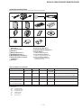 3
3
-
 4
4
-
 5
5
-
 6
6
-
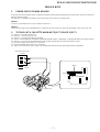 7
7
-
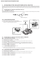 8
8
-
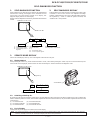 9
9
-
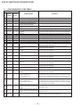 10
10
-
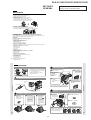 11
11
-
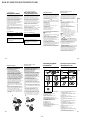 12
12
-
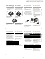 13
13
-
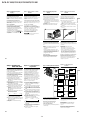 14
14
-
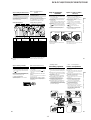 15
15
-
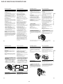 16
16
-
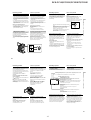 17
17
-
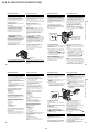 18
18
-
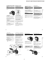 19
19
-
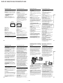 20
20
-
 21
21
-
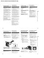 22
22
-
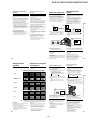 23
23
-
 24
24
-
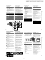 25
25
-
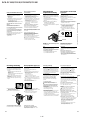 26
26
-
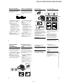 27
27
-
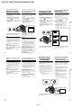 28
28
-
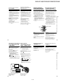 29
29
-
 30
30
-
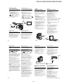 31
31
-
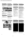 32
32
-
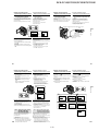 33
33
-
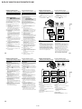 34
34
-
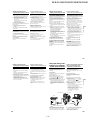 35
35
-
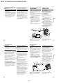 36
36
-
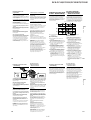 37
37
-
 38
38
-
 39
39
-
 40
40
-
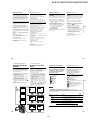 41
41
-
 42
42
-
 43
43
-
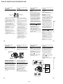 44
44
-
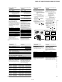 45
45
-
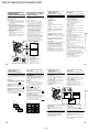 46
46
-
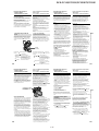 47
47
-
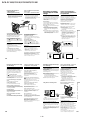 48
48
-
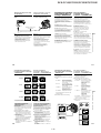 49
49
-
 50
50
-
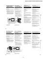 51
51
-
 52
52
-
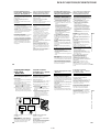 53
53
-
 54
54
-
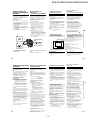 55
55
-
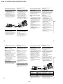 56
56
-
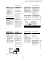 57
57
-
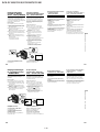 58
58
-
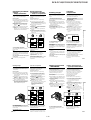 59
59
-
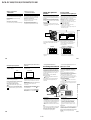 60
60
-
 61
61
-
 62
62
-
 63
63
-
 64
64
-
 65
65
-
 66
66
-
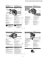 67
67
-
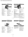 68
68
-
 69
69
-
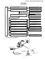 70
70
-
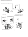 71
71
-
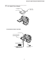 72
72
-
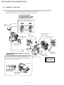 73
73
-
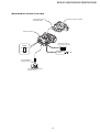 74
74
-
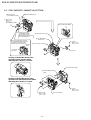 75
75
-
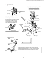 76
76
-
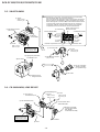 77
77
-
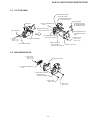 78
78
-
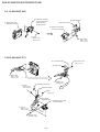 79
79
-
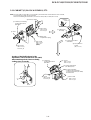 80
80
-
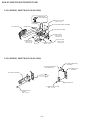 81
81
-
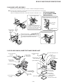 82
82
-
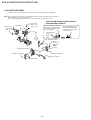 83
83
-
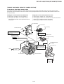 84
84
-
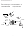 85
85
-
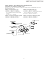 86
86
-
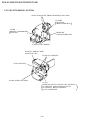 87
87
-
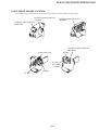 88
88
-
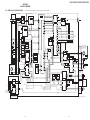 89
89
-
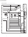 90
90
-
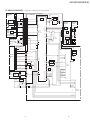 91
91
-
 92
92
-
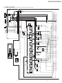 93
93
-
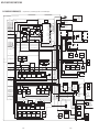 94
94
-
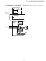 95
95
-
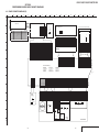 96
96
-
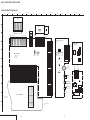 97
97
-
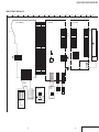 98
98
-
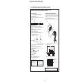 99
99
-
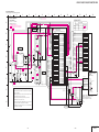 100
100
-
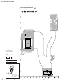 101
101
-
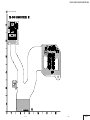 102
102
-
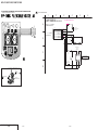 103
103
-
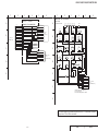 104
104
-
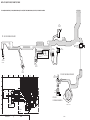 105
105
-
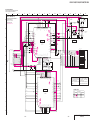 106
106
-
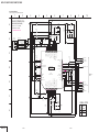 107
107
-
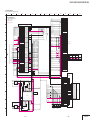 108
108
-
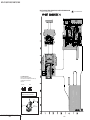 109
109
-
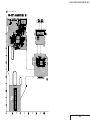 110
110
-
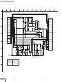 111
111
-
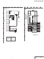 112
112
-
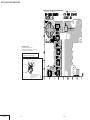 113
113
-
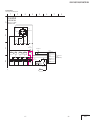 114
114
-
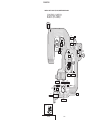 115
115
-
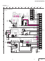 116
116
-
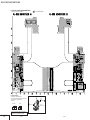 117
117
-
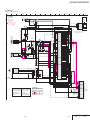 118
118
-
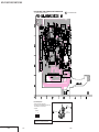 119
119
-
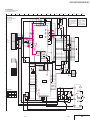 120
120
-
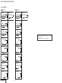 121
121
-
 122
122
-
 123
123
-
 124
124
-
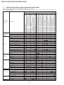 125
125
-
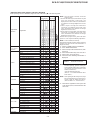 126
126
-
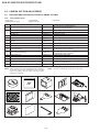 127
127
-
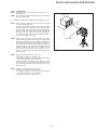 128
128
-
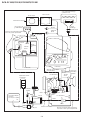 129
129
-
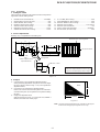 130
130
-
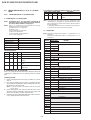 131
131
-
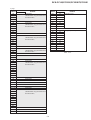 132
132
-
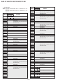 133
133
-
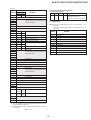 134
134
-
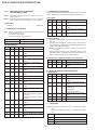 135
135
-
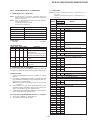 136
136
-
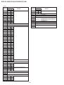 137
137
-
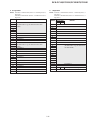 138
138
-
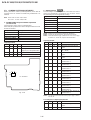 139
139
-
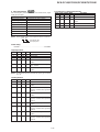 140
140
-
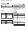 141
141
-
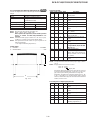 142
142
-
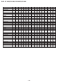 143
143
-
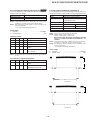 144
144
-
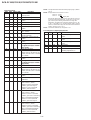 145
145
-
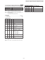 146
146
-
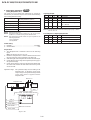 147
147
-
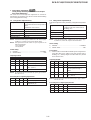 148
148
-
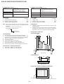 149
149
-
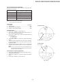 150
150
-
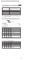 151
151
-
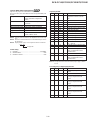 152
152
-
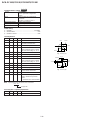 153
153
-
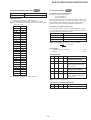 154
154
-
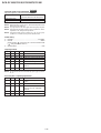 155
155
-
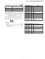 156
156
-
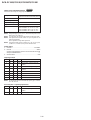 157
157
-
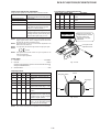 158
158
-
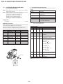 159
159
-
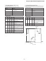 160
160
-
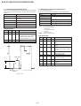 161
161
-
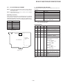 162
162
-
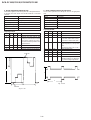 163
163
-
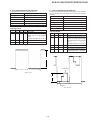 164
164
-
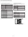 165
165
-
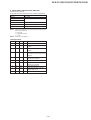 166
166
-
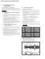 167
167
-
 168
168
-
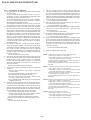 169
169
-
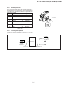 170
170
-
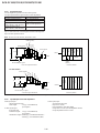 171
171
-
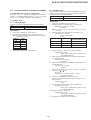 172
172
-
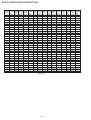 173
173
-
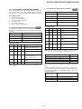 174
174
-
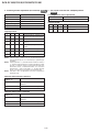 175
175
-
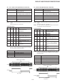 176
176
-
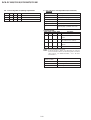 177
177
-
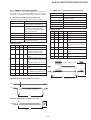 178
178
-
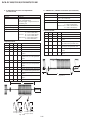 179
179
-
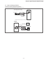 180
180
-
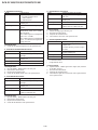 181
181
-
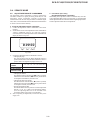 182
182
-
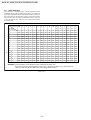 183
183
-
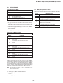 184
184
-
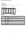 185
185
-
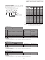 186
186
-
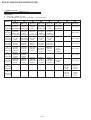 187
187
-
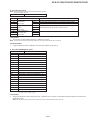 188
188
-
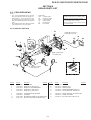 189
189
-
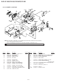 190
190
-
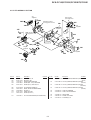 191
191
-
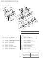 192
192
-
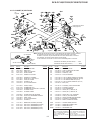 193
193
-
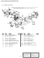 194
194
-
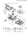 195
195
-
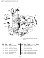 196
196
-
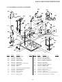 197
197
-
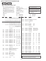 198
198
-
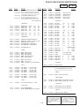 199
199
-
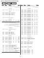 200
200
-
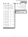 201
201
-
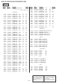 202
202
-
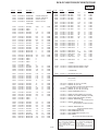 203
203
-
 204
204
-
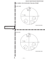 205
205
-
 206
206
-
 207
207


Sony DCR-PC115 Руководство пользователя
- Категория
- Видеокамеры
- Тип
- Руководство пользователя
Задайте вопрос, и я найду ответ в документе
Поиск информации в документе стал проще с помощью ИИ
на других языках
- English: Sony DCR-PC115 User manual
Похожие модели бренда
Модели других брендов
-
RIDGID micro CA-100 Руководство пользователя
-
ADA INSTRUMENTS ProDigit RUMB Инструкция по эксплуатации
-
Fagor VTR-16 Инструкция по применению
-
JVC KS-FX725R Руководство пользователя
-
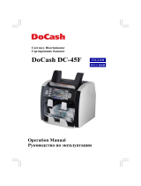 DoCash DC-45F Инструкция по эксплуатации
-
Ruck CPC 250 2EC 01 Инструкция по применению
-
Zebra G105910-139 Техническая спецификация
