Indesit MVK5 G1(W) RF Руководство пользователя
- Категория
- Аксессуары для кухни и посуды
- Тип
- Руководство пользователя
Это руководство также подходит для

Contents
Installation, 2-5
Positioning and levelling
Electrical connections
Gas connection
Adapting to different types of gas
Technical data
Table of burner and nozzle specifications
Description of the appliance, 6
Overall view
Control panel
Start-up and use, 7-9
Using the hob
Using the oven
Oven cooking advice table
Precautions and tips, 10
General safety
Disposal
Respecting and conserving the environment
Maintenance and care, 11
Switching the appliance off
Cleaning the appliance
Gas tap maintenance
Replacing the oven light bulb
Assistance
Operating Instructions
COOKER
GB
English, 1
РУССКИЙ, 12
RS
GB
MVK5 G1 RF
MVK5 G11 RF
MVK5 G1 RF
MVK5 G11 RF
MVK5 G1 RF
MVK5 G11 RF
MVK5 G17 RF
ҚазақшаҚазақша
KZ
MVK5 G17 RF
,25

2
GB
! Before operating your new appliance please read
this instruction booklet carefully. It contains
important information concerning the safe installation
and operation of the appliance.
! Please keep these operating instructions for future
reference. Make sure that the instructions are kept
with the appliance if it is sold, given away or moved.
! The appliance must be installed by a qualified
professional according to the instructions provided.
! Any necessary adjustment or maintenance must be
performed after the cooker has been disconnected
from the electricity supply.
! We recommend cleaning the oven before using it
for the first time, following the instructions provided
in the "Care and maintenance" section.
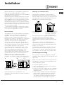
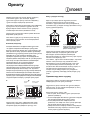
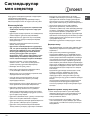
Room ventilation
The appliance may only be installed in permanently-
ventilated rooms, according to current national
legislation. The room in which the appliance is
installed must be ventilated adequately so as to
provide as much air as is needed by the normal gas
combustion process (the flow of air must not be
lower than 2 m
3
/h per kW of installed power).
The air inlets, protected by grilles, should have a
duct with an inner cross section of at least 100 cm
2
and should be positioned so that they are not liable
to even partial obstruction (
see figure A
).
These inlets should be enlarged by 100% - with a
minimum of 200 cm
2
- whenever the surface of the
hob is not equipped with a flame failure safety
device. When the flow of air is provided in an
indirect manner from adjacent rooms (
see figure B
),
provided that these are not communal parts of a
building, areas with increased fire hazards or
bedrooms, the inlets should be fitted with a
ventilation duct leading outside as described above.
AB
! After prolonged use of the appliance, it is
advisable to open a window or increase the speed of
any fans used.
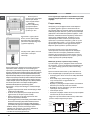
Disposing of combustion fumes
The disposal of combustion fumes should be
guaranteed using a hood connected to a safe and
efficient natural suction chimney, or using an electric
fan that begins to operate automatically every time
the appliance is switched on (
see figure
).
! The liquefied petroleum gases are heavier than air
and collect by the floor, therefore all rooms
containing LPG cylinders must have openings
leading outside so that any leaked gas can escape
easily.
LPG cylinders, therefore, whether partially or
completely full, must not be installed or stored in
rooms or storage areas that are below ground level
(cellars, etc.). Only the
cylinder being used should be stored in the room;
this should also be kept well away from sources
of heat (ovens, chimneys, stoves) that may cause
the temperature of the cylinder to rise above 50°C.
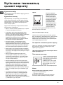
Positioning and levelling
! It is possible to install the appliance alongside
cupboards whose height does not exceed that of the
hob surface.
! Make sure that the wall in contact with the back of
the appliance is made from a non-flammable, heat-
resistant material (T 90°C).
To install the appliance correctly:
• Place it in the kitchen, dining room or the bed-sit
(not in the bathroom).
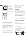
• If the top of the hob is higher than the cupboards,
the appliance must be installed at least 200 mm
away from them.
• If the cooker is installed underneath a wall cabinet,
there must be a minimum distance of 420 mm
between this cabinet and the top of the hob.
This distance should be increased to 700 mm if
the wall cabinets are flammable (
see figure
).
A
Fumes channelled through
a chimney or branched
flue system reserved for
cooking appliances)
Installation
Adjacent room Room requiring
ventilation
Ventilation opening for
comburent air
Increase in the gap between
the door and the flooring
Fumes channelled
straight outside

3
GB
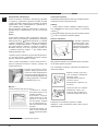
• Do not position
blinds behind the
cooker or less than 200
mm away from its
sides.
• Any hoods must be
installed according to
the instructions listed in
the relevant operating
manual.
Levelling
If it is necessary to level the
appliance, screw the
adjustable feet into the places
provided on each corner of the
base of the cooker (
see
figure
).
The legs* fit into the slots on
the underside of the base of
the cooker.
Electrical connection
Install a standardised plug corresponding to the
load indicated on the appliance data plate (
see
Technical data table
).
The appliance must be directly connected to the mains
using an omnipolar circuit-breaker with a minimum
contact opening of 3 mm installed between the
appliance and the mains. The circuit-breaker must be
suitable for the charge indicated and must comply with
NFC 15-100 regulations (the earthing wire must not be
interrupted by the circuit-breaker). The supply cable
must be positioned so that it does not come into
contact with temperatures higher than 50°C at any point.
Before connecting the appliance to the power
supply, make sure that:
• The appliance is earthed and the plug is compliant
with the law.
• The socket can withstand the maximum power of
the appliance, which is indicated by the data plate.
• The voltage is in the range between the values
indicated on the data plate.
• The socket is compatible with the plug of the
appliance. If the socket is incompatible with the
plug, ask an authorised technician to replace it.
Do not use extension cords or multiple sockets.
HOOD
420
Min.
min.
650
mm. with hood
min.
700
mm. without hood
mm.
600
Min. mm.
420
Min. mm.
* Only available in certain models
! Once the appliance has been installed, the power
supply cable and the electrical socket must be
easily accessible.
! The cable must not be bent or compressed.
! The cable must be checked regularly and replaced
by authorised technicians only.
! The manufacturer declines any liability should
these safety measures not be observed.
Gas connection
Connection to the gas network or to the gas cylinder
may be carried out using a flexible rubber or steel
hose, in accordance with current national legislation
and after making sure that the appliance is suited to
the type of gas with which it will be supplied (see the
rating sticker on the cover: if this is not the case
see
below
). When using liquid gas from a cylinder, install a
pressure regulator which complies with current national
regulations. To make connection easier, the gas
supply may be turned sideways*: reverse the position
of the hose holder with that of the cap and replace the
gasket that is supplied with the appliance.
! Check that the pressure of the gas supply is
consistent with the values indicated in the Table of
burner and nozzle specifications (
see below
). This
will ensure the safe operation and durability of your
appliance while maintaining efficient energy
consumption.
Gas connection using a flexible rubber hose
Make sure that the hose complies with current
national legislation. The internal diameter of the hose
must measure: 8 mm for liquid gas supply; 13 mm
for methane gas supply.
Once the connection has been performed, make
sure that the hose:
• Does not come into contact with any parts that
reach temperatures of over 50°C.
• Is not subject to any pulling or twisting forces and
that it is not kinked or bent.
• Does not come into contact with blades, sharp
corners or moving parts and that it is not
compressed.
• Is easy to inspect along its whole length so that
its condition may be checked.
• Is shorter than 1500 mm.
• Fits firmly into place at both ends, where it will be
fixed using clamps that comply with current
regulations.

4
GB
A
V
! If one or more of these conditions is not fulfilled or
if the cooker must be installed according to the
conditions listed for class 2 - subclass 1 appliances
(installed between two cupboards), the flexible steel
hose must be used instead (
see below
).
Connecting a flexible jointless stainless steel pipe
to a threaded attachment
Make sure that the hose and gaskets comply with
current national legislation.
To begin using the hose, remove the hose holder on the
appliance (the gas supply inlet on the appliance is a
cylindrical threaded 1/2 gas male attachment).
! Perform the connection in such a way that the hose
length does not exceed a maximum of 2 metres,
making sure that the hose is not compressed and
does not come into contact with moving parts.
Checking the connection for leaks
When the installation process is complete, check
the hose fittings for leaks using a soapy solution.
Never use a flame.
Adapting to different types of gas
It is possible to adapt the appliance to a type of gas
other than the default type (this is indicated on the
rating label on the cover).
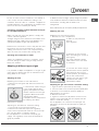
Adapting the hob
Replacing the nozzles for the hob burners:
1. Remove the hob grids and slide the burners off
their seats.
2. Unscrew the nozzles using a
7 mm socket spanner (
see
figure
), and replace them with
nozzles suited to the new type
of gas(
see Burner and nozzle
specifications table
).
3. Replace all the components
by following the above
instructions in reverse.
Adjusting the hob burners’ minimum setting:
1. Turn the tap to the minimum position.
2. Remove the knob and adjust the regulatory
screw, which is positioned inside or next to the tap
pin, until the flame is small but steady.
! If the appliance is connected to a liquid gas
supply, the regulatory screw must be fastened as
tightly as possible.
3. While the burner is alight, quickly change the position
of the knob from minimum to maximum and vice versa
several times, checking that the flame is not
extinguished.
! The hob burners do not require primary air adjustment.
Adapting the oven
Replacing the oven burner nozzle:
1. Remove the oven compartment.
2. Slide out the protection
panel A
(
see diagram
).
3. Remove the oven burner
after unscrewing the screws V
(
see figure
).
The whole operation will be
made easier if the oven door
is removed.
4. Unscrew the nozzle using a
special nozzle socket spanner
(
see figure
) or with a 7 mm
socket spanner, and replace it
with a new nozzle that is
suited to the new type of gas
(
see Burner and nozzle
specifications table
).
Adjusting the gas oven burner’s minimum setting:
1. Light the burner (
see Start-up and Use
).
2. Turn the knob to the minimum position (MIN) after
it has been in the maximum position (MAX) for
approximately 10 minutes.
3. Remove the knob.
4. Tighten or loosen the adjustment screws on the
outside of the thermostat pin (
see figure
) until the
flame is small but steady.
! If the appliance is connected to liquid gas, the
adjustment screw must be fastened as tightly as
possible.

5
GB
5. Turn the knob from the MAX position to the MIN
position quickly or open and shut the oven door,
making sure that the burner is not extinguished.
Adapting the grill*
Replacing the grill burner nozzle:
1. Remove the oven burner
after loosening screw V (
see
figure
).
2. Unscrew the grill burner
nozzle using a special nozzle
socket spanner (
see figure
) or
preferably with a 7 mm socket
spanner, and replace it with a
new nozzle that is suited to the
new type of gas (
see Burner
and nozzle specifications table
).
! Be careful of the spark plug wires and the
thermocouple tubes.
! The oven and grill burners do not require primary
air adjustment.
! After adjusting the appliance so it may be used
with a different type of gas, replace the old rating
label with a new one that corresponds to the new
type of gas (these labels are available from
Authorised Technical Assistance Centres).
! Should the gas pressure used be different (or vary
slightly) from the recommended pressure, a suitable
pressure regulator must be fitted to the inlet hose in
accordance with current national regulations relating
to “regulators for channelled gas”.
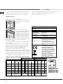
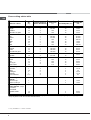
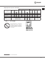
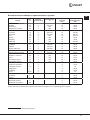
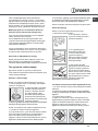
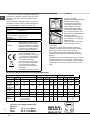
Table of burner and nozzle specifications
V
I
S
S
R
A
TECHNICAL DATA
Oven dimensions
(HxWxD)
34x39x44 cm
Volume
58 l
Useful
measurements
relating to the oven
compartment
width 42 cm
depth 44 cm
height 17 cm
Power supply voltage
and frequency
see data plate
Burners
may be adapted for use with any
type of gas shown on the data
plate, which is located inside the
flap or, after the oven
compartment has been opened,
on the left-hand wall inside the
oven.
EC Directives: 2006/95/EC dated
12/12/06 (Low Voltage) and
subsequent amendments -
2004/108/EC dated 15/12/04
(Electromagnetic Compatibility)
and subsequent amendments -
2009/142/EC dated 30/11/09
(Gas) and subsequent
amendments - 93/68/EEC dated
22/07/93 and subsequent
amendments - 2002/96/EC.
1275/2008 (Stand-by/ Off mode)
Table 1 Liquid Gas Natural Gas
Burner Diameter
(mm)
Thermal Power
kW (p.c.s.*)
By-Pass
1/100
Nozzle
1/100
Flow*
g/h
Nozzle
1/100
Flow*
l/h
Nozzle
1/100
Flow*
l/h
Nominal Reduced (mm) (mm) *** ** (mm) (mm)
Fast
(Large)(R)
100 3.00 0.7 41 87 218 214 128 286 143 286
Semi Fast
(Medium)(S)
75 1.90 0.4 30 70 138 136 104 181 118 181
Auxiliary
(Small)(A)
51 1.00 0.4 30 52 73 71 76 95 80 95
Oven - 2.80 1.0 46 80 204 200 119 267 132 257
139 227
Supply
Pressures
Nominal (mbar)
Minimum (mbar)
Maximum (mbar)
28-30
20
35
37
25
45
20
17
25
13
6,5
18
We recommend cleaning the oven before using it for the
first time, following the instructions provided in the
"Care and maintenance" section.
Grill - 2.30 - - 75 167 164 114 219
MVK5 G1 RF
MVK5 G11 RF
MVK5 G1 RF
MVK5 G11 RF
MVK5 G1 RF
MVK5 G11 RF
*
Only available in certain models.
MVK5 G17 RFMVK5 G17 RF

6
GB
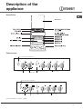
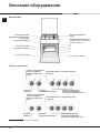
Description of the
appliance
*
Only available in certain models.
Control panel
Overall view
Electronic Lighting for Hob Burners *
Control Knobs for Gas
Burners on Hob
Oven and Grill*
Control Knob
Button for Oven
Light and Rotisserie *
Timer Knob*
Electronic Lighting for Hob Burners *
Control Knobs for Gas
Burners on Hob
Oven and Grill*
Control Knob
Button for Oven
Light and Rotisserie *
Timer Knob*
The cover*

7
GB
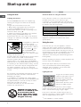
Using the hob
Lighting the burners
For each BURNER knob there is a complete ring
showing the strength of the flame for the relevant
burner.
To light one of the burners on the hob:
1. Bring a flame or gas lighter close to the burner.
2. Press the BURNER knob and turn it in an
anticlockwise direction so that it is pointing to the
maximum flame setting E.
3. Adjust the intensity of the flame to the desired
level by turning the BURNER knob in an
anticlockwise direction. This may be the minimum
setting C, the maximum setting E or any position
in between the two.
If the appliance is fitted with
an electronic lighting
device* (
see figure
), press
the ignition button, marked
with the symbol , then
hold the BURNER knob
down and turn it in an
anticlockwise direction, towards the maximum flame
setting, until the burner is lit.
Several models are equipped with an ignition device
which is built into the knob; in this case the
electronic ignition device* is present (
C
) but the
ignition button is not. Simply press the BURNER
knob and turn it in an anticlockwise direction so that
it is pointing to the maximum flame setting, until the
burner is lit. The burner may be extinguished when
the knob is released. If this occurs, repeat the
operation, holding the knob down for a longer period
of time.
! If the flame is accidentally extinguished, switch off
the burner and wait for at least 1 minute before
attempting to relight it.
If the appliance is equipped with a flame failure
safety device*(X), press and hold the BURNER knob
for approximately 2-3 seconds to keep the flame
alight and to activate the device.
To switch the burner off, turn the knob until it
reaches the stop position •.
Start-up and use
Practical advice on using the burners
For the burners to work in the most efficient way
possible and to save on the amount of gas
consumed, it is recommended that only pans that
have a lid and a flat base are used. They should also
be suited to the size of the burner.
To identify the type of burner, please refer to the
diagrams contained in the “Burner and nozzle
specifications”.
Using the oven
! The first time you use your appliance, heat the
empty oven with its door closed at its maximum
temperature for at least half an hour. Ensure that the
room is well ventilated before switching the oven off
and opening the oven door. The appliance may emit a
slightly unpleasant odour caused by protective
substances used during the manufacturing process
burning away.
! Before operating the product, remove all plastic film
from the sides of the appliance.
! Never put objects directly on the bottom of the
oven; this will avoid the enamel coating being
damaged. Only use position 1 in the oven when
cooking with the rotisserie spit.
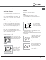
Lighting the oven
To light the oven burner, bring
a flame or gas lighter close to
opening F (
see figure
) and
press the OVEN control knob
while turning it in an
anticlockwise direction until it
reaches the MAX position.
If, after 15 seconds, the burner is still not alight,
release the knob, open the oven door and wait for at
least 1 minute before trying to light it again.
! The oven is fitted with a safety device and it is
therefore necessary to hold the OVEN control knob
down for approximately 6 seconds.
F
*
Only available in certain models.
Burner ø Cookware diameter (cm)
Fast (R) 24 - 26
Semi Fast (S) 16 - 20
Auxiliary (A) 10 - 14
X
C
WARNING! The glass lid canWARNING! The glass lid can
WARNING! The glass lid canWARNING! The glass lid can
WARNING! The glass lid can
break in if it is heated up. Turnbreak in if it is heated up. Turn
break in if it is heated up. Turnbreak in if it is heated up. Turn
break in if it is heated up. Turn
off all the burners and theoff all the burners and the
off all the burners and theoff all the burners and the
off all the burners and the
electric plates before closingelectric plates before closing
electric plates before closingelectric plates before closing
electric plates before closing
the lid. *Applies to the modelsthe lid. *Applies to the models
the lid. *Applies to the modelsthe lid. *Applies to the models
the lid. *Applies to the models
with glass cover only.with glass cover only.
with glass cover only.with glass cover only.
with glass cover only.

8
GB
* Only available in certain models.
! If the flame is accidentally extinguished, switch off
the burner and wait for at least 1 minute before
attempting to relight the oven.
Adjusting the temperature
To set the desired cooking temperature, turn the
OVEN control knob in an anticlockwise direction.
Temperatures are displayed on the control panel and
may vary between MIN (140°C) and MAX (250°C).
Once the set temperature has been reached, the
oven will keep it constant by using its thermostat.
Grill*
To light the grill, bring a flame or gas lighter close to
the burner and press the OVEN control knob while
turning it in a clockwise direction until it reaches the
d position. The grill enables the surface of food to
be browned evenly and is particularly suitable for
roast dishes, schnitzel and sausages. Place the
rack in position 4 or 5 and the dripping pan in
position 1 to collect fat and prevent the formation of
smoke.
! The grill is fitted with a safety device and it is
therefore necessary to hold the OVEN control knob
down for approximately 6 seconds.
! If the flame is accidentally extinguished, switch off
the burner and wait for at least 1 minute before
attempting to relight the grill.
! When using the grill, leave
the oven door ajar, positioning
the deflector D between the
door and the control panel
(
see figure
) in order to prevent
the knobs from overheating.
Turnspit*
To operate the
rotisserie (
see diagram
)
proceed as follows:
1. Place the dripping
pan in position 1.
2. Place the rotisserie
support in position 4
and insert the spit in the
hole provided on the
back panel of the oven.
3. Acitvate the function by pressing the TURNSPIT
button.
Oven light
The light may be switched on at any moment by
pressing the OVEN LIGHT button.
Timer*
To activate the Timer proceed as follows:
1. Turn the TIMER knob in a clockwise direction 4
for almost one complete revolution to set the buzzer.
2. Turn the TIMER knob in an anticlockwise direction
5 to set the desired length of time.
Lower compartment*
There is a compartment
underneath the oven
that may be used to
store oven accessories
or deep dishes. To open
the door pull it
downwards (
see figure
).
! The internal surfaces of the compartment (where
present) may become hot.
! Do not place flammable materials in the lower oven
compartment.
D
A
S
In gas cooker models, there is
a sliding protection layer A
that shields the lower
compartment from the heat
generated by the burner (
see
figure
).
To remove the sliding
protection remove the screw S
(
see figure
). To replace it, lock
it in place with the screw S.
! Before using the oven make
sure that the sliding protection
is fixed correctly.

9
GB
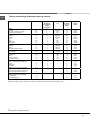
Oven cooking advice table
* Only available in certain models.
Food to be cooked
Wt.
(Kg)
Cooking position of
shelves from bottom
Temperature
(°C)
Pre-heating time (min)
Cooking time
(min.)
Pasta
Lasagne
Cannelloni
Pasta bakes au gratin
2.5
2.5
2.5
4
4
4
200-210
200
200
10
10
10
75-85
50-60
50-60
Meat
Ve al
Chicken
Duck
Rabbit
Pork
Lamb
1.5
1.5
1.8
2.0
2.1
1.8
3
3
3
3
3
3
200-210
210-220
200
200
200
200
10
10
10
10
10
10
95-100
90-100
100-110
70-80
70-80
100-105
Fish
Mackerel
Dentex
Trout baked in paper
1.1
1.5
1.0
3
3
3
180-200
180-200
180-200
10
10
10
45-50
45-55
45-50
Pizza
Napolitan 1.0 4 210-220 15
20-25
Cake
Biscuits
Ta rts
Savoury pie
Raised Cakes
0.5
1.1
1.0
1.0
4
4
4
4
180
180
180
170
15
15
15
15
25-35
40-45
50-55
40-45
Grill cooking
Veal steaks
Cutlets
Hamburgers
Mackerels
Toast sandwiches
1
1,5
1
1
n.° 4
4
4
4
3
4
4
5
5
5
5
5
15-20
20
20-30
15-20
4-5
Grill cooking with
rotisserie
Veal on the spit
Chicken on the spit
1
2
-
-
5
5
70-80
70-80
Grill cooking with multi-
skewer rotisserie (only a
few models)
Meat kebabs
Vegetable kebabs 1,0
0,8
-
-
5
5
40-45
25-30
NB: cooking times are approximate and may vary according to personal taste. When cooking using the grill, the dripping-pan must
always be placed on the 1st oven rack from the bottom.

10
GB
Precautions and tips
! This appliance has been designed and manufactured in
compliance with international safety standards.
The following warnings are provided for safety reasons and
must be read carefully.
General safety
• These instructions are only valid for the
countries whose symbols appear in the
manual and on the serial number plate.•
The appliance was designed for domestic use inside the
home and is not intended for commercial or industrial use.
• The appliance must not be installed outdoors, even in
covered areas. It is extremely dangerous to leave the
appliance exposed to rain and storms.
• Do not touch the appliance with bare feet or with wet or
damp hands and feet.
• The appliance must be used by adults only for
the preparation of food, in accordance with the
instructions outlined in this booklet. Any other
use of the appliance (e.g. for heating the room)
constitutes improper use and is dangerous.
The manufacturer may not be held liable for
any damage resulting from improper, incorrect
and unreasonable use of the appliance.
• The instruction booklet accompanies a class 1 (insulated)
or class 2 - subclass 1 (recessed between 2 cupboards)
appliance.
• Keep children away from the oven.
• Make sure that the power supply cables of other electrical
appliances do not come into contact with the hot parts of
the oven.
• The openings used for the ventilation and dispersion of
heat must never be covered.
• Do not close the glass hob cover (selected models only)
when the burners are alight or when they are still hot.
• Always use oven gloves when placing cookware in the
oven or when removing it.
• Do not use flammable liquids (alcohol, petrol, etc...) near
the appliance while it is in use.
• Do not place flammable material in the lower storage
compartment or in the oven itself. If the appliance is
switched on accidentally, it could catch fire.
• Always make sure the knobs are in the • position and that
the gas tap is closed when the appliance is not in use.
• When unplugging the appliance, always pull the plug from
the mains socket; do not pull on the cable.
• Never perform any cleaning or maintenance work without
having disconnected the appliance from the electricity
mains.
• If the appliance breaks down, under no circumstances
should you attempt to repair the appliance yourself.
Repairs carried out by inexperienced persons may cause
injury or further malfunctioning of the appliance. Contact
Assistance.
• Do not rest heavy objects on the open oven door.
• The appliance should not be operated by people
(including children) with reduced physical,
sensory or mental capacities, by inexperienced
individuals or by anyone who is not familiar with
the product. These individuals should, at the very
least, be supervised by someone who assumes
responsibility for their safety or receive
preliminary instructions relating to the operation of
the appliance.
• Do not let children play with the appliance.
Disposal
• When disposing of packaging material: observe local
legislation so that the packaging may be reused.
• The European Directive 2002/96/EC relating to Waste
Electrical and Electronic Equipment (WEEE) states that
household appliances should not be disposed of using the
normal solid urban waste cycle. Exhausted appliances
should be collected separately in order to optimise the cost
of re-using and recycling the materials inside the machine,
while preventing potential damage to the atmosphere and
to public health. The crossed-out dustbin is marked on all
products to remind the owner of their obligations regarding
separated waste collection.
Exhausted appliances may be collected by the public
waste collection service, taken to suitable collection areas
in the area or, if permitted by current national legislation,
they may be returned to the dealers as part of an
exchange deal for a new equivalent product.
All major manufacturers of household appliances
participate in the creation and organisation of systems for
the collection and disposal of old and disused appliances.
Respecting and conserving the
environment
• Check the door seals regularly and wipe them clean to
ensure they are free of debris so that they adhere properly
to the door, thus avoiding
heat dispersion.

11
GB
Care and maintenance
Switching the appliance off
Disconnect your appliance from the electricity supply
before carrying out any work on it.
Cleaning the appliance
! Do not use abrasive or corrosive detergents such as
stain removers, anti-rust products, powder detergents or
sponges with abrasive surfaces: these may scratch the
surface beyond repair.
! Never use steam cleaners or pressure cleaners on the
appliance.
• It is usually sufficient simply to wash the hob using a
damp sponge and dry it with absorbent kitchen roll.
• The stainless steel or enamel-coated external parts and
the rubber seals may be cleaned using a sponge that
has been soaked in lukewarm water and neutral soap.
Use specialised products for the removal of stubborn
stains. After cleaning, rinse well and dry thoroughly. Do
not use abrasive powders or corrosive substances.
• The hob grids, burner caps, flame spreader rings
and the hob burners can be removed
to make cleaning easier; wash them in hot water and
non-abrasive detergent, making sure all burnt-on
residue is removed before drying them thoroughly.
• For hobs with electronic ignition, the terminal part of the
electronic lighting devices should be cleaned
frequently and the gas outlet holes should be checked
for blockages.
• The inside of the oven should ideally be cleaned after
each use, while it is still lukewarm. Use hot water and
detergent, then rinse well and dry with a soft cloth. Do
not use abrasive products.
•
Clean the glass part of the oven door using a sponge
and a non-abrasive cleaning product, then dry
thoroughly with a soft cloth. Do not use rough abrasive
material or sharp metal scrapers as these could
scratch the surface and cause the glass to crack.
• The accessories can be washed like everyday
crockery, and are even dishwasher safe.
• Stainless steel can be marked by hard water that has
been left on the surface for a long time, or by
aggressive detergents containing phosphorus. After
cleaning, rinse well and dry thoroughly. Any remaining
drops of water should also be dried.
The cover
If the cooker is fitted with a
glass cover, this cover
should be cleaned using
lukewarm water. Do not use
abrasive products.
It is possible to remove the
cover in order to make
cleaning the area behind
the hob easier. Open the
cover fully and pull it
upwards (
see figure
).
! Do not close the cover when the burners are alight or
when they are still hot.
Inspecting the oven seals
Check the door seals around the oven periodically. If the
seals are damaged, please contact your nearest
Authorised After-sales Service Centre. We recommend
that the oven is not used until the seals have been
replaced.
Gas tap maintenance
Over time, the taps may become jammed or difficult to
turn. If this occurs, the tap must be replaced.
!
This procedure must be performed by a qualifiedThis procedure must be performed by a qualified
This procedure must be performed by a qualifiedThis procedure must be performed by a qualified
This procedure must be performed by a qualified
technician who has been authorised by thetechnician who has been authorised by the
technician who has been authorised by thetechnician who has been authorised by the
technician who has been authorised by the
manufacturer.manufacturer.
manufacturer.manufacturer.
manufacturer.
Replacing the oven light bulb
1. After disconnecting the oven
from the electricity mains, remove
the glass lid covering the lamp
socket (
see figure
).
2. Remove the light bulb and
replace it with a similar one:
voltage 230 V, wattage 25 W, cap
E 14.
3. Replace the lid and reconnect the oven to the electricity
supply.
Assistance
Please have the following information handy:
• The appliance model (Mod.).
• The serial number (S/N).
This information can be found on the data plate located on
the appliance and/or on the packaging.

Руководство по эксплуатации
КОМБИНИРОВАННАЯ (ГАЗОВАЯ) ПЛИТА
RS
Русский
Содержание
Информация для потребителя, 13
Установка, 14-18
Размещение и выравнивание
Подключение к электросети
Подключение к газу
Настройка на различные типы газа
Технические характеристики
Характеристики горелок и жиклеров
Описание оборудования, 19
Внешний вид
Панель управления
Включение и использование, 20-22
Использование рабочей поверхности
Использование духовки
Вспомогательная таблица по приготовлению
в духовке
Предупреждения и рекомендации, 23
Основные правила безопасности
Утилизация
Экономия электроэнергии и охрана окружающей
среды
Обслуживание и уход, 24
Отключение оборудования
Чистка оборудования
Уход за вентилями рукояток
Замена лампы освещения
Помощь
English, 1
, 12
GB
MVK5 G1 RF
MVK5 G11 RF
MVK5 G1 RF
MVK5 G11 RF
MVK5 G1 RF
MVK5 G11 RF
MVK5 G17 RFMVK5 G17 RF
ҚазақшаҚазақша
KZ
,25

13
RS
Изделие: Комбинированная (газовая) плита
Торговая марка:
Торговый знак изготовителя:
Модели:
Изготовитель: Indesit Company
Страна-изготовитель: Польша
Номинальное значение напряжения электропитания
или диапазон напряжения
220–240 В ~
Условное обозначение рода электрического тока
или номинальная частота переменного тока
50/60 Гц
Класс защиты от поражения электрическим током Класс защиты I
Объем духового шкафа 58 л
Макс. поглощаемая мощность (газовая духовка) 3100 Вт
В случае необходимости получения информации
по сертификатам соответствия
или получения копий
сертификатов соответствия на данную технику, Вы
можете отправить запрос по электронному адресу
Дату производства данной техники можно
получить из серийного номера, расположенного
под штрих-кодом
(S/N XXXXXXXXX * XXXXXXXXXXX),
следующим образом:
- 1-я цифра в S/N соответствует последней цифре
года;
- 2-я и 3-я цифры в S/N — порядковому номеру
месяца года,
- 4-я и 5-я цифры в S/N — числу определенного
месяца и года.
Производитель оставляет за собой право без предупреждения вносить
изменения в конструкцию и комп-
лектацию, не ухудшающие эффективность работы оборудования. Некоторые параметры, приведенные
в этой инструкции, являются приблизительными. Производитель не несет ответственности за незначитель-
ные отклонения от указанных величин. Изготовитель не несет ответственности за возможные неточности
в этой брошюре из-за печати или копирования ошибок.
Производитель: Indesit Company S.p.A.
Виале А. Мерлони 47, 60044, Фабриано (АН), Италия
Импортер: ООО «Индезит РУС»
С вопросами (в России) обращаться по адресу: Россия, 127018, Москва, ул. Двинцев, дом 12, корп. 1
Информация для потребителя
MVK5 G1 RF
MVK5 G11 RF
MVK5 G17 RF

14
RS
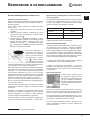
Установка
! Перед установкой и подключением вашего нового
оборудования внимательно прочитайте данное ру-
ководство: в нем содержатся важные сведения по
установке, безопасной эксплуатации и обслуживанию
оборудования.
! Сохраните руководство как источник справочной
информации по оборудованию и для передачи воз-
можным новым владельцам.
! Установка оборудования должна производиться
квалифицированным персоналом в соответствии
с приводимыми
инструкциями.
! Перед регулировкой или обслуживанием оборудо-
вания его следует отключить от электросети.
Вентиляция помещения
В соответствии с действующими стандартами по
установке газового оборудования плита может быть
установлена только в помещениях с постоянной вен-
тиляцией. Помещение должно иметь вентиляционную
систему, обеспечивающую удаление продуктов сго-
рания (приток воздуха должен составлять не менее
2
м
3
/ч на каждый киловатт мощ ности устанавлива-
емого оборудования). Труба, идущая к входному
вентиляционному отверстию, защищенному решет-
кой, должна иметь внутреннее поперечное сечение
100 см
2
и проложена так, чтобы исключить засорение
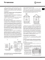
в любой ее части (рис. A).
Если рабочая поверхность плиты не оснащена ус-
тройством безопасности, входное вентиляционное
отверстие должно быть увеличено на 100% (с мини-
мальным поперечным сечением трубы 200 см
2
).
Когда поток воздуха поступает из смежных помещений
(при условии, что они не являются коммунальными
частями здания, пожароопасными помещениями или
спальнями), их входные вентиляционные отверстия
также должны быть оснащены наружной воздухоот-
водной трубой, как описано выше (рис. B).
Отвод отработанного воздуха
Эффективное удаление продуктов сгорания будет
обеспечено при использовании вытяжки, подключен-
ной
к наружному дымоотводу, или электрического
вентилятора, автоматически включающегося каждый
раз, когда оборудование работает (cм. рис.).
Пример обеспечения
притока воздуха
Смежное
помещение
Помещение,
требую щее
вентиляции
Увеличение зазора
между дверью и полом
для свободного прохода
приточного воздуха
AB
! После продолжительного использования оборудова-
ния желательно открыть окно или увеличить скорость
работающего вентилятора.
Прямая вытяжка наружу
Вытяжка при наличии
дымохода (только
для кухонного оборудования)
!
Сжиженный газ тяжелее воздуха, и поэтому скапли-
вается внизу. Помещения, в которых устанавливаются
баллоны со сжиженным газом, должны быть осна-
щены наружной вентиляцией, чтобы через нее мог
уходить газ в случае утечки. Нельзя устанавливать и
хранить баллоны с газом в помещениях, расположен-
ных ниже уровня пола (в подвалах и полуподвалах).
Рекомендуем держать в кухне только используемый
баллон и устанавливать его подальше от источников
тепла (духовок, каминов, печей и т.п.), способных
нагреть баллон до температуры выше 50°С.
Размещение и выравнивание
!
Плита может быть установлена рядом с любой
кухонной мебелью, не превышающей оборудование
по высоте.
!
Стена, соприкасающаяся с задней частью оборудо-
вания, должна быть сделана из невоспламеняющих-
ся, термостойких материалов (выдерживать нагрев
до 90 °C).
Для правильной установки:
Разместите оборудование в кухне, столовой, но не
в ванной комнате.
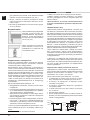
Если рабочая поверхность плиты выше рядом
стоящей кухонной мебели, последняя должна нахо-
диться на расстоянии
не менее 200 мм от
оборудования.
Минимальное расстоя-
ние между рабочей
поверх ностью плиты
и навесными шкафа-
ми (полками) должно
составлять 420 мм.
Это расстояние сле-
•
•
•

15
RS
дует увеличить до 700 мм, если навесные шкафы
сделаны из горючих ма те риалов (см. рис.).
Шторы / жалюзи не должны находиться позади
плиты или на расстоянии менее 200 мм от ее бо-
ковых сторон.
Вытяжки устанавливаются согласно их инструкци-
ям по установке.
Выравнивание
Плита снабжена регулируемыми
ножками, которые служат для
ее выравнивания. При необхо-
димости, ножки вкручи ваются
в отверстия по углам основания
плиты (см. рис.).
Плита комплектуется надстав-
ными опорами*, которые уста-
навливаются в отверстия под
основанием плиты.
Подключение к электросети
Оснастите питающий кабель стандартной вилкой,
соответствующей нагрузке, указанной в табличке
технических данных оборудования.
Оборудование может напрямую подсоединяться
к сети с использованием многолинейного автомати-
ческого выключателя (соответствующего техническим
нормам и нагрузке оборудования), расстоя ние между
разведенными контактами которого не менее 3 мм,
линия заземления не должна прерываться выключа-
телем. Питающий кабель следует расположить так,
чтобы по всей длине он никогда не нагревался до
температуры, превышающей на 50 °С температуру
в помещении.
Перед подсоединением проверьте, что:
• Оборудование заземлено и вилка соответствует
стандартам.
• Розетка может выдержать максимальную нагрузку
от устанавливаемого оборудования (см. табличку
технических данных оборудования).
• Электрическое напряжение соответствует диапа-
зону значений, указанных в
табличке технических
данных оборудования.
• Розетка подходит к вилке оборудования, в против-
ном случае — обратитесь к квалифицированному
специалисту для замены розетки. Не используйте
удлинители и многогнездовые розетки.
* Только для некоторых модификаций моделей.
•
•
! После установки оборудования должен быть обес-
печен свободный доступ к питающему кабелю и ро-
зетке.
! Кабель не должен быть перекручен или пережат.
! Кабель следует регулярно проверять, его замена
должна производиться только специалистами сер-
висного центра.
Производитель не несет ответственности
в случае несоблюдения указанных мер безопас-
ности.
Подключение к газу
Подключение данного оборудования к газовой сети
или баллону с газом может быть выполнено при помо-
щи гибкого резинового или стального шланга, согласно
действующим нормам подключения и после проверки
соответствия типа подключаемого газа тому, на который
настроено оборудование (см. маркировку на корпусе
оборудования): в ином случае следуйте инструкциям
§ «Настройка на различные
типы газа». Если плита
подсоединяется к баллону со сжиженным газом, на
баллон с газом необходимо установить регулятор
давления (редуктор), отвечающий действующим стан-
дартом подключения газового оборудования.
Чтобы облегчить подключение, подвод газа может
быть осуществлен с обеих сторон оборудования*:
поменяйте положение держателя шланга и за глушки
и замените уплотнительную прокладку (поставляется
с оборудованием).
! Убедитесь, что давление газа соответствует значе-
ниям, указанным в таблице «Характеристики горелок
и жиклеров». Это обеспечит безопасную работу и дол-
гий срок службы оборудования при эффективном
энергопотреблении.
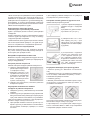
Подключение гибким резиновым шлангом
Подсоедините газовый шланг, характеристики кото-
рого отвечают действующим стандартам. Внутренний
диаметр шланга должен составлять: 8 мм — для
сжиженного газа
; 13 мм— для метана
После подключения удостоверьтесь, что шланг:
по всей длине не касается частей плиты, которые
могут нагреваться до температуры выше 50 °С;
не натянут, не перекручен, не образует петель
и изгибов, не пережат;
не касается подвижных объектов и предметов
с острыми углами;
по всей длине доступен для осмотра и контроля
его состояния;
длиной менее 1500 мм;
прочно зафиксирован на месте с обоих концов за-
жимами, соответствующими нормам подключения
газового оборудования.
•
•
•
•
•
•
Крепление
шланга
Точка соединения
Точка соединения
Изолирующая
заглушка
Изолирующая
заглушка
Крепление
шланга
ГОРЯЧАЯ ПОВЕРХНОСТЬ

16
RS
! Если хотя бы одно из приведенных выше требований
не удается выполнить, или, если плита должна уста-
навливаться по правилам, относящимся к бытовым
приборам класса 2 подкласса 1 (установка между дву-
мя шкафами), то согласно действующим стандартам
для подключения газа должны использоваться только
гибкие металлизированные трубы.
Подсоединение гибкой бесшовной
стальной трубы к резьбовому соединению
Труба и прокладки должны отвечать действующим
стандартам.
Удалите держатель шланга с оборудования. Гибкая
стальная труба присоединяется к тому же выводу
с наружной резьбой 1/2 дюйма.
! Максимальная длина трубы не должна быть более
2 м. После подключения проверьте, что труба не при-
жата и не соприкасается с подвижными деталями.
Контроль плотности
подсоединения
Выполнив подключение к газу, проверьте наличие
его утечек, используя мыльный раствор. Никогда не
используйте для проверки пламя.
Настройка на различные типы газа
Возможно настроить оборудование на другой тип газа,
отличный от завод ской настройки (см. маркировку на
корпусе оборудования).
Настройка рабочей поверхности
Замена жиклеров конфорок рабочей поверхности:
1) снимите поддерживающие
решетки для посуды и вынь-
те конфорки из гнезд;
2) выверните жиклеры 7 мм
торцевым ключом (см. рис.)
и замените их подходящими
для нового типа газа (см.
табл. «Характеристики
горелок и жиклеров»);
3) соберите все компоненты, выполняя действия
в обратном порядке.
Регулировка минимального пламени
конфорок на рабочей поверхности
1. Поверните рукоятку к минимальному положению
пламени.
2. Снимите рукоятку и вращайте ее регулировочный
винт (расположен сбоку или внутри стержня регуля-
тора), пока пламя не станет малым, но устойчивым.
! При использовании сжиженного газа регулировоч-
ный винт следует затянуть полностью.
3. При горящем пламени несколько раз быстро по-
верните
рукоятку из минимального в максималь-
ное положение и наоборот, проверяя, что пламя
не гаснет.
! Для конфорок рабочей поверхности не требуется
регулировка поступления воздуха.
Настройка газовой духовки на другой тип газа
Замена жиклера горелки духовки:
1) выньте отделение (ящик) для
хранения посуды и подогрева
блюд;
2) вы двиньте и удалите защит-
ную панель «А» (см. рис.);
3) отверните винт «V» и сни-
мите горелку (см. рис.) — для
облегчения
этой процедуры
предварительно снимите двер-
цу духовки;
4) специальным торцевым
ключом для жиклеров или
7 мм торцевым ключом (см.
рис.) отвинтите жиклер горел-
ки духовки и замените его под-
ходящим для нового типа газа
(см. табл. Характеристики
горелок и жиклеров).
Регулировка минимума для горелки духовки
1. Зажгите горелку (см. Включение и
использова-
ние).
2. Поверните рукоятку и установите ее приблизитель-
но на 10 минут в максимальное (MAX), а затем —
в минимальное (MIN) положение.
3. Снимите рукоятку.
4. Винтом, расположенным с внешней стороны стерж -
ня регулятора, от регулируйте пламя до малого, но
устойчивого положения.
! В случае использования сжиженного газа регулиро-
вочный винт следует затянуть до упора.
5. Удостоверьтесь, что при быстром повороте руко-
ятки от положения «MAX» к «MIN» и при открывании
и за крывании дверцы пламя не гаснет.

17
RS
ТЕХНИЧЕСКИЕ ХАРАКТЕРИСТИКИ
Размеры духовки
высота 34 см;
ширина 39 см;
глубина 44 см
Объем 58 л
Внутренние размеры
отделения под духов-
кой
высота 17 см;
ширина 42 см;
глубина 44 см
Электрические пара-
метры
см. табличку тех. характе-
ристик на оборудовании
Газовые горелки
могут быть адаптированы
для любого типа газа, ука-
занного в табличке тех. ха-
рактеристик
Директива ЕС 2006/95/ЕС
от 12.12.06 («Низкое напря-
жение») и последующие
модификации;
2004/108/EC от 15.12.04
(«Электромагнитная совмес-
тимость» и последующие
модификации;
2009/142/EC от 30.11.09
(«Газ») и последующие
модификации;
93/68/EEC от 22.07.93 и по-
следующие модификации –
2002/96/EC;
1275/2008 (режим ожидания
Stand-by / Выкл.).
Настройка гриля
Замена жиклера горелки гриля:
1) отверните винт «V» и сними-
те горелку (см. рис.);
2) специальным торцевым
ключом для жиклеров или
7 мм торцевым ключом (см.
рис.) отвинтите жиклер горелки
гриля и замените его подходя-
щим для нового типа газа (см.
табл. Характеристики горе-
лок и жиклеров).
! Будьте внимательны, чтобы не задеть контактные
провода электронного зажигания и термопары безо-
пасности.
! Для горелок духовки и гриля не требуется регулировка
поступления воздуха.
! После настройки оборудования на другой тип газа
старую наклейку замените на новую — с указанием
типа используемого газа (наклейку можно приобрести
в Авторизованном сервисном центре).
! Если давление используемого
газа отличается от
рекомендуемого, на впуск ную трубу должен быть
установлен подходящий регулятор давления (в со-
ответствии с местными стандартами пользования
газовой сетью).
! Все операции по настройке газового оборудования
должны производиться сертифицированным специа-
листом, имеющим лицензию газовой службы.
Перед первым использованием духовки ее следует
очистить — см. инструкции в разд. «Обслуживание
и уход».
*
* Только для моделей со стеклянной крышкой.

18
RS
Характеристики горелок и жиклеров
Сжиженный газ Природный газ
Горелки
Диаметр,
мм
Мощность
нагрева,
кВт (p.c.s.*)
отверстие
1/100
жиклер
1/100
поток*
г/ч
жиклер
1/100
поток*
л/ч
жиклер
1/100
поток*
л/ч
номин. уменьш мм мм
*** **
мм мм
Быстрая (большая) (R) 100 3,00 0,7 41 87 218 214 128 286 143 286
Полубыстрая (средняя) (S) 75 1,90 0,4 30 70 138 136 104 181 118 181
Вспомогательная
(маленькая) (A)
51 1,00 0,4 30 52 73 71 76 95 80 95
Духовка
- 2,80 1,0 46 80 204 200 119 267 132 257
Гриль
- 2,30 - - 75 167 164 114 219 139 227
Давление
Номинальное (мбар)
Минимальное (мбар)
Максимальное (мбар)
28-30
20
35
37
25
45
20
17
25
13
6,5
18
* Сухой газ при 15 °С и давлении 1013 мбар
** Пропан P.C.S. = 50,37 MДж/кг
*** Бутан P.C.S. = 49,47 MДж/кг
Природный газ P.C.S. = 37,78 MДж/м
3
Предупреждение! Стеклянная
крышка плиты может треснуть
от нагрева. Прежде чем закрыть
крышку, обязательно выключите
все горелки.*
* Только для моделей со стеклянной крышкой.
S
S
R
A
MVK5 G1 RF
MVK5 G11 RF
MVK5 G1 RF
MVK5 G11 RF
MVK5 G1 RF
MVK5 G11 RF
MVK5 G17 RFMVK5 G17 RF

19
RS
Описание оборудования
Внешний вид
Панель управления
Кнопка Вкл./Выкл. освещения духовки
и вертела
Кнопка электроподжига
газовых конфорок
рабочей поверхности
плиты
Рукоятки управления
газовыми конфорками
рабочей поверхности плиты
Рукоятка
управления духовкой
Панель управления
Газовые конфорки
Противень (поддон)
5
4
3
2
1
Регулируемые ножки
Регулируемые ножки
Рабочая поверхность
плиты
Позиции (уровни духовки)
Направляющие для решетки /
противня (поддона)
Решетка духовки
Поддерживающая решетка
для посуды
* Только для некоторых модификаций моделей.
Рукоятка
таймера*
Рукоятки управления
газовыми конфорками
рабочей поверхности плиты
Рукоятка
управления духовкой
Рукоятка
таймера*
Кнопка Вкл./Выкл. освещения духовки
и вертела
Кнопка электроподжига
газовых конфорок
рабочей поверхности
плиты
*

20
RS
Включение и использование
Использование рабочей поверхности
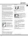
Зажигание газовых горелок
Вокруг каждой рукоятки управления горелкой указаны
символы, обозначающие силу пламени соответст-
вующей горелки.
Чтобы зажечь одну из горелок на рабочей поверх-
ности плиты:
1. Поднесите зажженную спичку или зажигалку
к горелке.
2. Нажмите рукоятку горелки, поверните ее против
часовой стрелки и установите в позицию макси-
мального пламени
.
3. Отрегулируйте интенсивность пламени, устано-
вив его желаемый уровень вращением рукоятки
против часовой стрелки. Рукоятку можно уста-
навливать в позиции: — минимальное пламя,
— максимальное пламя или в любое положение
между указанными позициями.
В моделях, имеющих ус-
тройство электронного
зажигания*(С), нажмите
кнопку электроподжига,
обозначенную симво-
лом , затем нажми-
те и поверните рукоятку
против часовой стрелки
к позиции максимального пламени, удерживайте ру-
коятку нажатой, пока пламя не загорится.
Некоторые модели оснащены устройством электрон-
ного зажигания, встроенным в рукоятку управления
горелкой, — в этом случае присутствует устройство
электронного зажигания* (см. рис.), но нет кнопки
электроподжига. Просто нажмите рукоятку горелки и
вращайте ее против часовой стрелки к позиции мак-
симального пламени, пока пламя не загорится.
При отпускании рукоятки пламя может погаснуть.
В этом случае повторите действия, удерживая руко-
ятку дольше нажатой.
! Если пламя случайно погасло, выключите горелку
и подождите не менее 1 минуты, прежде чем снова
зажечь ее.
В моделях, оснащенных
устройством безопасного
пламени (Х)*, нажмите и держите рукоятку горелки
нажатой примерно 2–3 секунды, чтобы удержать
горение пламени и активировать устройство.
Чтобы выключить горелку, поверните ее рукоятку до
упора и установите в положение «z» — выключено.
* Только для некоторых модификаций моделей.
Практические рекомендации по использованию
газовых горелок
Для наиболее эффективной работы газовых горелок
и экономного потребления газа используйте только
посуду с крышками и плоским дном. Также посуда
должна подходить по размеру к горелке.
Горелка Диаметр дна посуды, см
Быстрая (R) 24–26
Полубыстрая (S) 16–20
Вспомогательная (А) 10–14
Чтобы определить тип горелки, обратитесь к табл.
«Характеристики горелок и жиклеров».
Использование духовки
! Перед первым использованием в течение получа-
са прокалите пустую духовку с закрытой дверцей
при максимальной температуре. Прежде чем вы-
ключить оборудование и открыть дверцу, удостоверь-
тесь в наличии хорошей вентиляции в помещении.
Появившийся во время прокаливания неприятный
запах вызван сгоранием защитных веществ, исполь-
зуемых во время производства оборудования.
! Прежде чем
использовать оборудование, удалите
с его боковых сторон пластиковую пленку.
! Ничего не кладите на дно духовки — это может
повредить его эмалевое покрытие. Используйте 1-й
уровень духовки только при готовке на вертеле (при
его наличии).
Включение духовки
Чтобы зажечь горелку духов-
ки, поднесите горящую спичку
или зажигалку к отверстию «F»
(см. рис.),
нажмите и поверните
рукоятку управления духовкой
против часовой стрелки в поло-
жение Max.
Если спустя 15 секунд пламя не загорится, отпустите
рукоятку, откройте дверцу духовки и подождите не
менее 1 минуты, прежде чем снова зажигать пламя.
! Духовка оснащена устройством безопасности — для
его срабатывания рукоятку управления духовкой сле-
дует держать нажатой не менее 6 секунд.
! Если пламя неожиданно погаснет, выключите го-
релку и подождите не менее 1 минуты, прежде чем
снова зажигать ее.
Страница загружается ...
Страница загружается ...
Страница загружается ...
Страница загружается ...
Страница загружается ...
Страница загружается ...
Страница загружается ...
Страница загружается ...
Страница загружается ...
Страница загружается ...
Страница загружается ...
Страница загружается ...
Страница загружается ...
Страница загружается ...
Страница загружается ...
Страница загружается ...
-
 1
1
-
 2
2
-
 3
3
-
 4
4
-
 5
5
-
 6
6
-
 7
7
-
 8
8
-
 9
9
-
 10
10
-
 11
11
-
 12
12
-
 13
13
-
 14
14
-
 15
15
-
 16
16
-
 17
17
-
 18
18
-
 19
19
-
 20
20
-
 21
21
-
 22
22
-
 23
23
-
 24
24
-
 25
25
-
 26
26
-
 27
27
-
 28
28
-
 29
29
-
 30
30
-
 31
31
-
 32
32
-
 33
33
-
 34
34
-
 35
35
-
 36
36


Indesit MVK5 G1(W) RF Руководство пользователя
- Категория
- Аксессуары для кухни и посуды
- Тип
- Руководство пользователя
- Это руководство также подходит для
Задайте вопрос, и я найду ответ в документе
Поиск информации в документе стал проще с помощью ИИ
Похожие модели бренда
-
Indesit KN3G21S(X)/EU Руководство пользователя
-
-
-
-
-
-
-
-
Indesit C 34S G 37 RU /HA Руководство пользователя
-