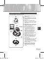
Samsung SCC-B5311BP Руководство пользователя
- Категория
- Видеокамеры наблюдения (охраны)
- Тип
- Руководство пользователя

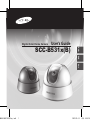
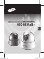
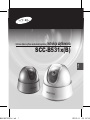
User’s Guide
SCC-B531x(B)
Digital Color Dome Camera
ENG
RUS
POL
AB68-00647E(00)Eng.indd 1 2007-05-14 ソタネト 4:46:24

2
3
This symbol indicates high voltage
is present inside. It is dangerous to
make any kind of contact with any
inside part of this product.
This symbol alerts you that important
literature concerning operation and
maintenance has been included with
this product.
To prevent damage which may result in fire
or electric shock hazard, do not expose this
appliance to rain or moisture.
WARNING
1. Be sure to use only the standard adapter
that is specified in the specification
sheet. Using any other adapter could
cause fire, electrical shock, or damage
to the product
2. Incorrectly connecting the power
supply or replacing battery may cause
explosion, fire, electric shock, or damage
to the product.
3.
Do not connect multiple cameras to a single
adapter. Exceeding the capacity may cause
abnormal heat generation or fire.
4. Securely plug the power cord into the
power receptacle. Insecure connection
may cause fire.
5. When installing the camera, fasten it
securely and firmly. A falling camera may
cause personal injury.
6.
Do not place conductive objects (e.g.
screwdrivers, coins, metal things, etc.) or
containers filled with water on top of the
camera. Doing so may cause personal injury
due to fire, electric shock, or falling objects.
7. Do not install the unit in humid, dusty, or
sooty locations. Doing so may cause fire
or electric shock.
8. If any unusual smells or smoke come
from the unit, stop using the product. In
such case, immediately disconnect the
power source and contact the service
center. Continued use in such a condition
may cause fire or electric shock.
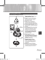
Safety Precautions
CAUTION: TO REDUCE THE RISK OF
ELECTRIC SHOCK, DO NOT REMOVE REAR
COVER. NO USER SERVICEABLE PARTS
INSIDE. REFER TO QUALIFIED SERVICE
PERSONNEL.
CAUTION
RISK OF ELECTRIC
SHOCK DO NOT OPEN
AB68-00647E(00)Eng.indd 2 2007-05-14 ソタネト 4:46:24

2
ENG
3
9. If this product fails to operate normally,
contact the nearest service center. Never
disassemble or modify this product
in any way. (SAMSUNG is not liable
for problems caused by unauthorized
modifications or attempted repair.)
10. When cleaning, do not spray water
directly onto parts of the product. Doing
so may cause fire or electric shock.
CAUTION
1. Do not drop objects on the product or
apply strong shock to it. Keep away from
a location subject to excessive vibration
or magnetic interference.
2. Do not install in a location subject to
high temperature (over 122°F), low
temperature (below 14°F), or high
humidity. Doing so may cause fire or
electric shock.
3. If you want to relocate the already
installed product, be sure to turn off the
power and then move or reinstall it.
4. Remove the power plug from the
outlet when then there is a lightning.
Neglecting to do so may cause fire or
damage to the product.
5. Keep out of direct sunlight and heat
radiation sources. It may cause fire.
6. Install it in a place with good ventilation.
7. Avoid aiming the camera directly towards
extremely bright objects such as sun,
as this may damage the CCD image
sensor.
8. Apparatus shall not be exposed to
dripping or splashing and no objects
filled with liquids, such as vases, shall be
placed on the apparatus.
9. The Mains plug is used as a disconnect
device and shall stay readily operable at
any time.
FCC Statement
This device complies with part 15 of the FCC
Rules. Operation is subject to the following
two conditions:
1) This device may not cause harmful
interference, and
2) This device must accept any interference
received including interference that may
cause undesired operation.
Note
This equipment has been tested and found to
comply with the limits for a Class A digital device,
pursuant to part 15 of FCC Rules. These limits
are designed to provide reasonable protection
against harmful interference when the equipment
is operated in a commercial environment. This
equipment generates, uses, and can radiate
radio frequency energy and, if not installed
and used in accordance with the instruction
manual, may cause harmful interference to radio
communications. Operation of this equipment
in a residential area is likely to cause harmful
interference in which case the user will be
required to correct the interference at his own
expense.
AB68-00647E(00)Eng.indd 3 2007-05-14 ソタネト 4:46:24

4
5
Important Safety Instructions
1. Read these instructions.
2. Keep these instructions.
3. Heed all warnings.
4. Follow all instructions.
5. Do not use this apparatus near water.
6. Clean only with dry cloth.
7. Do not block any ventilation openings.
Install in accordance with the
manufacturer’s instructions.
8. Do not install near any heat sources
such as radiators, heat registers, or
other apparatus (including amplifiers)
that produce heat.
9. Do not defeat the safety purpose of
the polarized or grounding-type plug.
A polarized plug has two blades with
one wider than the other. A grounding
type plug has two blades and a third
grounding prong. The wide blade or the
third prong is provided for your safety.
If the provided plug does not fit into
your outlet, consult an electrician for
replacement of the obsolete outlet.
10. Protect the power cord from being
walked on or pinched particularly at
plugs, convenience receptacles, and the
point where they exit from the apparatus.
11. Only use attachments/accessories
specified by the manufacturer.
12. Use only with cart, stand, tripod, bracket,
or table specified by the manufacturer, or
sold with the apparatus.
13. Unplug this apparatus. When a cart is
used, use caution when moving the
cart/apparatus combination to avoid
injury from tip-over.
14. Refer all servicing to qualified service
personnel. Servicing is required when
the apparatus has been damaged in any
way, such as power-supply cord or plug
is damaged, liquid has been spilled or
objects have fallen into the apparatus,
the apparatus has been exposed to rain
or moisture, does not operate normally,
or been dropped.
AB68-00647E(00)Eng.indd 4 2007-05-14 ソタネト 4:46:24

4
ENG
5
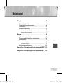
Overview ..................................................................................... 6
About this guide ............................................................................6
Product overview ...........................................................................6
Main features .................................................................................6
Components ...................................................................................6
Checking components in the package .......................................6
Components of your camera ......................................................7
Installation ................................................................................. 8
Setting switches ............................................................................8
Setting function switches ............................................................8
Connecting cables and setting switches ..................................10
Installing camera ......................................................................... 11
Before installation .....................................................................11
Installation procedure ............................................................... 11
Adjusting the camera direction ..................................................12
Appendix A: Specifications for NTSC Standard ........... 13
Appendix B: Specifications for PAL Standard ..............
15
Contents
AB68-00647E(00)Eng.indd 5 2007-05-14 ソタネト 4:46:25

6
7
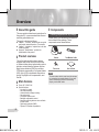
❚
About this guide
This user guide includes basic instructions for
the product. It is recommended that all users
read this guide before use.
This guide is divided as follows:
Chapter 1, “Overview,” introduces the user guide
and product related information. (This chapter)
Chapter 2, “Installation,” explains how to set and
install the product.
Appendix, “Specifications,” provides the
specifications of the product.
❚
Product overview
This is the high resolution dome camera
equipped with a fixed focal lens, which has
no dynamic delay when implementing motion
pictures, and provides the features such as
digital noise reduction (DNR) by real-time
CCD defect compensation, low speed shutter
(LSS: Auto x128) to implement clear picture
quality, Day/Night color compensation, and
the like.
❚
Main features
Power: DC 12V/AC 24V
Special functions
Line lock (LL) control
Auto white balancing
Horizontal/vertical image reversing
Auto gain control
Low shutter speed control
Backlight compensation control
Automatic switching between color and black
& white modes
Digital noise reduction (DNR)
Dynamic CCD defect compensation
❚
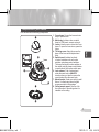
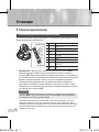
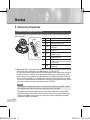
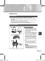
Components
Checking components in the package
Please check your camera and accessories
are included in the package. Those
components are as shown below:
Camera Test Monitor Cable
Tab screw User’s Guide
Note
The test monitor cable is used to test the camera
by connecting to a portable display. If you really
want to connect the camera to a monitoring
display, use the BNC cable.
Overview
AB68-00647E(00)Eng.indd 6 2007-05-14 ソタネト 4:46:25

6
ENG
7
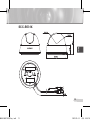
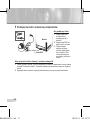
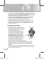
Components of your camera
Your camera has the following components:
1. Cover dome
: Covers the lens and main
body to protect them.
2. Main body
: Includes a lens, a switch
board, a PCB board, screws, and such.
3. Locker
: Used to open or close the Cover
dome. To open the cover dome, press the
locker.
4. Tilt fixing screw: Using this screw, the
slope of the lens can be adjusted and
fixed.
5. Switch board
: Includes two kinds
of control switches such as function
switches and phase-control switches.
The board has eight function switches in
the middle and two phase-control buttons
on each side of the function switch area.
6. Lock releaser
: Push it outward and
rotate the main body in UNLOCK
direction when you want to remove the
mount bracket from the main body.
7. Mount bracket
: Used as a ceiling or wall
fixture. It is fixed using three long tab
screws provided in the package.
8. Ceiling mount opener
: Remove it for
line connection to the ceiling when it is
installed on the ceiling.
1
Lens
2
3
4
5
6
7
8
AB68-00647E(00)Eng.indd 7 2007-05-14 ソタネト 4:46:28

8
9
❚
Setting switches
Setting function switches
To set the available functions on your camera, adjust eight switches as shown below:
Installation
No Name Brief description
1 LL Line lock ON/OFF
2 LSS Sens-up or Low speed shutter ON/OFF
3 H-REV Horizontal reverse ON/OFF
4 V-REV Vertical reverse ON/OFF
5 BLC Backlight compensation ON/OFF
6 AGC Auto gain control ON/OFF
7 D/N
Automatic switching between color and
black & white ON/OFF
8 AWB Automatic white balance ON/OFF
DEC
INC
8
7
6
5
4
3
2
1
1. Switch 1 (LL): When this switch is set to OFF, the camera operates in the internal
synchronization mode, while when it is set to ON, the camera operates in the line lock mode.
In the internal synchronization mode, the camera always uses an inside crystal oscillator for
synchronization. However if multiple cameras are connected to a sequential switcher, picture
rolling or flickering may occur when switching from one camera to another. In this case, you
can set this switch to ON to solve this problem.
The line lock mode allows the camera to use the phase of the AC power as the
synchronization reference. In this mode, you can use the phase control buttons(INC/DEC).
Note
When you are using the DC 12V power, set this switch to OFF. The line lock feature will not normally
operate even when the switch is set to ON.
Set the LL switch to ON while the AC power is connected. If any picture roll happens, you have
to adjust the phase using the phase-control buttons. Press the INC or DEC button to increase or
decrease the phase by one degree.
AB68-00647E(00)Eng.indd 8 2007-05-14 ソタネト 4:46:32

8
ENG
9
2. Switch 2 (LSS): This sens-up mode accumulates the image fields in memory to reduce
noise but increase the brightness and contrast rate. When this switch is set to ON, the
camera automatically switches to a maximum of 128 times of image acquisition speed to
implement a clear picture for darker image.
3. Switch 3 (H-REV): When this switch is set to ON, the camera image is reversed horizontally.
If you want to monitor your site using a mirror, you can use this feature to see the right
image.
4. Switch 4 (V-REV)
: When this switch is set to ON, the camera image is reversed vertically.
If your camera reluctantly displays the vertically reversed image, you can use this feature to
see the right image.
5. Switch 5 (BLC)
: When this switch is set to ON, you can view a clear image even though the
camera faces any excessive light such as sunlight and fluorescent light. When it is set to
OFF, the subject with excessive light is not clearly shown.
6. Switch 6 (AGC)
: When this switch is set to ON, the camera automatically increase the
sensitivity by amplifying the video signal when the strength of the signal falls below a given
value. When any dark images are expected, use this feature.
7. Switch 7 (D/N)
: When this switch is set to ON, the camera automatically switches between
color and B&W according to the brightness of the vicinity.
8. Switch 8 (AWB): This switch adjusts white balancing. When this switch is set to
ON, this
camera operates in ATW mode, and in case of
OFF, this camera operates in AWC mode.
ATW (Auto Tracking White Balance): The color temperature is automatically adjusted according to the
environmental change. (Approx. 2000°K to 11,000°K)
AWC (Auto White Balance Control): It stores the color temperature just when the switch is changed to
OFF. Accordingly color temperatures are adjusted by the stored value.
AB68-00647E(00)Eng.indd 9 2007-05-14 ソタネト 4:46:33

10
11
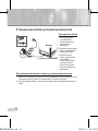
❚
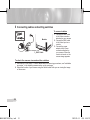
Connecting cables and setting switches
To connect cables
1. Connect the BNC cable
to the Video connector
attached on your camera.
2. Connect the BNC cable
to the Video Input on a
monitor.
3. Connect the power
adapter to the Power
connector attached on
your camera. When the
monitor is turned on, the
camera image appears.
To check the camera view and set the switches
1. Remove the Cover dome. For more details about the removing procedures, see “Installation
procedure,” in the Installing camera section on the next page.
2. Adjust the function of your camera using the Switch board while you are viewing the image
on the screen.
BNC Cable
Monitor
AB68-00647E(00)Eng.indd 10 2007-05-14 ソタネト 4:46:33

10
ENG
11
❚
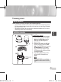
Installing camera
Before installation
Before installing your camera, you have to read the following cautions:
You have to check whether the location (ceiling or wall) can bear five times the weight of your camera.
Don’t let the cable to be caught in improper place or the electric line cover to be damaged. Otherwise it
may cause a breakdown or fire.
When installing your camera, don’t allow any person to approach the installation site. If you have any
valuable things under the place, move them away.
Installation procedure
To install your camera
1. Press the Locker button on the bottom
of your camera and remove the Cover
dome from the Main body using the
other hand. The Main body will be
exposed to you.
2. As shown in the picture, push the Lock
releaser outward and rotate the Main
body in the UNLOCK direction to remove
the Mount bracket. If it is not easily
done, rotate the Mount bracket in the
LOCK direction while holding small holes
on the Mount bracket.
3. Fix the Mount bracket to the location
(ceiling or wall) with supplied three
screws.
Note
The CAMERA FRONT sign on the Mount
bracket should face the camera monitoring
area.
1
Ceiling mount
opener
2
3
AB68-00647E(00)Eng.indd 11 2007-05-14 ソタネト 4:46:34

12
13
4. When you install the Mount bracket on the ceiling, remove the Ceiling mount opener by
pressing it hard to connect the line attached on your camera through the hole in the ceiling.
Otherwise, you can use the empty space opposite to the CAMERA FRONT sign for line
connection.
5. Now attach the Main body to the Mount bracket by rotating it in the LOCK direction after
aligning the Lock releaser on the Main body with the wide groove around the CAMERA
FRONT inlay.
6. Adjust the camera direction. For more details on the direction control, see “Adjusting the
camera direction,” on the same page.
7. Finally attach the Cover dome to the Main body by pressing it until a “click” sound is heard
after aligning the wide groove at the lower part of the Cover dome with the Locker on the
Main body.
❚
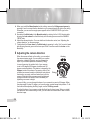
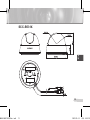
Adjusting the camera direction
When the camera is fixed on the ceiling, you can adjust
the camera viewing angle. You can rotate your camera
leftward or rightward (Panning), and can change the
slope of your camera upward or downward (Tilting).
In case of panning, the rotation limit of your camera
is set to 340 degree (220 degree clockwise and 120
degree counterclockwise). The rotation is stopped by the
Stopper inside of the camera. For panning control, first
unfasten two screws located on the bottom and rotate in
the direction you want, and then fasten them to fix the
camera. When both fixing screws cannot be tightened,
change the location of screws. When inevitable, just
tightening one screw is alright.
In case of tilting, you can change the slope of your camera from zero to 90 degree. When
the slope angle is under 23 degree, you can encounter a partial image hide problem. To fix
the location after adjusting the tilting angle, use the Tilt fixing screws.
To adjust the focus of your camera, rotate the fixed lens for clear image. When you install
the camera on the inclined ceiling or wall, you can rotate the camera lens to see a correct
direction image.
Panning
Tilting
Lens rotation
AB68-00647E(00)Eng.indd 12 2007-05-14 ソタネト 4:46:35

12
ENG
13
SCC-B531X
AB68-00647E(00)Eng.indd 13 2007-05-14 ソタネト 4:46:36

14
15
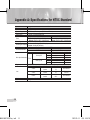
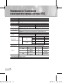
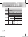
Appendix A: Specifications for NTSC Standard
Item Details
Product type CCTV color dome camera
Power input AC 24V ± 10% (60Hz ± 0.3 Hz), DC 12V +10%/-5%
Broadcast type NTSC Standard color system (525 Lines, 60 Fields)
Power consumption Approx. 1.6W
Image device 1/3 inch IT Type Super-HAD CCD
Pixels
SCC-B5311N, B5313N, B5315N
SCC-B5310N
Total: 811(H) x 508(V), 410,000 pixels
Effective: 768(H) x 494(V), 380,000 pixels
Total: 537(H) x 505(V), 270,000 pixels
Effective: 510(H) x 492(V), 250,000 pixels
Scanning mode 525 Lines, 2:1 Interlace
Scanning line frequency
Horizontal: 15.734Hz(INT)/15.750Hz(LL)
Vertical
: 59.94Hz(INT)/60Hz(LL)
Synchronization mode INT/Line Lock (Adjusting the phase using INC/DEC button)
Horizontal resolution
SCC-B5311N, B5313N, B5315N
SCC-B5310N
540 TV Lines 330 TV Lines
Min. object illumination
SCC-B5311N, B5313N, B5315N
SCC-B5310N
F2.0
Sens-up Off
50IRE 1Lux 0.6Lux
30IRE 0.6Lux 0.4Lux
15IRE 0.3Lux 0.2Lux
Sens-up x128
50IRE 0.008Lux 0.005Lux
30IRE 0.005Lux 0.003Lux
15IRE 0.002Lux 0.001Lux
Signal output
COMPOSITE Video(1
.
0 Vp-p, 75ohm, BNC), Test Monitor OUT(1
.
0 Vp-p, 75ohm, Harness cable)
Lens
Focal length Zone Limit of viewing angle Model
3.0mm
Horizontal
Vertical
92°
72°
SCC-B5313N
3.8mm
Horizontal
Vertical
71°
53°
SCC-B5310N,
B5311N
8.0mm
Horizontal
Vertical
33.6°
25.3°
SCC-B5315N
PAN function
Range: 0 to 340° (220 degree clockwise and 120 degree counterclockwise)
TILT function Range: 0 to 90°
AB68-00647E(00)Eng.indd 14 2007-05-14 ソタネト 4:46:38

14
ENG
15
Item Details
Controls
Line Lock (LL)
Sens-up; Low Speed Shutter(LSS)
Horizontal Reverse (H-REV)
Vertical Reverse (V-REV)
Backlight compensation (BLC)
Auto gain control (AGC)
Switching between color and B&W by day and night change (D/N)
Automatic white balancing (AWB)
Digital noise reduction (DNR)
Dynamic CCD defect compensation
Product color SCC-B531xN : White / SCC-B531xBN : Black
Operation temperature -10°C to +50°C
Operation humidity Up to 90%
Size 102(φ) x 78(H)mm
Weight
190g
AB68-00647E(00)Eng.indd 15 2007-05-14 ソタネト 4:46:38

16
17
Appendix B: Specifications for PAL Standard
Item Details
Product type CCTV color dome camera
Power input AC 24V ± 10% (50Hz ± 0.3 Hz), DC 12V +10%/-5%
Broadcast type PAL Standard color system (625 Lines, 50 Fields)
Power consumption Approx. 1.6W
Image device 1/3 inch IT Type Super-HAD CCD
Pixels
SCC-B5311P, B5313P, B5315P
SCC-B5310P
Total
: 795(H) x 596(V), 470,000 pixels
Effective: 752(H) x 582(V), 440,000 pixels
Total: 537(H) x 597(V), 320,000 pixels
Effective: 500(H) x 582(V), 290,000 pixels
Scanning mode 625 Lines, 2:1 Interlace
Scanning line frequency
Horizontal: 15.625Hz(INT)/15.625Hz(LL)
Vertical
: 50Hz(INT)/50Hz(LL)
Synchronization mode INT/Line Lock (Adjusting the phase using INC/DEC button)
Horizontal resolution
SCC-B5311P, B5313P, B5315P
SCC-B5310P
540 TV Lines 330 TV Lines
Min. object illumination
SCC-B5311P, B5313P, B5315P
SCC-B5310P
F2.0
Sens-up Off
50IRE 1Lux 0.6Lux
30IRE 0.6Lux 0.4Lux
15IRE 0.3Lux 0.2Lux
Sens-up x128
50IRE 0.008Lux 0.005Lux
30IRE 0.005Lux 0.003Lux
15IRE 0.002Lux 0.001Lux
Signal output
COMPOSITE Video(1
.
0 Vp-p, 75ohm, BNC), Test Monitor OUT(1
.
0 Vp-p, 75ohm, Harness cable)
Lens
Focal length Zone Limit of viewing angle Model
3.0mm
Horizontal
Vertical
92°
72°
SCC-B5313P
3.8mm
Horizontal
Vertical
71°
53°
SCC-B5310P,
B5311P
8.0mm
Horizontal
Vertical
33.6°
25.3°
SCC-B5315P
PAN function
Range: 0 to 340° (220 degree clockwise and 120 degree counterclockwise)
TILT function
Range: 0 to 90°
AB68-00647E(00)Eng.indd 16 2007-05-14 ソタネト 4:46:38

16
ENG
17
Item Details
Controls
Line Lock (LL)
Sens-up; Low Speed Shutter(LSS)
Horizontal Reverse (H-REV)
Vertical Reverse (V-REV)
Backlight compensation (BLC)
Auto gain control (AGC)
Switching between color and B&W by day and night change (D/N)
Automatic white balancing (AWB)
Digital noise reduction (DNR)
Dynamic CCD defect compensation
Product color SCC-B531xP : White / SCC-B531xBP : Black
Operation temperature -10°C to +50°C
Operation humidity Up to 90%
Size 102(φ) x 78(H)mm
Weight
190g
AB68-00647E(00)Eng.indd 17 2007-05-14 ソタネト 4:46:38

AB68-00647E(00)Eng.indd 18 2007-05-14 ソタネト 4:46:38

Correct Disposal of This Product
(Waste Electrical & Electronic Equipment)
(Applicable in the European Union and other European countries with separate
collection systems)
This marking shown on the product or its literature, indicates that it should
not be disposed with other household wastes at the end of its working life. To
prevent possible harm to the environment or human health from uncontrolled
waste disposal, please separate this from other types of wastes and recycle it
responsibly to promote the sustainable reuse of material resources.
Household users should contact either the retailer where they purchased this
product, or their local government office, for details of where and how they can
take this item for environmentally safe recycling.
Business users should contact their supplier and check the terms and conditions
of the purchase contract. This product should not be mixed with other commercial
wastes for disposal.
AB68-00647E(00)Eng.indd 19 2007-05-14 ソタネト 4:46:38

AB68-00647E(00)Eng.indd 20 2007-05-14 ソタネト 4:46:38
Страница загружается ...
Страница загружается ...
Страница загружается ...
Страница загружается ...
Страница загружается ...
Страница загружается ...
Страница загружается ...
Страница загружается ...
Страница загружается ...
Страница загружается ...
Страница загружается ...
Страница загружается ...
Страница загружается ...
Страница загружается ...
Страница загружается ...
Страница загружается ...
Страница загружается ...
Страница загружается ...
Страница загружается ...
Страница загружается ...
Страница загружается ...
Страница загружается ...
Страница загружается ...
Страница загружается ...
Страница загружается ...
Страница загружается ...
Страница загружается ...
Страница загружается ...
Страница загружается ...
Страница загружается ...
Страница загружается ...
Страница загружается ...
Страница загружается ...
Страница загружается ...
Страница загружается ...
Страница загружается ...
Страница загружается ...
Страница загружается ...
Страница загружается ...
-
 1
1
-
 2
2
-
 3
3
-
 4
4
-
 5
5
-
 6
6
-
 7
7
-
 8
8
-
 9
9
-
 10
10
-
 11
11
-
 12
12
-
 13
13
-
 14
14
-
 15
15
-
 16
16
-
 17
17
-
 18
18
-
 19
19
-
 20
20
-
 21
21
-
 22
22
-
 23
23
-
 24
24
-
 25
25
-
 26
26
-
 27
27
-
 28
28
-
 29
29
-
 30
30
-
 31
31
-
 32
32
-
 33
33
-
 34
34
-
 35
35
-
 36
36
-
 37
37
-
 38
38
-
 39
39
-
 40
40
-
 41
41
-
 42
42
-
 43
43
-
 44
44
-
 45
45
-
 46
46
-
 47
47
-
 48
48
-
 49
49
-
 50
50
-
 51
51
-
 52
52
-
 53
53
-
 54
54
-
 55
55
-
 56
56
-
 57
57
-
 58
58
-
 59
59


Samsung SCC-B5311BP Руководство пользователя
- Категория
- Видеокамеры наблюдения (охраны)
- Тип
- Руководство пользователя
Задайте вопрос, и я найду ответ в документе
Поиск информации в документе стал проще с помощью ИИ
на других языках
Похожие модели бренда
-
Samsung SCC-B5392P Руководство пользователя
-
-
-
-
-
Samsung SCC-B2313P Руководство пользователя
-
-
-
-