Kuppersberg FV3XE Руководство пользователя
- Категория
- Кухонные плиты (варочные панели)
- Тип
- Руководство пользователя

TECHNICAL PASSPORT
ПАСПОРТ ТЕХНИЧЕСКОГО ИЗДЕЛИЯ
MIXED AND GAS FUELLED BUILT-IN HOT PLATES
КОМБИНИРОВАННЫЕ ВАРОЧНЫЕ ПОВЕРХНОСТИ
FV3XE, FV3TGX

2
TECHNICAL PASSPORT ENGLISH
Mixed and gas fuelled built-in hot plates
1. APPEAL TO THE CUSTOMER
Dear Customer,
Thank you for having purchased one of our products.
We are certain that this new, modern, functional and practical appliance, built
with the very highest quality materials, will meet your requirements in the best
possible way. This appliance is easy to use. it is, however, important to thoroughly
read the instructions in this handbook in order to obtain the best results.
The manufacturer shall not be held responsible for any damages to persons or
property caused by incorrect installation or use of the appliance .
The Manufacturer shall not be held responsible lor any inaccuracies in this
handbook due to printing or transcription errors; the designs in the gures are purely
indicative. The Manufacturer also reserves the right to make any modi cations to
the products as may be considered necessary or useful, also in the interests of the
user, without jeopardizing the main functional and safety features of the products
themselves.
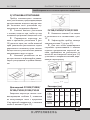
FV3XG/FV3EG/FV3XW/FV3EG
FV3XE/FV3EE
1 Ultra rapid burner of 3350W
2 Rapid gas burner of 3000W
3 Auxiliary gas burner of 1000 W
4 Electric plate
145 mm of 1000-1500 W
5 Electric plate
180 mm of 1500 -2000 W
6 Enamelled steel pan support 1 F
7 Enamelled sıeel pan support 2F
8 Burner n° 1 control knob
9 Burner n° 3 control knob
10 Burner n° 2 control knob
11 Electric plate n° 5 control knob
12 Electric plate n° 4 control knob
13 Electric plate operation warning light
14Timer
TECHNICAL CHARACTERISTICS AND DRAWINGS

3
ENGLISH TECHNICAL PASSPORT
Mixed and gas fuelled built-in hot plates
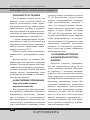
FV3VR/FV3VR
FV3TG X FV3XE
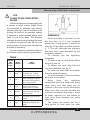
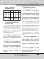
1 Hi-light electric heating element
140 mm 1200 W
2 Hi-light electric heating element
180 mm 1800 W
3 Hi-light electric heating element double
cooking zone (conc.)
180/120 mm 1700 W
(«Hilight» as well)
4 Hi-light electric heating element double
cooking zone (oval)
265/170 mm 2200 W
5 Switch for el. element n.2
6 Switch tor el. element n.1
7 Switch for el. element n.3
8 Switch for el. element n.4
9 Residual heat indicator

4
TECHNICAL PASSPORT ENGLISH
Mixed and gas fuelled built-in hot plates
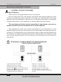
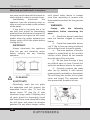
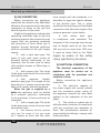
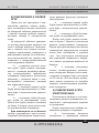
1) ELECTRIC HOB
(for ceran glass products)
The hot plates are equipped with 2
hi-light heating elements with different
powers and diametres. On the frontal
panel, close to each knob, has been silk-
screened a scheme where is indicated to
which cooking zone the knob refers (g. 2).
In some particular models the scheme
annexes a light indicator that turns on
when the cooking zome temperature is
above 60 C.
The indicator will turn off only when
the temperature of the cooking zone will
be below the value: thes is the reason why
we call it residual heat indicator. Some
other models they have only one indicator.
Connection of electric heating
elements
Heating elements are controlled by
energy regulators that permit to obtain a
big range of different temperatures.
To connect the heating elements
es necessary to turn clockwise or
anticlockwise the relaive knob. Indicator
light 9 shows the connection of one or
more heating elements.
To connect the heating elements with
double cooking zone is necessary to turn
clockwise the knob to the «Ф1 sign and
release again.
How to use the cooking zones
Heating takes place only in the inside
part of the circles drawn on the special
glass. The circles have to be wholly
covered by the pots.
WARNINGS:
For a correct use, please look at g.3
and remind:
B Switch on the electricity
only after having placed the pot on the
cooking zone.
B Use pots and pans with at
solid bottoms.
B Use pots with the same
diameter of the cooking zones.
B Dry the bottom of the pot
before put in on the cooking zones.
B Do not scrape the pot against
the glass so to not damage it.
B During the use of the cooking
zones, please, keep the children away
from the hot plates. Make sure that the
handles of the pots are placed in the
right way towards the interior. Be aware
that overheated fats and oils may become
inamed.
B Cooking zones after using
remain warm; don’t leave objects, don’t
lean your hands so to avoid burns, till the
indicator light is off.
B If the glass cracks, please,
disconnect the appliance.
B Don’(use plastic pots or
alluminium sheets.
B Don’t use hob as a
supplementary surface.

5
ENGLISH TECHNICAL PASSPORT
Mixed and gas fuelled built-in hot plates
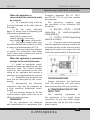
NORMAL
AND
RAPID
PLATES
HEAT
INTENSITY
HEAT
INTENSITY
0
Off
1 Weak
To dissolve butter,
chocolate, etc.. To heat
small amounts of liquid.
2
Low
To heat larger amounts of
liquid. To prepare cremes
and suces requiring long
slow cooking times.
3
Slow
To thaw frozen foods and
prepare stews, heat to
boiling point or simmer.
4
Medium
To heat foods to boiling
point. To brown delicate
meats and sh.
5
Strong
For escalopes and steaks.
To simmer large amounts
of food.
6
High
To bring large amounts
of liquid to the boil. For
frying.
USE
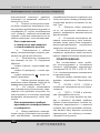
2) HOW TO USE THE ELECTRIC
PLATES
Mixed hot plates may be equipped with
a normal or rapid electric plates. There
are controlled by switches with various
positions (see g. 4 ) and is switched on by
turning the knob to the required setting.
A diagram is screen-printed above each
knob on the front panel. This diagram
indicates to which electric plates the knob
in question corresponds (see g. 4). A red
warning light will come on to indicate that
the plate is operating.
A purely indicative regulation table for
the normal electric plates is given below.
TABLE
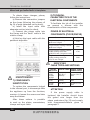
WARNINGS;
When the plate is switched on for
the rst time, or if it has remained
unused for a long period, it should be
dried for 30 minutes on switch position
n° 1. This will eliminate any moisture
that may have been absorbed by the
insulating material.
To correctly use the appliance,
remember
To place a pan on the plate before
switching this on.
To always use pans with at and
very thick bottoms (see g. 5).
To never use pans that are smaller
than the plate diameters.
To dry the bottom of the pan before
placing it on the plate.
Never leave the appliance
unattended when the plates are being
used. Make sure that there are no
children in the near vicinity. Particularly
make sure that the pan handles are
correctly positioned and keep a check
on foods requiring oil and grease to
cook since these products can easily
catch re.
The plates will remain hot for a
long period of time even use after

6
TECHNICAL PASSPORT ENGLISH
Mixed and gas fuelled built-in hot plates
use, never touch them with the hands or
other objects in order to prevent bums.
Immediately disconnect the
appliance from the electricity main as
soon as cracks are noted on the surfaces
of the plates.
If the built-in hot plate has a lid,
any spilt food should be immediately
removed from this before it is opened. If
the appliance has a glass lid, this could
shatter when the cooker becomes hot.
Always switch off all the plates before
closing the lid.
IMPORTANT:
Always disconnect the appliance
from the gas and electricity mains
before carrying out any cleaning
operation.
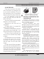
CLEANING
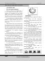
3) HOT PLATE
Periodically wash the hot plate,
the enamelled stell pan support, the
enamelled burner caps “C» and the
burner heads “M” (see g. 6) with
lukewarm soapy water. Following this,
all parts should be thoroughly rinsed
and dried. Never wash them while they
are still warm and never use abrasive
powders. Do not allow vinegar, coffee,
milk, salted water, lemon or tomato
juice from remaining in contact with
the enamelled surfaces for long periods
of time.
WARNINGS:
Comply with the following
instructions, before remounting the
parts:
B Check that burner head slots
have not become clogged by foreign
bodies.
B Check that enamelled burner
cap “C” ( g. 6) have correctly positioned
on the burner head. It must be steady.
B The exact position of the pan
support is established by the rounded
corners, which should be set towards
the side edge of the hot plate.
B Do not force the taps if they
are dif cult open or close. Contact the
technical assistance service for repairs.
B Correctly preserve the plate
after use by treating it with special
products, easily available on the market.
This will keep the surface of the plate
clean and bright. The operation will
also prevent the formation of rust.

7
ENGLISH TECHNICAL PASSPORT
Mixed and gas fuelled built-in hot plates
2) ELECTRIC HOB
lf you want to preserve the surface
clean and bright, we recommend you
to use a silicone conditioner. The use of
this conditioners, prior to jam-making,
helps to protect the surface of the hob.
It is very important to clean the
surface soon after every use, when the
glass is stili tepid.
Do not use metallic sponges, powder
abrasives or corrosive sprays.
Depending on the dirty level we
recommend:
 Slights stains: it is enought the
use of a moist clean rag.
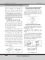
 Burnt or soiling may be removed
with a special razor scraper ( g. 7 ); be
aware that the razor can cause wounds.
 Marks of liquid, over owed from
the pot, can be removed using vinegar
or lemon.
 Pay attention to not /et fail sugar
or element with sugar. in this case turn
the swithch off and clean the surface
with hot water and the razor b/ade
scraper.
 After a period of time may appear
metal re ex and scratches ( g. 8) due to
the wrong cleaning and the wrong use
of the pots. The scratches are dif cultly
removable, but they do not compromise
!he good working of the hob.
SAFETY INSTALLATION
TECHNICAL INFORMATION FOR
THE INSTALLER
Installation, adjustments of controls
and maintenance must only be carried
out by a quali ed engineer.
Incorrect installation may cause
damage to persons, animals or property
for which the Manufacturer shall not be
considered responsible.
During the life of the system, the
automatic safety or regulating devices
on the appliance may only be modi ed
by the manufacturer or by his duly
authorized dealer.
4) INSTALLING THE HOT PLATE
Check that the appliance is in a good
condition after having removed the
outer packaging and internal wrappings
from around the various loose parts. In
case of doubt, do not use the appliance
and contact quali ed personnel.
Never leave the packaging materials
(cardboard, bags, polystyrene foam,
nails, etc.) within childrens reach since
they could become potential sources of
danger.
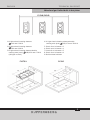
The measurements of the opening
made in the top of the modular

8
TECHNICAL PASSPORT ENGLISH
Mixed and gas fuelled built-in hot plates
cabinet and into which the hot plate
will be installed are indicaled in
either g. 9. Always comply with the
measurements given for the hole into
which Ihe appliance will be recessed.
The appliance belongs to class 3 and
is therefore subject to all the provisions
established by the provisions governing
such appliances.
5) SEALING THE HOT PLATE
The hot plate has a special seal
which prevents liquid from in ltrating
into the cabinet. Strictly comply with
the following instructions in order to
correctly apply this seal:
 Detach the seals from their
backing, checking that the transparent
protection still adheres to the seal itself.
 Overturn Ihe hol plate and
correctly position seal “E” ( g. 1O) under
the edge of the hol plate itself, so that
the outer side of the seal perfectly
matches the outer perimetral edge of
the hol plate. The ends of the strips
must t together without overlapping.
 Evenly and securely x the seal
to the hot plate, pressing it in place
with the ngers.
For the models FV3XW/FV3EW/
FV3XG/FV3EG/FV3XE/FV3GE
Fix the hob with the proper bracets
«S» and t the prominent part into the
porhole «H» on the bottom; turn the
screw «F» until the bracket «S» stick on
the top (fıg.11)
FV3VR/FM3VR/FV3XF/FV3XB
 Remove the clamps «G» from the
package and install !hem according to
the diagram in fıg.12.
 Secure the appliance by
thigtening the clamp screws «F» (see
fıg.13).
 In order to prevent any accidental
contact with the suıface of the heated
bbarbecue during use, a separation in
wood must be inserted and fastened
with screws at a minimum distance of
60 mm from the top ( g.14).

9
ENGLISH TECHNICAL PASSPORT
Mixed and gas fuelled built-in hot plates
COMPL Y WITH THE
DIMENSIONS (mm)
Product A B С D E
FV3X6
F3E6
FV3XW
FV3EW
FV3XE
FV3EG
280 480 57.5 57.5
min
100
FV3VR
FM3VR
285 485 60 60
min
60
IMPORTANT INSTALLATION
SPECIFICATIONS
The installer should note that the
appliance that side walls should be
no higher than the hot plate itself.
Furthermore, the rear wall, the surfaces
surrounding and adjacent to the
appliance must be able to withstand an
overtemperature of 65 K.
The adhesive used to stick the
plastic laminate to the cabinet must be
able to withstand a temperature of not
less than 150° C otherwise the laminate
could come unstuck.
The appliance must be installed in
compliance with the provisions in force.
This appliance is not connected to a
device able to dispose of the combustion
fumes. It must therefore be connected in
compliance with the above mentioned
installation standards. Particular
care should be paid to the following
provisions governing ventilation and
aeration.
6) ROOM VENTILATION
(for gas product)
It is essential to ensure that the
room in which the appliance is installed
is permanently ventilated in order to
allow the appliance itself to operate
correctly. The necessary amount of air is
that required lor regular gas combustion
and ventilation of the relative room, the
volume of which must not be less than
20 m
3
. Air must naturally ow through
permanent openings in the walls of the
room in question. These openings must
vent the fumes outdoors and their section
must be at least 100 cm
2
Construction
of the openings must ensure that the
openings themselves may never be
blocked. Indirect ventilation by air drawn
from an adjacent room is also permitted,
in strict compliance with the provisions
in force.
7) LOCATION AND AERATION
Gas cooking appliances must
always dispose of their combustion
fumes through hoods. These must be
connected to ues, chimneys or straight
outside. lf it is not possible to install a
hood, an electric fan can be installed on
a window or on a wall facing outside.
This must be activated at the same
time as the appliance, so long as the
speci cations in the provisions in force
are strictly complied with.

10
TECHNICAL PASSPORT ENGLISH
Mixed and gas fuelled built-in hot plates
8) GAS CONNECTION
Before connecting the appliance,
check that the values on the data label
afxed to the underside of the hot plate
correspond to those of the gas and
electricity mains in the home.
A label on the appliance indicates the
regulating conditions: type of gas and
«working pressure. Gas connection must
comply with the pertinent standards
and provisions in force. When gas is
supplied through ducts,the appliance
must be connected to the gai> supply
system:
B with a rigid steel pipe. The
joints of this pipe must consist of
threaded ttings conforming to the
standards. Use of seals such as heinp
with suitable cement, or Teon tape, is
permitted;
B with copper pipe. The joints
of this pipe must consist of unions with
mechanical seals;
B with seamless exible
stainless steel pipe. The length of this
pipe must be 2 meters at most and the
seals must comply with the standards.
When the gas is supplied by a
bottle the appliance must be fuelled
by a pressure (governor conforming
to the provisions in force and must be
connected:
B with a copper pipe. The joints
of this pipe must consist of unions with
mechanical seals;
B with seamless exible stainless
steel pipe. The length of this pipe
must
be 2 meters at most and the seals
must comply with the standards. it is
advisable to apply the special adapter
to the exible pipe. This is easily
available from the shops and facilitates
connection with tlhe hose nipple of the
pressure governor on the bottle.
B with rubber hose pipe
in compliance with standards. The
diameter of this hose pipe must be mm
and its length must be no less than
400 mm and no more than 1500 mm.
It must be rmly xed to the
hose
nipple by means of the safety
clamp specied by standards.
9) ELECTRICAL CONNECTION
The electrical connections of the
appliance must be carried out in
compliance with the provisions and
standards in force.
Before connecting the appliance,
check that:
B The electrical capacity of
the mains supply and current sockets
suit the maximum power rating of
the appliance (consult the data label
applied to the underside of the hot
plate).
B The socket or system has an
efcient earth connection in compliance
with the provisions and standards in
force. The manufacturer declines all
responsibility for failing to comply with
these provisions.

11
ENGLISH TECHNICAL PASSPORT
Mixed and gas fuelled built-in hot plates
When the appliance is
connected to the electricity main
by a socket
B Fit a standard plug suited to
the load indicated on the data label to
the cable.
B Fit the wires following
gure 15, taking care of respecting the
following correspondences:
letter L (live) = brown wire;
letter N (neutral) = blue wire;
earth symbol
= green - yellow wire.
B The power supply cable must
be positioned so that no part of it is able
to reach an overtemperature of 75 K.
B Never use reductions, adapters
of shunts for connection since these
could create false contacts and lead to
dangerous overheating.
When the appliance is connected
straight to the electricity main:
B lnstall an omnipolar circuit-
breaker between the appliance and the
electricity main. This circuit- breaker
should be sized according to the load
rating of the appliance and possess a
minimum 3 mm gap between its contacts.
B Remember that the earth wire
must not be interrupted by the circuit-
breaker.
B Alternatively, the electrical
connection may also be protected by
a high sensitivity differential circuit-
breaker.
You are strongly advised to x the
relative yellow- green earth wire to an
ef cient earthing system.
WARNINGS:
All our appliances are designed
and manufactured in compliance with
European standards EN 60 335-1
and EN 60 335-2-6 plus the relative
amendments.
The appliance complies with
the provisions of the following EEC
Directives:
B 89/336 + 92/31 + 93/68
regarding to electromagnetic
compatibility.
B 73123 + 93168 regarding
electrical safety.
B If a power card is not supplied
with the appliance, connect a cable with
a suitable section to the terminal board,
keeping the earth wire longer than the
lead wires. (see the table in this manual).
TRANSFORMATIONS
Always disconnect the appliance
from the electricity and gas mains
before proceeding with any operation
6) TRANSFORMATION OF THE
INPUT TYPE
The standard equipment of
the appliances is for single phase
connection. In any case, under proper
changes, they can be fed with a three
phase system.

12
TECHNICAL PASSPORT ENGLISH
Mixed and gas fuelled built-in hot plates
To obtain these changes, please,
follow the instructions:
a) Remove the connection jumpers
on the clamp following the scheme of
g. 16 of page (attached on the body).
b) Insert the input cable with
adequate section into the chock.
c) Connect the phase cable into
the clamp and the “earth” cable in the
relative clamp.
d) Hold up the input cable with the
pertinent stopcable.
8) TECHNICAL
CHARACTERISTICS OF THE
ELECTRICAL COMPONENTS
To facilitate the job of the installer
we present a scheme with the
characteristics of the components.
Denominations W
Hi-light electric heating element
140 mm "Hilight”
1200
Hi-light electric heating element
180 mm "Hilight"
1800
Hi-light electric heating element
double cooking zone conc.
180/120 mm ("Hilight" as well)
1700
Hi-light electric heating element
double cooking zone oval
265/170 mm "Hilight"
2400
POWER OF ELECTRICAL
COMPONENTS (FV3VR/FM3VR)
MAINTENANCE
7) COMPONENTS
SUBSTITUTION
To replace the components lodged
in the internal part, is necessaryto take
the appliance up from the furniture,
overturn it, loosen the sorews and take
away the bottom.
After these actions is possible
to work on the plates, commutators,
clamps and input cable.
SERVICING
CABLE TYPES AND SECTIONS
TYPE OF
HOT PLATE
TYPE OF CABLE
SINGLE - PHASE
POWER SUPPLY
FV3XG/
FV3EG
FV3XW/
FW3EW
H05 RR - F
(Rubber)
Section 3 X 0.75
mm
2
FV3XE
FV3EE
H05 RR - F
Rubber)
Section 3 X 1.5
mm
2
FV3VR/
FM3VR
H05 RR - F
Section 3 X 1.5
mm
2
ATTENTION
If the power supply cable is
leplaced, the Installer should leave
the gound wire longer than the
phase conductors ( g. 26) and comply
with theecommendations given in
paragraph 9.

13
ENGLISH TECHNICAL PASSPORT
Mixed and gas fuelled built-in hot plates
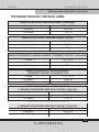
TECHNICAL DATA ON THE DATA LABEL
MODEL FV3XE/FV3EE 2 HEATING ELEMENT (STANDARD)
Voltage 230 • 240 V
Frequency 50/60 Hz
Tot. Rating 2500 w
MODEL FV3XE/ FM3EE 2 HEATING ELEMENT (RAPID)
Voltage 230 - 240 V
Frequency 50/60 Hz
Tot. Rating 3500 w
MODEL FV3VR/FM3VR 2 HEATING ELEMENT (2 RADIANTS "HILIGHT" d140+d180)
Voltage 230 - 240 V
Frequency 50/60 Hz
Tot. Rating 3000 w
MODEL FV3VR/FM3VR 2 HEATING ELEMENT
(2 RADIANTS "HILIGHT" d140+d180/120)
Voltage 230 - 240 V
Frequency 50/60 Hz
Tot. Rating 2900 w
MODEL FV3VR/FM3VR 1 HEATING ELEMENT
(1 RADIANT WITH DOUBLE ZONE OVAL "HILIGHT" d180/120)
Voltage 230 - 240 V
Frequency 50/60 Hz
Tot. Rating 1700 w
MODEL FV3VR/FM3VR 1 HEATING ELEMENT
(1 RADIANT WITH DOUBLE ZONE OVAL "HILIGHT" d265/170)
Voltage 230 - 240 V
Frequency 50/60 Hz
Tot. Rating 2200 w

14
ПАСПОРТ ТЕХНИЧЕСКОГО ИЗДЕЛИЯ РУССКИЙ
Комбинированные и газовые варочные поверхности
1. ОБРАЩЕНИЕ К ПОКУПАТЕЛЯМ
Уважаемый покупатель!
Благодарим вас за приобретение нашей продукции.
Мы уверены, что этот новый, современный, функциональный и практичный
прибор, изготовленный из высококачественных материалов, в максимальной
мере будет отвечать всем вашим требованиям. Данный прибор очень прост в ис-
пользовании, тем не менее, вам необходимо внимательно изучить содержание
настоящей инструкции, что позволит вам обеспечить максимальную эффектив-
ность работы с ним.
Компания-изготовитель не несет никакой ответственность за любой ущерб
людям, животным или имуществу, который может быть нанесен вследствие не-
правильной установки или эксплуатации прибора.
Компания-изготовитель не несет никакой ответственности за любые неточно-
сти, которые могут содержаться в данной инструкции в связи с возникновением
ошибок в процессе печати или набора текста; все приведенные изображения
носят исключительно иллюстративный характер. Компания-изготовитель также
оставляет за собой право вносить любые изменения в продукцию, которые она
посчитает необходимыми или полезными, в том числе в интересах пользователей,
без ущерба для основной функциональности и безопасности самой продукции.
ТЕХНИЧЕСКИЕ ХАРАКТЕРИСТИКИ И ЧЕРТЕЖИ
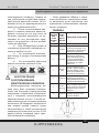
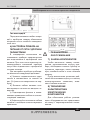
FV3XG/FV3EG/FV3XW/FV3EG
FV3XG/FV3EG/FV3XW/FV3EG
FV3XE/FV3EE
1 Сверхбыстрая газовая конфорка мощностью
3350 Вт
2 Быстрая газовая конфорка мощностью 3000 Вт
3 Вспомогательная газовая конфорка мощностью
1000 Вт
4 Электрическая конфорка Ø 145 мм и мощностью
1000–1500 Вт
5 Электрическая конфорка Ø 180 мм и мощностью
1500–2000 Вт
6 Решетка из эмалированной стали 1 F
7 Решетка из эмалированной стали 2F
8 Ручка управления газовой конфоркой 1
9 Ручка управления газовой конфоркой 3
10 Ручка управления газовой конфоркой 2
11 Ручка управления электрической конфоркой 5
12 Ручка управления электрической конфоркой 4
13 Сигнальный индикатор работы электрической
конфорки
14 Таймер

15
РУССКИЙ ПАСПОРТ ТЕХНИЧЕСКОГО ИЗДЕЛИЯ
Комбинированные и газовые варочные поверхности
FV3VR/FV3VR
1 Электрический нагревательный элемент
Hi-light
140 мм, мощность 1200 Вт
2 Электрический нагревательный элемент
Hi-light
180 мм, мощность 1800 Вт
3 Электрический нагревательный элемент (двух-
контурная конфорка с концентрическими
зонами нагрева)
180/120 мм, мощность 1700
Вт (также тип Hilight)
4 Электрический нагревательный элемент (кон-
форка с овальной зоной нагрева)
265/170
мм, мощность 2200 Вт
5 Переключатель для включения эл. элемента № 2
6 Переключатель для включения эл. элемента № 1
7 Переключатель для включения эл. элемента № 3
8 Переключатель для включения эл. элемента № 4
9 Индикатор остаточного тепла
FV3TG X FV3XE

16
ПАСПОРТ ТЕХНИЧЕСКОГО ИЗДЕЛИЯ РУССКИЙ
Комбинированные и газовые варочные поверхности
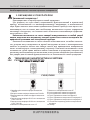
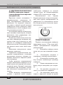
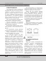
1) ЭЛЕКТРИЧЕСКАЯ ВАРОЧНАЯ
ПАНЕЛЬ (некоторые модели
стеклокерамических варочных
поверхностей)
Варочные панели оснащаются 2
нагревательными элементами Hi-
light, отличающимися мощностью и
диаметром. На передней поверхно-
сти рядом с каждой ручкой методом
трафаретной печати нанесены схемы,
указывающие, к какой конфорке отно-
сится каждая ручка (рис. 2).
В некоторых моделях схема допол-
нена световым индикатором, который
включается, если температура кон-
форки превышает 60 С.
Индикатор гаснет только в том слу-
чае, если температура конфорки опу-
скается ниже этого значения, по этой
причине он называется индикатором
остаточного тепла. В некоторых моде-
лях имеется только один такой инди-
катор.
Включение электрических нагре-
вательных элементов
Управление нагревательными эле-
ментами осуществляется с помощью
регуляторов мощности, которые по-
зволяют обеспечить широкий диапа-
зон температур.
Чтобы включить нагревательный
элемент, необходимо повернуть по ча-
совой стрелке или против нее соответ-
ствующую ручку. Световой индикатор
9 загорается при включении одного
или нескольких нагревательных эле-
ментов.
Чтобы включить нагревательный
элемент с двойной зоной нагрева,
необходимо повернуть по часовой
стрелке ручку до соответствующего
символа «Ф1 и отпустить ее снова.
Использование зон нагрева
Нагрев происходит только во внутрен-
ней части кругов, изображенных на
поверхности из специального стекла.
Дно посуды должно полностью закры-
вать эти круги.
рис. 2
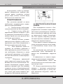
ПРЕДУПРЕЖДЕНИЯ:
Порядок использования конфорки
представлен на рис. 3. При этом необ-
ходимо придерживаться следующих
рекомендаций:
B Включайте конфорку только
после того, как нее помещена кастрю-
ля.
B Используйте кастрюли и
сковороды с плоским толстым дном.
B Используйте кастрюли, раз-
мер которых соответствует диаметру
конфорки.
B Перед помещением на кон-
форку насухо вытирайте дно кастрю-
ли.
B Не двигайте кастрюлю по
стеклу это может его повредить.
B Не позволяйте детям под-
ходить к варочной панели во время

17
РУССКИЙ ПАСПОРТ ТЕХНИЧЕСКОГО ИЗДЕЛИЯ
Комбинированные и газовые варочные поверхности
использования конфорок. Следите за
тем, чтобы ручки посуды были направ-
лены внутрь варочной панели. Не за-
бывайте о том, что перегретые масло и
жиры могут воспламениться.
B После использования кон-
форки остаются некоторое время го-
рячими; поэтому до тех п ор, пока не
погаснет световой индикатор, не по-
мещайте на них посторонние пред-
меты и не опирайтесь на них руками,
чтобы не обжечься.
B При обнаружении трещин в
стеклянном покрытии необходимо от-
ключить прибор от сети.
B Не используйте пластико-
вую посуду и посуду из алюминиевой
фольги.
B Не используйте варочную
панель в качестве рабочего стола.
рис. 3
ЭКСПЛУАТАЦИЯ
2) ИСПОЛЬЗОВАНИЕ
ЭЛЕКТРИЧЕСКИХ КОНФОРОК
Комбинированные варочные па-
нели могут быть оснащены стандарт-
ными или быстрыми электрическими
конфорками. Управление осуществля-
ется с помощью многопозиционных
переключателей (см. рис. 4) путем по-
ворачивания ручек в соответствующее
положение. На передней поверхности
над каждой ручкой имеется схема,
обозначающая к какой электрической
конфорке она относится (см. рис. 4). Во
время работы конфорки горит крас-
ный сигнальный индикатор.
Ниже приведена таблица с описа-
нием возможного назначения каждо-
го положения ручки регулятора при
нормальном использовании электри-
ческих конфорок.
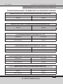
ТАБЛИЦА
СТАН-
ДАРТНАЯ
И БЫ-
СТРАЯ
КОНФОР-
КИ
ИНТЕН-
СИВ-
НОСТЬ
НАГРЕВА
ВОЗМОЖНОЕ ПРИМЕНЕНИЕ
0 Откл
1 Слабая
Растапливание сливочно-
го масла, шоколада и т.д.
Нагревание небольшого
количества жидкости.
2 Низкая
Нагревание большого
количества жидкости.
Приготовление кремов
и соусов, требующих
длительной тепловой
обработки на малой
мощности.
3
Умерен-
ная
Размораживание про-
дуктов и приготовление
тушеных блюд, нагре-
вание до кипения или
медленное кипячение.
4 Средняя
Нагревание продуктов до
температуры кипения.
Подрумянивание мясных
и рыбных деликатесов.
5
Повы-
шенная
Приготовление эскало-
пов и стейков. Приготов-
ление больших объемов
продуктов при слабом
кипении.
6 Высокая
Нагревание больших
объемов жидкости до
кипения. Жарка.
рис. 4

18
ПАСПОРТ ТЕХНИЧЕСКОГО ИЗДЕЛИЯ РУССКИЙ
Комбинированные и газовые варочные поверхности
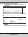
ПРЕДУПРЕЖДЕНИЯ:
Если варочная панель включается
в первый раз, или если она не исполь-
зовалась в течение длительного пе-
риода, ее следует высушить в течение
30 минут, установив переключатель в
положение № 1. Это позволит удалить
влагу, которая могла быть поглощена
изоляционными материалами.
При использовании прибора при-
держивайтесь следующих правил:
Сначала помещайте на конфорку
сковороду или кастрюлю и только за-
тем включайте конфорку.
Используйте только посуду, имею-
щую плоское и очень толстое дно (см.
рис. 5).
Не используйте посуду, размеры
которой меньше диаметра конфорки.
Перед помещением на конфорку
насухо вытирайте дно посуды.
Не оставляйте прибор без при-
смотра во время работы конфорок.
Следите за тем, чтобы к нему не при-
ближались дети. Следите также за тем,
чтобы ручки кастрюль и сковород на-
ходились в безопасном положении.
Проявляйте особую осторожность во
время приготовления блюд с исполь-
зованием растительных масел и жи-
ров, не допуская их воспламенения.
Конфорки остаются горячими в те-
чение длительного периода времени
даже после их отключения, поэтому
чтобы предотвратить ожоги, не при-
касайтесь к ним руками или другими
предметами.
При обнаружении на поверхности
варочной панели трещин немедленно
отключите прибор от электросети.
Перед тем как открыть крышку
(если она предусмотрена в данной
модели варочной панели), удалите с
ее поверхности все попавшие на нее
остатки пищи. Стеклянная крышка мо-
жет расколоться при нагревании пли-
ты. Поэтому, перед тем как ее закрыть,
следует отключить все конфорки.
ВАЖНО!
Перед выполнением чистки следу-
ет обязательно отключить прибор от
газовой и электрической сети.
рис. 5
ЧИСТКА
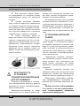
3) ГАЗОВАЯ ВАРОЧНАЯ
ПАНЕЛЬ
Варочную панель, эмалированные
стальные решетки, эмалированные
крышки конфорок С и рассекатели
конфорок M (см. рис. 6) необходи-
мо периодически промывать теплой
водой с мылом. Затем все части сле-
дует тщательно промыть и высушить.
Запрещается мыть еще не остывшую
панель, а также использовать абразив-
ные порошки.

19
РУССКИЙ ПАСПОРТ ТЕХНИЧЕСКОГО ИЗДЕЛИЯ
Комбинированные и газовые варочные поверхности
Не допускайте, чтобы на эмалиро-
ванных поверхностях прибора дли-
тельное время оставались остатки
уксуса, кофе, молока, соленой воды,
лимонного или томатного сока.
ПРЕДУПРЕЖДЕНИЯ:
При установке деталей на место
необходимо придерживаться приве-
денных ниже требований:
B Следите за тем, чтобы отвер-
стия рассекателей не были засорены.
B Следите за тем, чтобы эма-
лированные крышки конфорок С (рис.
6) правильно располагались на рассе-
кателях. Кроме того, они должны быть
устойчиво установлены.
B Решетка должна устанав-
ливаться таким образом, чтобы ее за-
кругленные углы были направлены к
боковому краю варочной панели.
B Если вращение крана за-
труднено, не пытайтесь прилагать к
нему чрезмерное усилие. В таком слу-
чае необходимо обратиться в центр
технической поддержки и обслужива-
ния для выполнения соответствующе-
го ремонта.
B Обеспечьте правильный
уход за варочной поверхностью, обра-
батывая ее после использования с по-
мощью специальных средств, прода-
ваемых в торговой сети. Это позволит
сохранить чистоту и безукоризненный
внешний вид варочной панели. Кроме
того, такой уход также позволит пре-
дотвратить образование ржавчины.
рис. 6
2) ЭЛЕКТРИЧЕСКАЯ ВАРОЧНАЯ
ПАНЕЛЬ
Для поддержания чистоты и без-
укоризненного внешнего вида вароч-
ной панели рекомендуется использо-
вать специальные средства для ухода
на силиконовой основе. Использова-
ние этих средств, например, до нача-
ла варки варенья, позволяет защитить
поверхность варочной панели.
Очень важно очищать поверхность
спустя некоторое время после каждо-
го использования, когда стекло еще
теплое.
Не используйте для этой цели ме-
таллические губки, абразивные по-
рошки или вызывающие коррозию
спреи.
В зависимости от степени загряз-
нения мы рекомендуем следующее:
 Незначительные пятна: для
чистки достаточно использовать влаж-
ную чистую ткань.
 Нагар и загрязнения могут быть
удалены с помощью специального
скребка с лезвием (рис 7); чистку сле-
дует выполнять аккуратно, чтобы не
порезаться.

20
ПАСПОРТ ТЕХНИЧЕСКОГО ИЗДЕЛИЯ РУССКИЙ
Комбинированные и газовые варочные поверхности
 Для удаления следов жидко-
сти, вылившейся из кастрюли, может
использоваться уксус или лимонная
кислота.
 Особое внимание уделяйте
тому, чтобы на варочную поверхность
не попадал сахар или сахаросодержа-
щие продукты. При попадании этих ве-
ществ на варочную панель отключите
ее и очистите поверхность с помощью
горячей воды и скребка с лезвием.
 Спустя некоторое время на
варочной панели могут появиться по-
тертости и царапины (рис. 8) из-за не-
правильного выполнения чистки и не-
правильного использования посуды.
Царапины очень сложно поддаются
удалению, но их наличие совсем не
влияет на рабочие характеристики ва-
рочной панели.
рис. 7 рис. 8
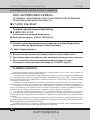
БЕЗОПАСНОСТЬ
УСТАНОВКИ
ТЕХНИЧЕСКАЯ ИНФОРМАЦИЯ
ДЛЯ УСТАНОВЩИКА
Установка, регулировка и техниче-
ское обслуживание прибора должны
проводиться только квалифицирован-
ными инженерами.
Компания-изготовитель не несет
ответственность за ущерб людям, жи-
вотным или имуществу, который мо-
жет быть нанесен вследствие непра-
вильной установки прибора.
На протяжении всего срока службы
системы внесение изменений в кон-
струкцию автоматических защитных и
регулирующих устройств допускается
только специалистами компании-из-
готовителя или ее официального ди-
лера.
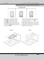
4) УСТАНОВКА ВАРОЧНОЙ
ПАНЕЛИ
После снятия внешней упаковки, а
также пленки с поставляемых отдель-
но деталей проверьте состояние при-
бора. В случае возникновения каких-
либо сомнений в работоспособности
прибора не используйте его и обрати-
тесь за помощью к квалифицирован-
ным специалистам.
Запрещается оставлять упаковоч-
ные материалы (картон, пакеты, пено-
пласт, гвозди и т.д.) в доступных для
детей местах, поскольку это может
приводить к возникновению опасных
ситуаций.
Размеры отверстия, которое не-
обходимо выполнить в верхней части
модульного шкафа для встраивания
варочной панели, приведены на рис. 9.
Обязательно соблюдайте требова-
ния, предъявляемые к размерам от-
верстия для установки варочной па-
нели.
Прибор относится к оборудованию
3-го класса, и на него распространя-
ются соответствующие положения
нормативных документов.
Страница загружается ...
Страница загружается ...
Страница загружается ...
Страница загружается ...
Страница загружается ...
Страница загружается ...
Страница загружается ...
Страница загружается ...
Страница загружается ...
Страница загружается ...
Страница загружается ...
Страница загружается ...
-
 1
1
-
 2
2
-
 3
3
-
 4
4
-
 5
5
-
 6
6
-
 7
7
-
 8
8
-
 9
9
-
 10
10
-
 11
11
-
 12
12
-
 13
13
-
 14
14
-
 15
15
-
 16
16
-
 17
17
-
 18
18
-
 19
19
-
 20
20
-
 21
21
-
 22
22
-
 23
23
-
 24
24
-
 25
25
-
 26
26
-
 27
27
-
 28
28
-
 29
29
-
 30
30
-
 31
31
-
 32
32


Kuppersberg FV3XE Руководство пользователя
- Категория
- Кухонные плиты (варочные панели)
- Тип
- Руководство пользователя
Задайте вопрос, и я найду ответ в документе
Поиск информации в документе стал проще с помощью ИИ
на других языках
- English: Kuppersberg FV3XE User manual