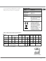
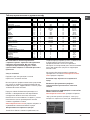
Indesit C 34S G3 (W)UA/HA S Руководство пользователя
- Категория
- Аксессуары для кухни и посуды
- Тип
- Руководство пользователя

English
Русский
Украінська
GB
RS
UA
Operating Instructions
COOKER AND OVEN
Contents
Operating Instructions,1
Warnings,2
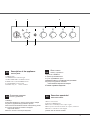
Description of the appliance-Overall view,4
Description of the appliance-Control Panel,5
Installation,6
Start-up and use,10
Precautions and tips,13
Care and maintenance,14
Assistance,14
Руководство по эксплуатации
КУХОННАЯ ПЛИТА С ДУХОВЫМ ШКАФОМ
Содержание
Руководство по эксплуатации,1
Warnings,2
Описание изделия-Общий вид,4
Описание изделия-Панель управления,5
Монтаж,15
Включение и эксплуатация,19
Предосторожности и рекомендации,22
Техническое обслуживание и уход,23
Техническое обслуживание,23
Інструкціі з експлуатаціі
КУХНЯ
Зміст
Інструкціі з експлуатаціі,1
ЗАПОБІЖНИХ ЗАХОДІВ,2
Опис установки-Загальнии вигляд,4
Опис установки-Панель управління,5
Встановлення,24
Включення і використання,28
Запобіжні засоби і поради,31
Догляд i технічне обслуговування,32
Допомога,32
C 34S G3 UA /HA S
RO
Românã
Instrucюiuni de folosire
ARAGAZ ЄI CUPTOR
Sumar
Instrucюiuni de folosire,1
AVERTISMENT,2
Descrierea aparatului- Vedere de ansamblu,4
Descrierea aparatului-Panoul de control,5
Instalare,33
Pornire єi utilizare, 37
Precauюii єi sfaturi,40
Оntreюinere єi curгюire,41
Asistenюг,41

2
GB
RS
Warnings
WARNING: The appliance and its
accessible parts become hot during
use.
Care should be taken to avoid
touching heating elements.
Children less than 8 years of
age shall be kept away unless
continuously supervised.
This appliance can be used by
children aged from 8 years and
above and persons with reduced
physical, sensory or mental
capabilities or lack of experience and
knowledge if they have been given
supervision or instruction concerning
use of the appliance in a safe
way and understand the hazards
involved. Children shall not play with
the appliance. Cleaning and user
maintenance shall not be made by
children without supervision.
WARNING: Unattended cooking on a
hob with fat or oil can be dangerous
and may result in fire.
NEVER try to extinguish a fire with
water, but switch off the appliance
and then cover flame e.g. with a lid
or a fire blanket.
Do not use harsh abrasive cleaners
or sharp metal scrapers to clean
the oven door glass since they can
scratch the surface, which may result
in shattering of the glass.
The internal surfaces of the
compartment (where present) may
become hot.
Never use steam cleaners or
pressure cleaners on the appliance.
Remove any liquid from the lid before
opening it.
Do not close the glass cover (if
present) when the gas burners or
electric hotplates are still hot.
WARNING: Ensure that the appliance
is switched off before replacing
the lamp to avoid the possibility of
electric shock.
ВНИМАНИЕ: Данное изделие и
его доступные комплектующие
сильно нагреваются в процессе
эксплуатации.
Будьте осторожны и не касайтесь
нагревательных элементов.
Не разрешайте детям младше 8
лет приближаться к изделию без
контроля.
Данное изделие может быть
использовано детьми старше 8
лет и лицами с ограниченными
физическими, сенсорными или
умственными способностями или
без опыта и знания
о правилах
использования изделия при условии
надлежащего контроля или обучения
безопасному использованию изделия
с учетом соответствующих рисков. Не
разрешайте детям играть с изделием.
Не разрешайте детям осуществлять
чистку и уход за изделием без
контроля взрослых.
ВНИМАНИЕ: Опасно оставлять
включенную конфорку с маслом или
жиром без присмотра, так как это
может
привести к пожару.
НИКОГДА не пытайтесь погасить
пламя/пожар водой. Прежде всего
выключите изделие и накройте пламя
крышкой или огнеупорной тканью.
ВНИМАНИЕ: Опасность пожара: не
оставляйте предметов на варочных
поверхностях.
ВНИМАНИЕ: Если
стеклокерамическая поверхность
варочной панели треснула,
выключите ее во избежание ударов
током.
Не используйте абразивные
вещества или режущие
металлические скребки
для чистки
стеклянной дверцы духового шкафа,
так как они могут поцарапать
поверхность, что может привести к
разбиванию стекла.
Внутренняя поверхность ящика (если
он имеется) может сильно нагреться.
Никогда не используйте паровые
чистящие агрегаты или агрегаты
под высоким давлением для чистки
изделия.
Если на крышку пролита жидкость,
удалите ее перед тем,
как открыть
крышку. Не закрывайте стеклянную
крышку варочной панели (если
она имеется), если газовые или
электрические конфорки еще
горячие.
ВНИМАНИЕ: Проверьте, чтобы
изделие было выключено, перед
заменой лампочки во избежание
возможных ударов током.
ПРЕДУПРЕЖДЕНИЯ

GB
3
UA
RO
УВАГА! Під час роботи цей
прилад, а також його доступні
частини нагріваються до високих
температур.
Слід бути особливо обережними,
щоб не торкатися нагрівальних
елементів.
Діти віком до 8 років мають
знаходитися на небезпечній відстані
від приладу, якщо неможливо
забезпечити постійний контроль над
ними.
Дозволяється користування цим
приладом дітьми віком від 8 років,
а
також особами з обмеженими
фізичними, сенсорними або
розумовими можливостями або
особами без належного досвіду
і знань, якщо вони перебувають
під постійним контролем або
проінструктовані щодо правил з
небезпечного користування приладу
і усвідомлюють ступені ризику.
Не дозволяйте дітям гратися з
приладом. Операції з очищення і
догляду не повинні виконуватися
дітьми без
належного контролю.
УВАГА! Небезпечно залишати без
нагляду плити з жиром або олією,
тому що це може призвести до
пожежі.
НІ В ЯКОМУ РАЗІ не слід
намагатися погасити полум’я/
пожежу водою. Необхідно
вимкнути прилад і накрити
полум’я, наприклад, кришкою або
вогнетривким покривалом.
Не використовувати абразивні
засоби ані металеві загострені
шпателі
для очищення скляних
дверцях духовки, тому що вони
можуть пошкрябати поверхню,
призводячи до розтріскування скла.
Внутрішні поверхні відділення (де
вони наявні) можуть нагріватися до
високих температур.
Забороняється використання
апаратів для очищення парою або
високим тиском.
Витріть насухо всі наявні на
кришці рідини, перш ніж відкрити
її. Не закривайте скляну кришку
(якщо вона наявна), якщо газові
пальники або електричні конфорки
залишаються нагрітими.
УВАГА! Щоб запобігти
враженню електричним струмом
переконайтеся в тому, що прилад
вимкнений, перш ніж заміняти
лампочку.
УВАГА! використання невідповідних
захисних пристроїв варильної
поверхні може призвести до
нещасних випадків.
ЗАПОБІЖНИХ ЗАХОДІВ
ATENŢIE: Acest aparat şi părţile sale
accesibile devin foarte calde în timpul
folosirii.
Trebuie să fi ţi atenţi şi să nu atingeţi
elementele de încălzire.
Îndepărtaţi copiii sub 8 ani dacă nu
sunt supravegheaţi continuu.
Acest aparat poate fi utilizat de
copiii de peste 8 ani şi de persoane
cu capacităţi fi zice, senzoriale sau
mentale reduse sau fără experienţă
şi cunoştinţe dacă se afl ă sub o su-
praveghere corespunzătoare sau
dacă au fost instruiţi cu privire la folo-
sirea aparatului în mod sigur şi dacă
îşi dau seama de pericolele core-
late. Copiii nu trebuie să se joace cu
aparatul. Operaţiunile de curăţare şi
de întreţinere nu trebuie să fi e efectu-
ate de copii f
ără supraveghere.
ATENŢIE: Lăsarea unui aragaz nesu-
pravegheat cu grăsimi şi uleiuri poate
fi periculoasă şi poate provoca un
incendiu.
Nu trebuie NICIODATĂ să încercaţi
să stingeţi o fl acără/incendiu cu apă,
ci trebuie să stingeţi aparatul şi să
acoperiţi fl acăra, de exemplu cu un
capac sau cu o pătură ignifugă.
Nu folosiţi produse abrazive, nici perii
de metal tăioase pentru a curăţa uşa
de sticlă a cuptorului, deoarece ar
putea zgâria suprafaţa, provocând
astfel spargerea geamului.
Suprafeţele interne ale sertarului
(dacă este prezent) se pot încălzi.
Nu folosiţi niciodată aparate cu aburi
sau sub presiune pentru a curăţa
aparatul.
Eliminaţi eventualele reziduuri de
lichid de pe capac, înainte de a-l de-
schide. Nu închideţi capacul din sticl
ă
(dacă este prezent) cu arzătoarele de
gaz sau plita electrică încă calde.
ATENŢIE: Asiguraţi-vă că aparatul
este stins înainte de a înlocui
lampa pentru a evita posibilitatea
electrocutărilor.
ATENŢIE: folosirea unor protecţii
necorespunzătoare ale plitei poate
provoca accidente.
AVERTISMENT

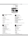
4
1 Hob burner
2 Hob Grid
3.Control panel
4.Sliding grill rack
5.DRIPPING pan
6.Adjustable foot
7.Containment surface for spills
8.GUIDE RAILS for the sliding racks
9.position 5
10.position 4
11.position 3
12.position 2
13.position 1
14. Glass Cover *(Available only on certain
models)
Description of the appliance
Overall view
GB
1 Газовые горелки
2 Рабочая поверхность
3 Панель управления
4 Решетка духовки
5 Противень или жарочный лист
6 Регулируемые ножки
7 Электрические конфорки
8
HAПPABЛЯЮЩИE для противеней решеток
9 Положение 1
10 Положение 2
11 Положение 3
12 Положение 4
13 Положение 5
14 Cтеклянная крышка
(Имеется только в некоторых моделях.)
Описание изделия
Общий вид
UA
Опис плити
Загальнии вигляд
1. Газовий пальник
2. Піддон на випадок переливань
3.Панель управління
4.Полка РЕШІТKИ
5.Полка ДEКО
6.Лапка для налаштування
7.Пoверхня для збирання збiглoї piдини
8.HAПPABЛЯЮЧІ для полиць
9.положення 5
10.положення 4
11.положення 3
12.положення 2
13.положення 1
14.Скляна кришка (Є лише в деяких моделях.)
RS
1.Arzătoare pe gaz
2.Grătare plită
3.Panou frontal de control
4.Grătarul cuptorului
5.Tavă de coacere
6.Picioare reglabile
7.Plită
8.GHIDAJE alunecare rafturi
9.nivelul 5
10. nivelul 5
11.nivelul 5
12.nivelul 5
13.nivelul 5
14.Capacul din sticlă
(prezent doar la anumite modele)
Descriere aparatului
Vedere de ansamblu
RO
1
2
3
4
5
6
7
8
9
10
11
12
13
6
14

GB
5
Description of the appliance
Control panel
GB
1.TIMER knob*
2.THERMOSTAT indicator light
3.OVEN AND GRILL CONTROL knob
4.OVEN LIGHT / ROTISSERIE button
5. Hob BURNER control knob
*Available only on certain models
Описание изделия
Панель управления
UA
Опис плити
Панель управління
RS
1.Таймер*
2.Световой индикатор термостата духового шкафа
3.Рукоятка управления духовкой и грилем
4.Кнопка включения/выключения освещения духовки
5. Рукоятки включения газовых конфорок
варочной панели
*Имеется только в некоторых моделях
1.Сукоятка ТАЙМЕРА*
2. Індикатор TEPMOCTATУ
3. Ручка ДУХОВКА й гриля
4.КНОПКА РОЖНА та ОСВІТЛЕННЯ ДУХОВКИ
5.Ручки для керування газовими
пальниками на варильній поверхні
*
Є лише в деяких моделях
Descriere aparatului
Panoul de control
RO
1.Buton cronometru*
2.Indicator TERMOSTAT
3.Buton de comandã pentru cuptor ºi grill
4.Buton pentru activarea luminii din cuptor/ rotisserie
5.Butoane comandi ochiuri aragaz
*prezent doar la anumite modele
3
4
2
5
1
5

6
GB
! Before operating your new appliance please read
this instruction booklet carefully. It contains
important information concerning the safe installation
and operation of the appliance.
! Please keep these operating instructions for future
reference. Make sure that the instructions are kept
with the appliance if it is sold, given away or moved.
! The appliance must be installed by a qualified
professional according to the instructions provided.
! Any necessary adjustment or maintenance must be
performed after the cooker has been disconnected
from the electricity supply.
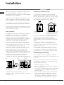
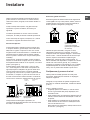
Room ventilation
The appliance may only be installed in permanently-
ventilated rooms, according to current national
legislation. The room in which the appliance is
installed must be ventilated adequately so as to
provide as much air as is needed by the normal gas
combustion process (the flow of air must not be
lower than 2 m
3
/h per kW of installed power).
The air inlets, protected by grilles, should have a
duct with an inner cross section of at least 100 cm
2
and should be positioned so that they are not liable
to even partial obstruction (
see figure A
).
These inlets should be enlarged by 100% - with a
minimum of 200 cm
2
- whenever the surface of the
hob is not equipped with a flame failure safety
device. When the flow of air is provided in an
indirect manner from adjacent rooms (
see figure B
),
provided that these are not communal parts of a
building, areas with increased fire hazards or
bedrooms, the inlets should be fitted with a
ventilation duct leading outside as described above.
AB
! After prolonged use of the appliance, it is
advisable to open a window or increase the speed of
any fans used.
Disposing of combustion fumes
The disposal of combustion fumes should be
guaranteed using a hood connected to a safe and
efficient natural suction chimney, or using an electric
fan that begins to operate automatically every time
the appliance is switched on (
see figure
).
! The liquefied petroleum gases are heavier than air
and collect by the floor, therefore all rooms
containing LPG cylinders must have openings
leading outside so that any leaked gas can escape
easily.
LPG cylinders, therefore, whether partially or
completely full, must not be installed or stored in
rooms or storage areas that are below ground level
(cellars, etc.). Only the
cylinder being used should be stored in the room;
this should also be kept well away from sources
of heat (ovens, chimneys, stoves) that may cause
the temperature of the cylinder to rise above 50°C.
Positioning and levelling
! It is possible to install the appliance alongside
cupboards whose height does not exceed that of the
hob surface.
! Make sure that the wall in contact with the back of
the appliance is made from a non-flammable, heat-
resistant material (T 90°C).
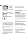
To install the appliance correctly:
• Place it in the kitchen, dining room or the bed-sit
(not in the bathroom).
• If the top of the hob is higher than the cupboards,
the appliance must be installed at least 200 mm
away from them.
• If the cooker is installed underneath a wall cabinet,
there must be a minimum distance of 420 mm
between this cabinet and the top of the hob.
This distance should be increased to 700 mm if
the wall cabinets are flammable (
see figure
).
A
Fumes channelled through
a chimney or branched
flue system reserved for
cooking appliances)
Installation
Adjacent room Room requiring
ventilation
Ventilation opening for
comburent air
Increase in the gap between
the door and the flooring
Fumes channelled
straight outside

7
GB
• Do not position
blinds behind the
cooker or less than 200
mm away from its
sides.
• Any hoods must be
installed according to
the instructions listed in
the relevant operating
manual.
Levelling
If it is necessary to level the
appliance, screw the
adjustable feet into the places
provided on each corner of the
base of the cooker (
see
figure
).
The legs* fit into the slots on
the underside of the base of
the cooker.
Electrical connection
Install a standardised plug corresponding to the
load indicated on the appliance data plate (
see
Technical data table
).
The appliance must be directly connected to the mains
using an omnipolar circuit-breaker with a minimum
contact opening of 3 mm installed between the
appliance and the mains. The circuit-breaker must be
suitable for the charge indicated and must comply with
NFC 15-100 regulations (the earthing wire must not be
interrupted by the circuit-breaker). The supply cable
must be positioned so that it does not come into
contact with temperatures higher than 50°C at any point.
Before connecting the appliance to the power
supply, make sure that:
• The appliance is earthed and the plug is compliant
with the law.
• The socket can withstand the maximum power of
the appliance, which is indicated by the data plate.
• The voltage is in the range between the values
indicated on the data plate.
• The socket is compatible with the plug of the
appliance. If the socket is incompatible with the
plug, ask an authorised technician to replace it.
Do not use extension cords or multiple sockets.
HOOD
420
Min.
min.
650
mm. with hood
min.
700
mm. without hood
mm.
600
Min. mm.
420
Min. mm.
* Only available in certain models
! Once the appliance has been installed, the power
supply cable and the electrical socket must be
easily accessible.
! The cable must not be bent or compressed.
! The cable must be checked regularly and replaced
by authorised technicians only.
! The manufacturer declines any liability should
these safety measures not be observed.
Gas connection
Connection to the gas network or to the gas cylinder
may be carried out using a flexible rubber or steel
hose, in accordance with current national legislation
and after making sure that the appliance is suited to
the type of gas with which it will be supplied (see the
rating sticker on the cover: if this is not the case
see
below
). When using liquid gas from a cylinder, install a
pressure regulator which complies with current national
regulations. To make connection easier, the gas
supply may be turned sideways*: reverse the position
of the hose holder with that of the cap and replace the
gasket that is supplied with the appliance.
! Check that the pressure of the gas supply is
consistent with the values indicated in the Table of
burner and nozzle specifications (
see below
). This
will ensure the safe operation and durability of your
appliance while maintaining efficient energy
consumption.
Gas connection using a flexible rubber hose
Make sure that the hose complies with current
national legislation. The internal diameter of the hose
must measure: 8 mm for liquid gas supply; 13 mm
for methane gas supply.
Once the connection has been performed, make
sure that the hose:
• Does not come into contact with any parts that
reach temperatures of over 50°C.
• Is not subject to any pulling or twisting forces and
that it is not kinked or bent.
• Does not come into contact with blades, sharp
corners or moving parts and that it is not
compressed.
• Is easy to inspect along its whole length so that
its condition may be checked.
• Is shorter than 1500 mm.
• Fits firmly into place at both ends, where it will be
fixed using clamps that comply with current
regulations.

8
GB
A
V
! If one or more of these conditions is not fulfilled or
if the cooker must be installed according to the
conditions listed for class 2 - subclass 1 appliances
(installed between two cupboards), the flexible steel
hose must be used instead (
see below
).
Connecting a flexible jointless stainless steel pipe
to a threaded attachment
Make sure that the hose and gaskets comply with
current national legislation.
To begin using the hose, remove the hose holder on the
appliance (the gas supply inlet on the appliance is a
cylindrical threaded 1/2 gas male attachment).
! Perform the connection in such a way that the hose
length does not exceed a maximum of 2 metres,
making sure that the hose is not compressed and
does not come into contact with moving parts.
Checking the connection for leaks
When the installation process is complete, check
the hose fittings for leaks using a soapy solution.
Never use a flame.
Adapting to different types of gas
It is possible to adapt the appliance to a type of gas
other than the default type (this is indicated on the
rating label on the cover).
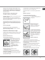
Adapting the hob
Replacing the nozzles for the hob burners:
1. Remove the hob grids and slide the burners off
their seats.
2. Unscrew the nozzles using a
7 mm socket spanner (
see
figure
), and replace them with
nozzles suited to the new type
of gas(
see Burner and nozzle
specifications table
).
3. Replace all the components
by following the above
instructions in reverse.
Adjusting the hob burners’ minimum setting:
1. Turn the tap to the minimum position.
2. Remove the knob and adjust the regulatory
screw, which is positioned inside or next to the tap
pin, until the flame is small but steady.
! If the appliance is connected to a liquid gas
supply, the regulatory screw must be fastened as
tightly as possible.
3. While the burner is alight, quickly change the position
of the knob from minimum to maximum and vice versa
several times, checking that the flame is not
extinguished.
! The hob burners do not require primary air adjustment.
Adapting the oven
Replacing the oven burner nozzle:
1. Remove the oven compartment.
2. Slide out the protection
panel A
(
see diagram
).
3. Remove the oven burner
after unscrewing the screws V
(
see figure
).
The whole operation will be
made easier if the oven door
is removed.
4. Unscrew the nozzle using a
special nozzle socket spanner
(
see figure
) or with a 7 mm
socket spanner, and replace it
with a new nozzle that is
suited to the new type of gas
(
see Burner and nozzle
specifications table
).
Adjusting the gas oven burner’s minimum setting:
1. Light the burner (
see Start-up and Use
).
2. Turn the knob to the minimum position (MIN) after
it has been in the maximum position (MAX) for
approximately 10 minutes.
3. Remove the knob.
4. Tighten or loosen the adjustment screws on the
outside of the thermostat pin (
see figure
) until the
flame is small but steady.
! If the appliance is connected to liquid gas, the
adjustment screw must be fastened as tightly as
possible.

9
GB
C 34S G3 UA /HA S
5. Turn the knob from the MAX position to the MIN
position quickly or open and shut the oven door,
making sure that the burner is not extinguished.
S
S
R
A
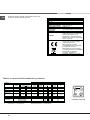
TECHNICAL DATA
Oven dimensions
(HxWxD)
34x38x44 cm
Volume 57 l
Useful
measurements
relating to the oven
compartment
width 42 cm
depth 44 cm
height 17 cm
Power supply voltage
and frequency
see data plate
Burners
may be adapted for use with any
type of gas shown on the data
plate, which is located inside the
flap or, after the oven
compartment has been opened,
on the left-hand wall inside the
oven.
EC Directives: 2006/95/EC dated
12/12/06 (Low Voltage) and
subsequent amendments -
2004/108/EC dated 15/12/04
(Electromagnetic Compatibility)
and subsequent amendments -
2009/142/EC dated 30/11/09
(Gas) and subsequent
amendments - 93/68/EEC dated
22/07/93 and subsequent
amendments - 2002/96/EC.
1275/2008 (Stand-by/ Off mode)
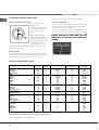
Table 1 Liquid Gas Natural Gas
Burner Diameter
(mm)
Thermal Power
kW (p.c.s.*)
By Pass
1/100
Nozzle
1/100
Flow*
g/h
Nozzle
1/100
Flow*
l/h
Nozzle
1/100
Flow*
l/h
Nominal Reduced (mm) (mm) *** ** (mm) (mm)
Fast
(Large)(R)
100 3.00 0.7 41 87 218 214 128 286 143 286
Semi Fast
(Medium)(S)
75 1.90 0.4 30 70 138 136 104 181 118 181
Auxiliary
(Small)(A)
51 1.00 0.4 30 52 73 71 76 95 80 95
Oven - 2.80 1.0 46 80 204 200 119 267 132 257
Supply
Pressures
Nominal (mbar)
Minimum (mbar)
Maximum (mbar)
28-30
20
35
37
25
45
20
17
25
13
6,5
18
* At 15°C 1013 mbar-dry gas *** Butane P.C.S. = 49,47 MJ/Kg
** Propane P.C.S. = 50,37 MJ/Kg Natural P.C.S. = 37,78 MJ/m³
Table of burner and nozzle specifications

10
GB
Using the hob
Lighting the burners
For each BURNER knob there is a complete ring
showing the strength of the flame for the relevant
burner.
To light one of the burners on the hob:
1. Bring a flame or gas lighter close to the burner.
2. Press the BURNER knob and turn it in an
anticlockwise direction so that it is pointing to the
maximum flame setting .
3. Adjust the intensity of the flame to the desired
level by turning the BURNER knob in an
anticlockwise direction. This may be the minimum
setting , the maximum setting or any position
in between the two.
If the appliance is fitted with
an electronic lighting
device* (
see figure
), press
the ignition button, marked
with the symbol
, then
hold the BURNER knob
down and turn it in an
anticlockwise direction, towards the maximum flame
setting, until the burner is lit.
Several models are equipped with an ignition device
which is built into the knob; in this case the
electronic ignition device* is present (
C
) but the
ignition button is not. Simply press the BURNER
knob and turn it in an anticlockwise direction so that
it is pointing to the maximum flame setting, until the
burner is lit. The burner may be extinguished when
the knob is released. If this occurs, repeat the
operation, holding the knob down for a longer period
of time.
! If the flame is accidentally extinguished, switch off
the burner and wait for at least 1 minute before
attempting to relight it.
If the appliance is equipped with a flame failure
safety device*(X), press and hold the BURNER knob
for approximately 2-3 seconds to keep the flame
alight and to activate the device.
To switch the burner off, turn the knob until it
reaches the stop position •.
Start-up and use
Practical advice on using the burners
For the burners to work in the most efficient way
possible and to save on the amount of gas
consumed, it is recommended that only pans that
have a lid and a flat base are used. They should also
be suited to the size of the burner.
To identify the type of burner, please refer to the
diagrams contained in the “Burner and nozzle
specifications”.
Using the oven
! The first time you use your appliance, heat the
empty oven with its door closed at its maximum
temperature for at least half an hour. Ensure that the
room is well ventilated before switching the oven off
and opening the oven door. The appliance may emit a
slightly unpleasant odour caused by protective
substances used during the manufacturing process
burning away.
! Before operating the product, remove all plastic film
from the sides of the appliance.
! Never put objects directly on the bottom of the
oven; this will avoid the enamel coating being
damaged. Only use position 1 in the oven when
cooking with the rotisserie spit.
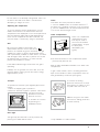
Lighting the oven
To light the oven burner, bring
a flame or gas lighter close to
opening F (
see figure
) and
press the OVEN control knob
while turning it in an
anticlockwise direction until it
reaches the MAX position.
If, after 15 seconds, the burner is still not alight,
release the knob, open the oven door and wait for at
least 1 minute before trying to light it again.
! The oven is fitted with a safety device and it is
therefore necessary to hold the OVEN control knob
down for approximately 6 seconds.
F
*
Only available in certain models.
Burner ř Cookware diameter (cm)
Fast (R) 24 - 26
Semi Fast (S) 16 - 20
Auxiliary (A) 10 - 14
X
C
WARNING! The glass lid canWARNING! The glass lid can
WARNING! The glass lid canWARNING! The glass lid can
WARNING! The glass lid can
break in if it is heated up. Turnbreak in if it is heated up. Turn
break in if it is heated up. Turnbreak in if it is heated up. Turn
break in if it is heated up. Turn
off all the burners and theoff all the burners and the
off all the burners and theoff all the burners and the
off all the burners and the
electric plates before closingelectric plates before closing
electric plates before closingelectric plates before closing
electric plates before closing
the lid. *Applies to the modelsthe lid. *Applies to the models
the lid. *Applies to the modelsthe lid. *Applies to the models
the lid. *Applies to the models
with glass cover only.with glass cover only.
with glass cover only.with glass cover only.
with glass cover only.

11
GB
* Only available in certain models.
A
S
! If the flame is accidentally extinguished, switch off
the burner and wait for at least 1 minute before
attempting to relight the oven.
Adjusting the temperature
To set the desired cooking temperature, turn the
OVEN control knob in an anticlockwise direction.
Temperatures are displayed on the control panel and
may vary between MIN (140°C) and MAX (250°C).
Once the set temperature has been reached, the
oven will keep it constant by using its thermostat.
Grill
By turning the OVEN control knob in an
anticlockwise direction until it reaches the
position, the infrared ray grill is activated. The grill
enables the surface of food to be browned evenly
and is particularly suitable for roast dishes, schnitzel
and sausages. Place the rack in position 4 or 5 and
the dripping pan in position 1 to collect fat and
prevent the formation of smoke.
! The GRILL indicator light shows when the grill is
operating.
! Always use the grill with the oven door shut; this
achieves better cooking results and saves energy
(approximately 10%).
Turnspit
To operate the rotisserie (
see diagram
) proceed as
follows:
1. Place the dripping pan in position 1.
2. Place the rotisserie support in position 4 and insert
the spit in the hole
provided on the back
panel of the oven.
3. Acitvate the function
by pressing the
TURNSPIT button.
Oven light
The light may be switched on at any moment by
pressing the OVEN LIGHT button.
Timer*
To activate the Timer proceed as follows:
1. Turn the TIMER knob in a clockwise direction
for almost one complete revolution to set the buzzer.
2. Turn the TIMER knob in an anticlockwise direction
to set the desired length of time.
Lower compartment*
There is a compartment
underneath the oven
that may be used to
store oven accessories
or deep dishes. To open
the door pull it
downwards (
see
figure
).
! The internal surfaces of the compartment (where
present) may become hot.
! Do not place flammable materials in the lower oven
compartment.
In gas cooker models, there is a sliding protection
layer A that shields the lower compartment from the
heat generated by the burner (
see figure
).
To remove the sliding
protection remove the screw S
(
see figure
). To replace it, lock
it in place with the screw S.
! Before using the oven make
sure that the sliding protection
is fixed correctly.

12
GB
Oven cooking advice table
Foods Weight (in
k
g)
Rack
p
os i ti o n
Preheating time (min) Recommended
Tem
p
erature
(
°C
)
Cook ing time
(
mi nutes
)
Pasta
Lasagne
Cannelloni
Gratin dishes
2.5
2.5
2.5
2
2
2
200-210
200
200
10
10
10
75-85
50-60
50
-
60
Meat
Veal
Chicken
Duck
Rabbit
Pork
Lamb
1.5
1.5
1.8
2.0
2.1
1.8
3
3
3
3
3
3
200-210
210-220
200
200
200
200
10
10
10
10
10
10
95-100
90-100
100-110
70-80
70-80
100-105
Fish
Mackerel
Dentex
Trout baked in foil
1.1
1.5
1.0
3
3
3
180-200
180-200
180-200
10
10
10
45-50
45-55
45
-
50
Pizza
Neapolitan-style
1.0
4
210-220
15
20-25
Pies
Biscuits
Tart
Savoury pies
Leavened cakes
0.5
1.1
1.0
1.0
4
4
4
4
180
180
180
170
15
15
15
15
25-35
40-45
50-55
40-45
Grilled foods
Veal steak
Cutlets
Hamburgers
Mackerel
Toast
1
1.5
1
1
4 шт.
4
4
3
4
4
5
5
5
5
5
-
-
-
-
-
15-20
20
20-30
15-20
4-5
NB: cooking times are approximate and may vary according to personal taste. When cooking using the grill, the dripping
pan must always be placed on the 1st oven rack from the bottom.
* Only available in certain models.
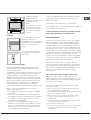
Clock with Country Style timer *
How to reset the correct time
The oven must be
plugged in.
Pull the knob and turn
it anticlockwise until
you set the correct
time.
! !
! !
! The programmer is
electrically powered,
therefore in the event of
a power shortage, it will
stop working for the
entire duration of the
same. Following this power failure, the correct time
will have to be reset.
Timer Feature
The timer feature allows you to enter a given amount
of time from which the timer begins to count down.
This feature does not turn the oven on or off; it
merely sounds when the time has elapsed.
How to set the timer
Turn the knob anticlockwise until the marker lines
up with the desired time (internal scale), which
can be seen in the “window”.
The time countdown will begin immediately.
To interrupt the timer buzzer, or to use only the
clock feature, set the marker to the symbol
!!
!!
!
When inserting the shelf make sure theWhen inserting the shelf make sure the
When inserting the shelf make sure theWhen inserting the shelf make sure the
When inserting the shelf make sure the
backstop is at the rear of the cavity (seebackstop is at the rear of the cavity (see
backstop is at the rear of the cavity (seebackstop is at the rear of the cavity (see
backstop is at the rear of the cavity (see
image).image).
image).image).
image).

13
GB
Precautions and tips
! This appliance has been designed and manufactured in
compliance with international safety standards.
The following warnings are provided for safety reasons and
must be read carefully.
General safety
• These instructions are only valid for the
countries whose symbols appear in the
manual and on the serial number plate.•
The appliance was designed for domestic use inside the
home and is not intended for commercial or industrial use.
• The appliance must not be installed outdoors, even in
covered areas. It is extremely dangerous to leave the
appliance exposed to rain and storms.
• Do not touch the appliance with bare feet or with wet or
damp hands and feet.
• The appliance must be used by adults only for
the preparation of food, in accordance with the
instructions outlined in this booklet. Any other
use of the appliance (e.g. for heating the room)
constitutes improper use and is dangerous.
The manufacturer may not be held liable for
any damage resulting from improper, incorrect
and unreasonable use of the appliance.
• The instruction booklet accompanies a class 1 (insulated)
or class 2 - subclass 1 (recessed between 2 cupboards)
appliance.
• Keep children away from the oven.
• Make sure that the power supply cables of other electrical
appliances do not come into contact with the hot parts of
the oven.
• The openings used for the ventilation and dispersion of
heat must never be covered.
• Do not close the glass hob cover (selected models only)
when the burners are alight or when they are still hot.
• Always use oven gloves when placing cookware in the
oven or when removing it.
• Do not use flammable liquids (alcohol, petrol, etc...) near
the appliance while it is in use.
• Do not place flammable material in the lower storage
compartment or in the oven itself. If the appliance is
switched on accidentally, it could catch fire.
• Always make sure the knobs are in the • position and that
the gas tap is closed when the appliance is not in use.
• When unplugging the appliance, always pull the plug from
the mains socket; do not pull on the cable.
• Never perform any cleaning or maintenance work without
having disconnected the appliance from the electricity
mains.
• If the appliance breaks down, under no circumstances
should you attempt to repair the appliance yourself.
Repairs carried out by inexperienced persons may cause
injury or further malfunctioning of the appliance. Contact
Assistance.
• Do not rest heavy objects on the open oven door.
• The appliance should not be operated by people
(including children) with reduced physical,
sensory or mental capacities, by inexperienced
individuals or by anyone who is not familiar with
the product. These individuals should, at the very
least, be supervised by someone who assumes
responsibility for their safety or receive
preliminary instructions relating to the operation of
the appliance.
• Do not let children play with the appliance.
Disposal
• When disposing of packaging material: observe local
legislation so that the packaging may be reused.
• The European Directive 2002/96/EC relating to Waste
Electrical and Electronic Equipment (WEEE) states that
household appliances should not be disposed of using the
normal solid urban waste cycle. Exhausted appliances
should be collected separately in order to optimise the cost
of re-using and recycling the materials inside the machine,
while preventing potential damage to the atmosphere and
to public health. The crossed-out dustbin is marked on all
products to remind the owner of their obligations regarding
separated waste collection.
Exhausted appliances may be collected by the public
waste collection service, taken to suitable collection areas
in the area or, if permitted by current national legislation,
they may be returned to the dealers as part of an
exchange deal for a new equivalent product.
All major manufacturers of household appliances
participate in the creation and organisation of systems for
the collection and disposal of old and disused appliances.
Respecting and conserving the
environment
• You can help to reduce the peak load of the electricity
supply network companies by using the oven in the hours
between late afternoon and the early hours of the morning.
• Check the door seals regularly and wipe them clean to
ensure they are free of debris so that they adhere properly
to the door, thus avoiding
heat dispersion.

14
GB
Care and maintenance
Switching the appliance off
Disconnect your appliance from the electricity supply
before carrying out any work on it.
Cleaning the appliance
! Do not use abrasive or corrosive detergents such as
stain removers, anti-rust products, powder detergents or
sponges with abrasive surfaces: these may scratch the
surface beyond repair.
! Never use steam cleaners or pressure cleaners on the
appliance.
• It is usually sufficient simply to wash the hob using a
damp sponge and dry it with absorbent kitchen roll.
• The stainless steel or enamel-coated external parts and
the rubber seals may be cleaned using a sponge that
has been soaked in lukewarm water and neutral soap.
Use specialised products for the removal of stubborn
stains. After cleaning, rinse well and dry thoroughly. Do
not use abrasive powders or corrosive substances.
• The hob grids, burner caps, flame spreader rings
and the hob burners can be removed
to make cleaning easier; wash them in hot water and
non-abrasive detergent, making sure all burnt-on
residue is removed before drying them thoroughly.
• For hobs with electronic ignition, the terminal part of the
electronic lighting devices should be cleaned
frequently and the gas outlet holes should be checked
for blockages.
• The inside of the oven should ideally be cleaned after
each use, while it is still lukewarm. Use hot water and
detergent, then rinse well and dry with a soft cloth. Do
not use abrasive products.
•
Clean the glass part of the oven door using a sponge
and a non-abrasive cleaning product, then dry
thoroughly with a soft cloth. Do not use rough abrasive
material or sharp metal scrapers as these could
scratch the surface and cause the glass to crack.
• The accessories can be washed like everyday
crockery, and are even dishwasher safe.
• Stainless steel can be marked by hard water that has
been left on the surface for a long time, or by
aggressive detergents containing phosphorus. After
cleaning, rinse well and dry thoroughly. Any remaining
drops of water should also be dried.
The cover
If the cooker is fitted with a
glass cover, this cover
should be cleaned using
lukewarm water. Do not use
abrasive products.
It is possible to remove the
cover in order to make
cleaning the area behind
the hob easier. Open the
cover fully and pull it
upwards (
see figure
).
! Do not close the cover when the burners are alight or
when they are still hot.
Inspecting the oven seals
Check the door seals around the oven periodically. If the
seals are damaged, please contact your nearest
Authorised After-sales Service Centre. We recommend
that the oven is not used until the seals have been
replaced.
Gas tap maintenance
Over time, the taps may become jammed or difficult to
turn. If this occurs, the tap must be replaced.
!
This procedure must be performed by a qualifiedThis procedure must be performed by a qualified
This procedure must be performed by a qualifiedThis procedure must be performed by a qualified
This procedure must be performed by a qualified
technician who has been authorised by thetechnician who has been authorised by the
technician who has been authorised by thetechnician who has been authorised by the
technician who has been authorised by the
manufacturer.manufacturer.
manufacturer.manufacturer.
manufacturer.
Replacing the oven light bulb
1. After disconnecting the oven
from the electricity mains, remove
the glass lid covering the lamp
socket (
see figure
).
2. Remove the light bulb and
replace it with a similar one:
voltage 230 V, wattage 25 W, cap
E 14.
3. Replace the lid and reconnect the oven to the electricity
supply.
! Do not use the oven lamp as/for ambient
lighting
Assistance
Please have the following information handy:
• The appliance model (Mod.).
• The serial number (S/N).
This information can be found on the data plate located on
the appliance and/or on the packaging.

15
RS
! Важно сохранить данное руководство для его
последующих консультации. В случае продажи,
передачи или переезда проверьте, чтобы данное
руководство сопровождало изделие.
! Внимательно прочитаите инструкции: в них
содержатся важные сведения об установке,
эксплуатации и безопасности изделия.
! Установка изделия производится в соответствии
с данными инструкциями квалифицированными
специалистами.
! Любая операция по
регуляции или техническому
обслуживанию должна производиться только
после отсоединения кухоннои плиты от сети
электропитания.
Вентиляция помещении
Изделие может быть установлено в помещениях
с постояннои вентиляциеи в соответствии с
деиствующими национальными нормативами. В
помещении, в котором устанавливается изделие,
должен быть обеспечен приток воздуха в объеме,
необходимом для оптимального горения газа (расход
воздуха
не должен быть меньше 2 м
3
/час на 1 кВт
установленнои мощности).
Вентиляционные отверстия, защищенные
решетками, должны иметь воздуховод площадью не
менее 100 мм
2
полезного сечения и распологаться
таким образом, чтобы их нельзя было закрыть, даже
частично (см. рисунок А).
Эти отверстия должны быть увеличины на 100% - то
есть иметь минимальную площадь 200 см
2
- если
варочная панель не оснащена предохранительным
устроиством отсутствия пламени и если воздух
в помещение поступает из смежных помещении
(см. рисунок В) – при условии, что это не общая
площадь здания, не пожароопасное помещение или
спальня - оснащенных воздуховодом, выходящим на
улицу, как описано выше.
! После продолжительного использования изделия
рекомендуется открыть
окно или включить более
интенсивныи режим вентиляторов.
Дымоудаление
Дымоудаление должно осуществляться через вытяжнои
зонт, соединенныи с эффективным дымоходом с
натуральнои тягои, или посредством электровентилятора,
которыи автоматически включается каждыи раз при
включении изделия (см. рисунок).
! Сжиженные натуральные газы тяжелее воздуха,
застиваются внизу, по этои причине помещения
для хранения баллонов с СНГ
должны иметь
внетиляционные отверстия у пола для вентиляции
возможных утечек газа.
Баллоны с СНГ, полные или частично
израсходованные, не дожны размещаться или
храниться в помещениях или хранилищах,
расположенных в подземных помещениях (подвалы,
и т.д.). Храните в помещении только рабочии баллон,
установив его вдали от источников тепла (духовок,
каминов, печеи), которые
могут нагреть его до
температуры выше 50°C.
Расположение и нивелировка
! Изделие может быть установлено рядом с
кухонными элементами, высота которых не
превышает поверхность варочнои панели.
! Проверьте, чтобы стена, к которои прилегает
задняя часть изделия, была из невозгораемого
материала и устоичивои к теплу (Т 90°C).
Порядок монтажа:
• изделие может быть установлено на кухне, в
столовои или в однокомнатнои квартире (не
в
ваннои комнате);
• если варочная панель кухоннои плиты выше
мебельных элементов, необходимо отодвинуть их
от плиты на расстояние не менее 200 мм.
• если кухонная плита устанавливается под
навесным шкафом, он должен располагаться на
высоте не менее 420 мм от поверхности варочнои
панели.
Это расстояние должно быть 700 мм, если
навесные шкафы выполнены
из возгораемого
материала (см. рисунок);
• не заправляите занавески за кухонную плиту и не
приближаите их на расстояние меньше 200 мм.
A
Дымоудаление через камин или
дымоход с медным покрытием
(для кухонных устроиств для
приготовления пищи)
Установка
Смежное
помещение
Вентилируемое
помещение
Вентиляционные
отверстия для притока
воздуха
Увеличение зазора между
дверью и полом
Прямое
дымоудаление в
атмосферу
A
B

16
RS
• возможная кухонная
вытяжка должна
быть установлена
в соответствии
с инструкциями,
приведенными
в техническом
руководстве к вытяжке.
Выравнивание
При необходимости
выровнять изделие вкрутите
в специальные отверстия по
углам в основании кухоннои
плиты прилагающиеся
регуляционные ножки (см.
рисунок).
Прилагающиеся ножки*
вставляются под основание
кухоннои плиты.
Электрическое подключение
Установите на кабель электропитания
нормализованную штепсельную вилку, расчитанную
на нагрузку, указанную на заводскои табличке
изделия (см. табличку с техническими данными).
В случае прямого подключения к сети электропитания
между кухоннои плитои и сетью необходимо установить
мультиполярныи выключатель с минимальным
расстоянием между контактами 3 мм, расчитанныи на
данную нагрузку и соответствующии нормативу NFC
15-100 (выключатель
не должен размыкать провод
заземления). Кабель электропитания должен быть
расположен таким образом, чтобы ни в однои точке его
температура не превышала температуру помещения
более чем на 50°C.
Перед подсоединением кабеля проверьте
следующее:
• электрическая розетка должна быть соединена с
заземлением и соответствовать нормативам;
• электрическая розетка должна быть рассчитана
на максимальную потребляемую мощность
изделия, указанную на заводскои таблике;
• напряжение и частота тока сети должны
соответствовать электрическим данным изделия;
• электрическая розетка должна быть совместима
со штепсельнои вилкои изделия. В противном
случае замените розетку или вилку; не
используите удлинители или троиники.
HOOD
420
Min.
min.
650
mm. with hood
min.
700
mm. without hood
mm.
600
Min. mm.
420
Min. mm.
*Имеется только в некоторых моделях
! Изделие должно быть установлено таким образом,
чтобы электрическии кабель и электророзетка были
легко доступны.
! Электрическии кабель изделия не должен быть
согнут или сжат.
! Регулярно проверяите состояние кабеля
электропитания и при необходимости поручаите его
замену только уполномоченным техникам.
! Фирма снимает с себя всякую
ответственность
в случае несоблюдения вышеописанных
правил.
Подсоединение к газопроводу
Подсоединение к газопроводу или к газовому
баллону выполняется посредством гибкого
резинового или стального шланга в соответствии с
деиствующими национальными нормативами, после
проверки настроики изделия на тип используемого
газа (см. этикетку настроики на крышке: в противном
случае см. ниже). В случае использования
сжиженного газа из баллона необходимо
установить регуляторы давления, соответствующие
деиствующему
национальному нормативу. Для
облегчения подсоединения газовыи патрубок
является ориентируемым*: поменяите местами
крепежную блокировочную гаику на заглушку и
замените прилагающееся уплотнение.
! Для надежного функционирования, рационального
использования энергии и более длительного срока
службы изделия проверьте, чтобы давление подачи
газа соответствовало значениям, указанным в
таблице «Характеристики газовых конфорок и
форсунок» (см. ниже).
Газовое подсоединение посредством резинового
шланга
Проверьте, чтобы шланг соответствовал
деиствующим национальным нормативам.
Внутреннии диаметр шланга должен быть: 8 мм для
сжижженного газа; 13 см для газа метана.
После подсоединения проверьте, чтобы шланг:
• не касался частеи, температура которых может
превысить 50°C;
• не был растянут, перекручен, сжат или заломлен;
• не касался режущих предметов, острых углов
,
подвижных предметов и не был сжат;
• был легко доступен для проверки по всеи длине;
• не был длиннее 1500 мм;
• был прочно закреплен с обоих концов при
помощи хомутов, соответствующих деиствующим
национальным нормативам.
! Если одно или несколько из вышеописанных
условии не будет соблюдено, и если кухонная плита

17
RS
A
V
устанавливается в условиях класса 2, подгруппа
1 (изделие, встроенное между двух мебельных
элементов), необходимо использовать гибкии
стальнои шланг (см. ниже).
Газовое подсоединение посредством шланга
из нержавеющеи стали со сплошнои оплеткои с
резьбовыми соединениями.
Проверьте, чтобы шланг и уплотнения
соответствовали деиствующим национальным
нормативам.
Для подсоединения шланга снимите блокировочную
гаику с изделия (патрубок подачи
газа в изделие имеет
цилиндрическу резьбу Ѕ газ «папа»).
! Длина подсоединяемого шланга не должна
превышать 2 метра при максимальном растяжении.
Проверьте, чтобы шланг не касался подвижных
деталеи, которые могут его сжать.
Проверка уплотнения
По завершении подсоединения проверьте прочность
уплотнения всех патрубков при помощи мыльного
раствора, но никогда не пламенем.
Настроика на различные типы газа
Изделие может быть настроено на тип газа,
отличающиися от оригинального (указан на этикетке
настроики на крышке).
Настроика варочнои панели
Порядок замены форсунок конфорок на варочнои
панели:
1. снимите решетки с варочнои панели и выньте
горелки из своих гнезд;
2. отвинтите форсунки при помощи полого гаечного
ключа 7 мм (см. рисунок) и замените их
на форсунки,
расчитанные на новыи тип газа
(см. таблицу Характеристики
горелок и форсунок);
3. восстановите на место все
комплектующие, выполняя
операции в обратном порядке по
отношению к описанным выше.
Порядок регуляции
минимального пламени конфорок на варочнои
панели:
1. поверните рукоятку в положение минимального
пламени;
2. снимите рукоятку и поверните регуляционныи винт,
расположенныи внутри или рядом со стержнем крана,
вплоть до получения стабильного малого пламени.
! В случае использования сжиженного газа винт
регуляции должен быть завинчен до упора.
3. проверьте, чтобы конфорка не гасла при резком
повороте крана из положения максимального
пламени в положение минимального пламени.
! Конфорки варочнои панели не нуждаются в
какои-
либо регуляции первичного воздуха.
Настроика духового шкафа
Замените форсунку газовои горелки духового шкафа:
1. выньте ящик для подогрева продуктов;
2. снимите выдвижную панель А (см. рисунок);
3. выньте горелку из духового
шкафа, сняв V-бразныи винт
(см. рисунок);
выполнение этои операции
можно облегчить, сняв дверцу
духового шкафа.
4. отвинтите форсунку горелки
при помощи
специального
полого ключа для форсунок (см.
рисунок) или полого ключа
7 мм и замените форсунку
на новую, расчитанную на
новыи тип газа (см. таблицу
Характеристики горелок и
форсунок).
Регуляция минимального
пламени горелки духового
шкафа:
1. включите горелку (см. Пуск и Эксплуатация);
2. оставьте рукоятку примерно в течение 10 минут в
положении максимального
пламени (МАКС), затем
поверните ее в положение минимального пламени
(МИН);
3. снимите рукоятку;
4. поверните регулировочныи винт, расположенныи
внутри стержня термостата (см. рисунок), вплоть до
получения малого стабильного пламени.
! В случае использования сжиженного газа винт
регуляции должен быть завинчен до упора;
5. проверьте, чтобы горелка не гасла при резком
вращении
рукоятки-регулятора из положения МАКС
в положение МИН или при резком открывании или

18
RS
закрывании дверцы духовки.
Отвинтите винт S и снимите выдвижную панель (см.
рисунок). Для ее обратнои установки завинтите винт
S.
! Перед использованием
духового шкафа проверьте,
чтобы выдвижная панель
была прочно зафиксирована.
S
S
R
A
Таблица характеристик горелок и форсунок
* Имеется только в некоторых моделях
S
A
горелок и
ВНИМАНИЕ! При нагреве
стеклянная крышка может
лопнуть. Прежде чем закрыть ее,
выключить все конфорки или
электрические горелки.*Только
для моделей со стеклянной
крышкой
ТЕХНИЧЕСКИЕ ДАННЫЕ
Габаритные
размеры духового
шкафа ВхШхГ
34x38x44 см
Объем
л 57
Рабочие размеры
ящика для
разогревания
пищи
ширина 42 см.
глубина 44 см.
высота 17 см.
Напряжение и
частота
электропитания
см. табличку с техническими
характеристиками
Горелки
настраиваются на любой тип
газа, указанный на заводской
табличке с внутренней стороны
откидной крышки или на левой
внутренней стенке ящика для
разогревания пищи.
Директива ЕС: 2006/95/EC от
12/12/06 (Низкое напряжение) с
последующими изменениями –
2004/108/ЕC от 15/12/04
(Электромагнитная
совместимость) с
последующими изменениями –
2009/142/ЕC от 30/11/09 (Газ) -
90/68/ЕЕC от 22/07/93 с
последующими изменениями –
2002/96/ЕС.
1275/2008 (Stand-by/ Off mode)
C 34S G3 UA /HA S
Таблица 1
Сжиженный газ Природный газ
Горелка Диаметр
(мм)
Тепловая мощность
кВт (p.c.s.*)
Байпас
1/100
форсунка
1/100
расход*
гр/час
форсунка
1/100
расход*
л/час
форсунка
1/100
расход*
л/час
Номинал. Сокращ. (мм)
(мм)
*** **
(мм)
(мм)
Быстрая
(Большая)(R)
100 3.00 0.7 41 87 218 214 128 286 143 286
Полубыстрая
(Средняя)(S)
75 1.90 0.4 30 70 138 136 104 181 118 181
Вспомогательн
ая (Малая) (А)
51 1.00 0.4 30 52 73 71 76 95 80 95
Духовка
- 2.80 1.0 46 80 204 200 119 267 132 257
Давление
подачи
Номинальное (мбар)
Минимальное (мбар)
Максимальное (мбар)
28-30
20
35
37
25
45
20
17
25
13
6,5
18
* При 15°C и 1013 мбар – сухой газ *** Бутан P.C.S. = 49,47 Мдж/кг
** Пропан P.C.S. = 50,37 Мдж/кг Натуральный P.C.S. = 37,78 Мдж/кг

19
RS
Эксплуатация варочнои панели
Включение конфорок
Напротив каждого рукоятки КОНФОРКИ закрашенным
кружком показано положение даннои конфорки на
варочнои панели.
Порядок включения конфорки на варочнои панели:
1. поднесите к конфорке зажженую спичку или
кухонную зажигалку;
2. нажмите и одновременно поверните против
часовои стрелки рукоятку КОНФОРКИ на символ
максимального пламени .
3. отрегулируите нужную мощность пламени,
поворачивая рукоятку КОНФОРКИ
против часовои
стрелки: на минимум , на максимум или на
среднюю мощность.
Если изделие оснащено
электроннои системои
зажигания* (C), вначале
нажмите кнопку зажигания,
обозначенную символом
, затем нажмите до упора
и одновременно поверните
против часовои стрелки
рукоятку КОНФОРКИ на символ максимального
пламени вплоть до зажигания пламени.
Некоторые модели оснащены устроиством
зажигания, встроенным внутри рукоятки. В этом
случае варочная панель оснащена электронным
устроиством зажигания* (см. рисунок), но не кнопкои
зажигания. Нажмите и одновременно поверните
против часовои
стрелки рукоятку КОНФОРКИ
на символ максимального пламени вплоть до
зажигания конфорки. Может случиться, что
конфорка погаснет в момент, когда вы отпустите
рукоятку. В этом случае повторите операцию
зажигания, удерживая рукоятку нажатои подольше.
! В случае внезапного гашения пламени выключите
конфорку и подождите примерно 1 минуту перед ее
повторным включением.
Если изделие оснащено
предохранительным
устроиством* (X) отсутствия пламени, держите
рукоятку КОНФОРКИ нажатои примерно 2-3 секунды
для того, чтобы пламя конфорки активировало это
устроиство.
Для выключения конфорки поверните рукоятку
вплоть до гашения пламени •.
Практические советы по эксплуатации газовых
конфорок
Включение и эксплуатация
Для оптимальнои работы конфорок и для экономии
газа следует использовать кухонную посуду с
плоским дном, с диаметром, соответствующим
конфорке, и с крышкои:
Для определения типа конфорки смотрите рисунки в
параграфе «Характеристики конфорок и форсунок».
Эксплуатация духового шкафа
! При первом включении духового шкафа
рекомендуем прокалить его примерно в течение 30
минут при максимальнои температуре с закрытои
дверцеи. Затем выключите духовои шкаф, откроите
дверцу и проветрите помещение. Запах, которыи вы
можете почувствовать, вызван испарением веществ,
использованных для предохранения духового
шкафа.
! Перед началом эксплуатации необходимо снять
пленку, наклеенную с боков
изделия.
! Никогда не ставьте никаких предметов на дно
духового шкафа, так как они могут повредить
эмалированное покрытие. Используите положение
1 настроики духового шкафа только для
приготовления на вертеле.
Включение духового шкафа
Для зажигания горелки духового шкафа поднесите
к отверстию F (см. рисунок) зажженную спичку
или кухонную зажигалку,
нажмите и одновременно
поверните
против часовои
стрелки рукоятку ДУХОВКИ в
положение МАКС.
Если по прошествии 15
секунд горелка не загориться,
отпустите рукоятку, откроите дверцу духового шкафа
и подождите примерно 1 минуту перед повторным
зажиганием.
! Духовои шкаф оснащен предохранительным
устроиством, поэтому необходимо держать рукоятку
ДУХОВКИ нажатои примерно 6 секунд.
! В случае внезапного гашения пламени выключите
горелку
и подождите примерно 1 минуту перед ее
повторным включением духовки.
F
*
Имеется только в некоторых моделях
X
C
c%!åë*= d,=ìå2! ä…= C%“3ä/
(cì)
a/“2!= (R) 24 - 26
o%ë3K/“2!= (S) 16 - 20
d%C%ë…,2åëü…= (A) 10 - 14

20
RS
Регуляция температуры
Для получения нужнои температуры приготовления
поверните против часовои стрелки рукоятку
ДУХОВКИ. Значения температуры указаны на
панели управления и начинаются с МИН (140°C)
до МАКС (250°C). По достижении заданнои
температуры в духовке она будет поддерживаться
постояннои термостатом.
Гриль
! Включенный индикатор ГРИЛЬ показывает, что
режим гриль включен.
! Всегда закрывайте дверцу духового шкафа при
использовании режима Гриль; это обеспечит лучший
результат приготовления и поможет сэкономить
электроэнергию (примерно 10%).
Вертел
Порядок включения вертела (см. рисунок):
1. установите противень на 1-ыи уровень;
2. установите держатель вертела на 4-ыи уровень и
вставьте вертел в специальное отверстие в заднеи
стенке духового шкафа;
3. включите вертел, нажав на кнопку ВЕРТЕЛ.
Освещение духового
шкафа
Лампочка может быть
включена в любои
момент при помощи
кнопки ОСВЕЩЕНИЕ
ДУХОВОГО ШКАФА.
Таимер*
Порядок включения
Таимера (часов):
1. поверните по часовои стрелке рукоятку
ТАИМЕР почти на один полныи поворот для завода
таимера;
2. поверните против часовои стрелки рукоятку
ТАИМЕР, выбрав нужное время.
Нижнии отсек*
Снизу духового шкафа
имеется отсек, которыи
может быть использован
для хранения кухонных
принадлежностеи или
кастрюль. Для открывания
дверцы
поверните ее вниз
(см. рисунок).
! Не помещаите
возгораемых предметов в
нижнии отсек.
! Внутренняя поверхность
ящика (если он имеется) может сильно нагреться.
Модели газовых кухонных плит оснащены выдвижнои
панелью А для предохранения нижнего отсека от тепла,
выделяемого горелкои (см. рисунок).
*
Имеется только в некоторых моделях
menŠdek`mm{e )`q{ Cn
q)HŠ)hjnl lhmrŠ
j=* C!=",ëü…%
3“2=…%",2ü 2%÷…%å
"!åì
d3.%"*= ä%ë›…=
K/2ü C%ä*ëþ÷å…= *
.ëå*2!,÷å“*%L “å2,.
o%2 …,2å !3*% 2*3 ,
C%"å!…,2å å‘ C!%2,"
÷=“%"%L “2!åë*, ä% 2å.
C%!, C%*= …å C% ",2“
2%÷…%å "!åì .
! ä=……/å ÷=“/ C,2=þ2“ %2
.ëå*2!,÷å“*%L “å2,, C%.2%ì3 " “ë3÷=å ,“÷僅%"å…,
…=C! ›å…, " “å2, ÷=“/ %“2=…%" 2“ , K3ä32 “2% 2ü
ä% 2å. C%!, C%*= …å C% ",2“ …=C! ›å…,å.
q÷‘2÷,* ì,…32
dë “÷‘2= ì,…32 3“2=…="ë,"=å2“ %C!åäåë‘……%å
"!åì , %2 *%2%!%ã% …=÷,…=å2“ %2“÷‘2 …=%K%!%2.
d=……= -3…*ö, …å C%ƒ"%ë å2 “ëåä,2ü ƒ= "*ëþ÷å…,åì
, "/*ëþ÷å…,åì ä3.%"*,; %…= “ë3›,2 2%ëü*% äë
%C%"å?å…, “ C%ì%?üþ ƒ"3*%"%ã% “,ã…=ë= %K
,“2å÷å…,, "!åìå…,.
j=* 3“2=…%",2ü “÷‘2÷,* ì,…32
o%"å!…,2å !3*% 2*3 C!%2," ÷=“%"%L “2!åë*, ä%
2å. C%!, C%*= 3*=ƒ=2åëü …å K3äå2 3“2=…%"ëå… …=
›åë=åì%å ƒ…=÷å…,å "!åìå…, ("…32!å…… ø*=ë=);
ä=……%å ƒ…=÷å…,å b/ ì%›å2å 3",äå2ü " œ%*%ø*åB.
n2“÷‘2 "!åìå…, …=÷…‘2“ …åƒ=ìåäë,2åëü…%
.
dë 2%ã%, ÷2%K/ C!å!"=2ü ƒ"3*%"%L “,ã…=ë ,ë, äë
2%ã%, ÷2%K/ ,“C%ëüƒ%"=2ü 2%ëü*% ÷=“/, 3“2=…%",2å
3*=ƒ=2åëü …= “,ì"%ë
.
Гриль с инфракрасным излучением включается
при помощи рукоятки OVEN (ДУХОВКА),
поворачиваемой по часовой стрелке в
положение
.
В режиме гриль поверхность
продукта равномерно подрумянивается. Этот
режим особенно рекомендуется для запекания
продуктов, приготовления шницелей и жареных
колбасок. Установите решетку на 4-ый или
5-ый уровень и, во избежание образования
чада, вставьте поддон для сбора сока на 1-ый
уровень.
Страница загружается ...
Страница загружается ...
Страница загружается ...
Страница загружается ...
Страница загружается ...
Страница загружается ...
Страница загружается ...
Страница загружается ...
Страница загружается ...
Страница загружается ...
Страница загружается ...
Страница загружается ...
Страница загружается ...
Страница загружается ...
Страница загружается ...
Страница загружается ...
Страница загружается ...
Страница загружается ...
Страница загружается ...
Страница загружается ...
Страница загружается ...
Страница загружается ...
Страница загружается ...
Страница загружается ...
-
 1
1
-
 2
2
-
 3
3
-
 4
4
-
 5
5
-
 6
6
-
 7
7
-
 8
8
-
 9
9
-
 10
10
-
 11
11
-
 12
12
-
 13
13
-
 14
14
-
 15
15
-
 16
16
-
 17
17
-
 18
18
-
 19
19
-
 20
20
-
 21
21
-
 22
22
-
 23
23
-
 24
24
-
 25
25
-
 26
26
-
 27
27
-
 28
28
-
 29
29
-
 30
30
-
 31
31
-
 32
32
-
 33
33
-
 34
34
-
 35
35
-
 36
36
-
 37
37
-
 38
38
-
 39
39
-
 40
40
-
 41
41
-
 42
42
-
 43
43
-
 44
44


Indesit C 34S G3 (W)UA/HA S Руководство пользователя
- Категория
- Аксессуары для кухни и посуды
- Тип
- Руководство пользователя
Задайте вопрос, и я найду ответ в документе
Поиск информации в документе стал проще с помощью ИИ