
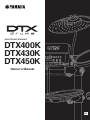
DTX400K/DTX430K/DTX450K Owner’s Manual
1
Owner’s Manual
DTX400K
DTX430K
DTX450K
ELECTRONIC DRUM KIT
EN

DTX400K/DTX430K/DTX450K Owner’s Manual
2
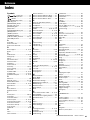
Contents
PRECAUTIONS ............................................ 4
Welcome....................................................... 6
Product Manuals ......................................... 6
Setup
First Steps.................................................... 7
Package Contents ....................................... 8
Assembly Guide .........................................11
Setting Up for Sound ................................ 19
Connecting the Power..................................... 19
Connecting Headphones or Speakers ............ 19
Connecting a Music Player ............................. 19
Turning On the Drum Module.......................... 20
Turning Off the Drum Module.......................... 20
Auto Power-Off ................................................ 20
Restoring the Default Settings (Factory Set) ... 20
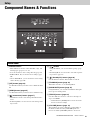
Component Names & Functions.............. 21
Control Panel .................................................. 21
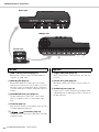
Left Side.......................................................... 22
Right Side ....................................................... 22
Basic Techniques
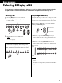
Selecting & Playing a Kit .......................... 23
Selecting a Kit ................................................. 23
Adjusting Kit Sensitivity................................... 23
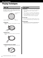
Playing Techniques................................... 24
Snare Pad ....................................................... 24
Hi-hat Cymbal ................................................. 24
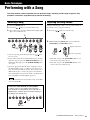
Performing with a Song ............................ 25
Selecting a Song............................................. 25
Adjusting the Song Volume............................. 25
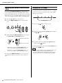
Adjusting the Volume of Muted Drum Parts .... 26
Looping Part of a Song ................................... 26
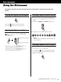
Using the Metronome ............................... 27
Starting and Stopping the Metronome ............ 27
Adjusting the Metronome Volume ................... 27
Confirming Tempo via Number Buttons .......... 27
Confirming Tempo via Voice Guidance ........... 27
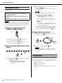
Adjusting the Tempo ....................................... 28
Other Settings ................................................. 28
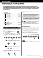
Practicing in Training Mode ......................29
Basic Training Mode Procedure....................... 29
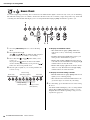
1. Groove Check .............................................. 30
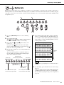
2. Rhythm Gate ............................................... 31
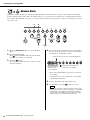
3. Measure Break............................................ 32
4. Tempo Up/Down..........................................33
5. Change Up .................................................. 34
6. Easy Session ..............................................35
7. Groove Tracker............................................. 36
8. Pad Gate ..................................................... 37
9. Part Mute.....................................................38
10. Fast Blast................................................... 39
Advanced Techniques
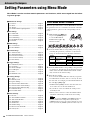
Setting Parameters using Menu Mode..... 40
Basic Menu Mode Procedure ..........................40
z Metronome Settings....................................41
x Kit Settings.................................................. 42
c MIDI Settings .............................................. 44
v Hi-hat Settings ............................................ 45
b Trigger Settings...........................................46
n Training Settings .........................................49
m Other Settings.............................................53
Integrating Separately Sold Accessories
..56
For DTX400K Owners .....................................56
For DTX430K & DTX450K Owners ................. 56
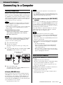
Connecting to a Computer........................57
Making Connections........................................57
MIDI Reference Manual .................................. 57
Reference
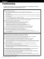
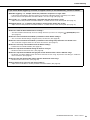
Troubleshooting......................................... 58
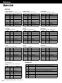
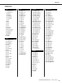
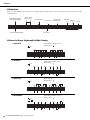
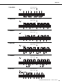
Data List .....................................................60
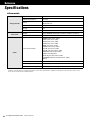
Specifications ............................................64
Index ........................................................... 65

DTX400K/DTX430K/DTX450K Owner’s Manual
3
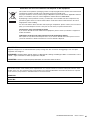
SPECIAL MESSAGE SECTION
This product utilizes batteries or an external power supply (adapter). DO
NOT connect this product to any power supply or adapter other than one
described in the manual, on the name plate, or specifically recommended
by Yamaha.
This product should be used only with the components supplied or; a
cart, rack, or stand that is recommended by Yamaha. If a cart, etc., is
used, please observe all safety markings and instructions that accom-
pany the accessory product.
SPECIFICATIONS SUBJECT TO CHANGE:
The information contained in this manual is believed to be correct at the
time of printing. However, Yamaha reserves the right to change or modify
any of the specifications without notice or obligation to update existing units.
This product, either alone or in combination with an amplifier and head-
phones or speaker/s, may be capable of producing sound levels that could
cause permanent hearing loss. DO NOT operate for long periods of time at
a high volume level or at a level that is uncomfortable. If you experience
any hearing loss or ringing in the ears, you should consult an audiologist.
IMPORTANT: The louder the sound, the shorter the time period
before damage occurs.
NOTICE:
Service charges incurred due to a lack of knowledge relating to how a
function or effect works (when the unit is operating as designed) are not
covered by the manufacturer’s warranty, and are therefore the owners
responsibility. Please study this manual carefully and consult your dealer
before requesting service.
ENVIRONMENTAL ISSUES:
Yamaha strives to produce products that are both user safe and environ-
mentally friendly. We sincerely believe that our products and the production
methods used to produce them, meet these goals. In keeping with both the
letter and the spirit of the law, we want you to be aware of the following:
Battery Notice:
This product MAY contain a small non-rechargeable battery which (if
applicable) is soldered in place. The average life span of this type of bat-
tery is approximately five years. When replacement becomes necessary,
contact a qualified service representative to perform the replacement.
This product may also use “household” type batteries. Some of these may
be rechargeable. Make sure that the battery being charged is a recharge-
able type and that the charger is intended for the battery being charged.
When installing batteries, never mix old batteries with new ones, and
never mix different types of batteries. Batteries MUST be installed cor-
rectly. Mismatches or incorrect installation may result in overheating and
battery case rupture.
Warning:
Do not attempt to disassemble, or incinerate any battery. Keep all batter-
ies away from children. Dispose of used batteries promptly and as regu-
lated by the laws in your area. Note: Check with any retailer of household
type batteries in your area for battery disposal information.
Disposal Notice:
Should this product become damaged beyond repair, or for some reason
its useful life is considered to be at an end, please observe all local,
state, and federal regulations that relate to the disposal of products that
contain lead, batteries, plastics, etc. If your dealer is unable to assist you,
please contact Yamaha directly.
NAME PLATE LOCATION:
The name plate is located on the bottom of the product. The model num-
ber, serial number, power requirements, etc., are located on this plate.
You should record the model number, serial number, and the date of pur-
chase in the spaces provided below and retain this manual as a perma-
nent record of your purchase.
Model
Serial No.
Purchase Date
PLEASE KEEP THIS MANUAL
92-BP (bottom)
1. IMPORTANT NOTICE: DO NOT MODIFY THIS UNIT!
This product, when installed as indicated in the instructions contained
in this manual, meets FCC requirements. Modifications not expressly
approved by Yamaha may void your authority, granted by the FCC, to
use the product.
2. IMPORTANT: When connecting this product to accessories and/or
another product use only high quality shielded cables. Cable/s sup-
plied with this product MUST be used. Follow all installation instruc-
tions. Failure to follow instructions could void your FCC authorization
to use this product in the USA.
3. NOTE: This product has been tested and found to comply with the
requirements listed in FCC Regulations, Part 15 for Class “B” digital
devices. Compliance with these requirements provides a reasonable
level of assurance that your use of this product in a residential envi-
ronment will not result in harmful interference with other electronic
devices. This equipment generates/uses radio frequencies and, if not
installed and used according to the instructions found in the users
manual, may cause interference harmful to the operation of other
electronic devices. Compliance with FCC regulations does not guar-
antee that interference will not occur in all installations. If this product
is found to be the source of interference, which can be determined by
turning the unit “OFF” and “ON”, please try to eliminate the problem by
using one of the following measures:
Relocate either this product or the device that is being affected by the
interference.
Utilize power outlets that are on different branch (circuit breaker or
fuse) circuits or install AC line filter/s.
In the case of radio or TV interference, relocate/reorient the antenna.
If the antenna lead-in is 300 ohm ribbon lead, change the lead-in to
co-axial type cable.
If these corrective measures do not produce satisfactory results,
please contact the local retailer authorized to distribute this type of
product. If you can not locate the appropriate retailer, please contact
Yamaha Corporation of America, Electronic Service Division, 6600
Orangethorpe Ave, Buena Park, CA90620
The above statements apply ONLY to those products distributed by
Yamaha Corporation of America or its subsidiaries.
* This applies only to products distributed by YAMAHA CORPORATION OF AMERICA. (class B)
FCC INFORMATION (U.S.A.)
Responsible Party : Yamaha Corporation of America
Address : 6600 Orangethorpe Ave., Buena Park, Calif. 90620
Telephone : 714-522-9011
Type of Equipment : ELECTRONIC DRUM KIT
Model Name : DTX400K/DTX430K/DTX450K
This device complies with Part 15 of the FCC Rules.
Operation is subject to the following two conditions:
1) this device may not cause harmful interference, and
2) this device must accept any interference received including interfer-
ence that may cause undesired operation.
See user manual instructions if interference to radio reception is suspected.
* This applies only to products distributed by YAMAHA CORPORATION OF AMERICA. (FCC DoC)
COMPLIANCE INFORMATION STATEMENT (DECLARATION OF CONFORMITY PROCEDURE)

DTX400K/DTX430K/DTX450K Owner’s Manual
4
PRECAUTIONS
PLEASE READ CAREFULLY BEFORE PROCEEDING
Please keep this manual in a safe and handy place for future reference.
WARNING
Always follow the basic precautions listed below to avoid the possibility of serious injury or even death from electrical
shock, short-circuiting, damages, fire or other hazards. These precautions include, but are not limited to, the
following:
• Do not place the power cord near heat sources such as heaters or radiators. Also,
do not excessively bend or otherwise damage the cord, or place heavy objects on it.
• Only use the voltage specified as correct for the instrument. The required voltage
is printed on the name plate of the instrument.
• Use the specified adaptor (page 64) only. Using the wrong adaptor can result in
damage to the instrument or overheating.
• Check the electric plug periodically and remove any dirt or dust which may have
accumulated on it.
• Under no circumstances should any of the components of this product be taken apart
or customized. Doing so could result in electric shock, fire, injury, or malfunction.
• Do not sit or stand on the rack. Doing so could cause it to fall over or break,
possibly causing injury.
• Be careful with the holders for cymbal and tom pads as they have sharp tips. In
order to avoid injury, therefore, you should take special care whenever handling
these components.
• Be careful with the anti-slip stoppers on kick pads and foot pedals as they have
sharp tips. In order to avoid injury, therefore, you should take special care
whenever handling these components.
• Securely tighten fixing nuts and other fasteners. In addition, be sure to immediately
tighten any nuts that have come loose. If this precaution is not observed, pads may
fall off or the rack may collapse or fall over, possibly causing injury.
• Take care when setting up cables. If anyone were to trip on a cable, the instrument
could topple over and cause injury.
• Do not expose the instrument to rain, use it near water or in damp or wet conditions,
place on it any containers (such as vases, bottles or glasses) containing liquids
which might spill into any openings. If any liquid such as water seeps into the
instrument, turn off the power immediately and unplug the power cord from the AC
outlet. Then have the instrument inspected by qualified Yamaha service personnel.
• Never insert or remove an electric plug with wet hands.
• Do not put burning items, such as candles, on the unit. A burning item may fall
over and cause a fire.
• When one of the following problems occur, immediately turn off the power switch
and disconnect the electric plug from the outlet. Then have the device inspected by
Yamaha service personnel.
- The power cord or plug becomes frayed or damaged.
- It emits unusual smells or smoke.
- Some object has been dropped into the instrument.
- There is a sudden loss of sound during use of the instrument.
CAUTION
Always follow the basic precautions listed below to avoid the possibility of physical injury to you or others, or damage
to the instrument or other property. These precautions include, but are not limited to, the following:
• Do not connect the instrument to an electrical outlet using a multiple-connector.
Doing so can result in lower sound quality, or possibly cause overheating in the
outlet.
• When removing the electric plug from the instrument or an outlet, always hold the
plug itself and not the cord. Pulling by the cord can damage it.
• Remove the electric plug from the outlet when the instrument is not to be used for
extended periods of time, or during electrical storms.
• Read carefully the attached documentation explaining the assembly process.
Failure to assemble the instrument in the proper sequence might result in damage
to the instrument or even injury.
• Do not place hands or feet under a foot switch or foot pedal. Doing so could result
in injury.
• Do not use the electronic drum kit’s rack to hold acoustic drums. Doing so could
cause clamps to break and the drums to fall off, which in turn could lead to injury.
• Mind your fingers when adjusting clamps. Fingers can easily be caught and
crushed if care is not taken during this operation.
• Be careful with the tips of supports, arms, screws, and the like. Fingers can easily
be injured by sharp tips if these components are not handled carefully.
• Do not place the instrument in an unstable position where it might accidentally fall
over.
• Before moving the instrument, remove all connected cables, to prevent damage to
the cables or injury to anyone who might trip over them.
Power supply/AC power adaptor
Assembly
Water warning
Fire warning
If you notice any abnormality
Power supply/AC power adaptor
Assembly
Location
DMI-5 1/2

DTX400K/DTX430K/DTX450K Owner’s Manual
5
• When setting up the product, make sure that the AC outlet you are using is easily
accessible. If some trouble or malfunction occurs, immediately turn off the power
switch and disconnect the plug from the outlet. Even when the power switch is
turned off, electricity is still flowing to the product at the minimum level. When
you are not using the product for a long time, make sure to unplug the power cord
from the wall AC outlet.
• Use only the stand/rack specified for the instrument. When attaching the stand or
rack, use the provided screws only. Failure to do so could cause damage to the
internal components or result in the instrument falling over.
• Before connecting the instrument to other electronic components, turn off the
power for all components. Before turning the power on or off for all components,
set all volume levels to minimum.
• Be sure to set the volumes of all components at their minimum levels and
gradually raise the volume controls while playing the instrument to set the desired
listening level.
• Do not insert a finger or hand in any gaps on the instrument.
• Never insert or drop paper, metallic, or other objects into the gaps on the panel.
This could cause physical injury to you or others, damage to the instrument or
other property, or operational failure.
• Do not rest your weight on, or place heavy objects on the instrument, and do not
use excessive force on the buttons, switches or connectors.
• Do not use the instrument/device or headphones for a long period of time at a high
or uncomfortable volume level, since this can cause permanent hearing loss. If
you experience any hearing loss or ringing in the ears, consult a physician.
Always turn the power off when the instrument is not in use.
Even when the [ ] (Standby/On) switch is in standby status (power lamp is off), electricity is still flowing to the instrument at the minimum level.
When you are not using the instrument for a long time, make sure you unplug the power cord from the wall AC outlet.
NOTICE
To avoid the possibility of malfunction/damage to the prod-
uct, damage to data, or damage to other property, follow
the notices below.
Handling and Maintenance
• Do not use the instrument in the vicinity of a TV, radio,
stereo equipment, mobile phone, or other electric
devices. Otherwise, the instrument, TV, or radio may
generate noise.
• Do not expose the instrument to excessive dust or vibra-
tions, or extreme cold or heat (such as in direct sunlight,
near a heater, or in a car during the day) to prevent the
possibility of panel disfiguration, damage to the internal
components or unstable operation. (Verified operating
temperature range: 5° – 40°C, or 41° – 104°F.)
• Do not place vinyl, plastic or rubber objects on the
instrument, since this might discolor the panel or key-
board.
• When cleaning the drum module, be sure to use a clean,
dry cloth. Cleaning products that contain organic sol-
vents, paint thinner, detergents, and chemically-treated
cleaning cloths can cause discoloration and/or warping
and should not be used.
• When cleaning the pads, avoid cleaning products that
contain organic solvents, paint thinner, and alcohol as
they can cause discoloration and/or warping. Instead,
we recommend that you remove dust using a soft dry
cloth or wipe clean with a moist, tightly-wrung-out cloth.
If a pad is very dirty, wipe the dirt away using a cloth
moistened with a neutral detergent solution and tightly
wrung out. Following this, wipe away the detergent solu-
tion using a cloth soaked in water and tightly wrung out.
Information
About copyrights
• Copying of the commercially available musical data including but
not limited to MIDI data and/or audio data is strictly prohibited
except for your personal use.
• This product incorporates and bundles computer programs and
contents in which Yamaha owns copyrights or with respect to
which it has license to use others’ copyrights. Such copyrighted
materials include, without limitation, all computer software, style
files, MIDI files, WAVE data, musical scores and sound record-
ings. Any unauthorized use of such programs and contents out-
side of personal use is not permitted under relevant laws. Any
violation of copyright has legal consequences. DON’T MAKE,
DISTRIBUTE OR USE ILLEGAL COPIES.
About this manual
• The illustrations as shown in this manual are for instructional
purposes only, and may appear somewhat different from those
on your instrument.
• The company names and product names in this manual are the
trademarks or registered trademarks of their respective compa-
nies.
Connections
Handling caution
Yamaha cannot be held responsible for damage caused by improper use or modifications to the instrument, or data that is lost or destroyed.
Optional Pads
Within this Owner’s Manual, the optional external pads that may be connected to the drum module are referred to by
model name. Please note that these model names were up-to-date as of printing of this manual. Details regarding any
subsequently released models will be made available via the following web site.
http://www.yamaha.com/
DMI-5 2/2

DTX400K/DTX430K/DTX450K Owner’s Manual
6
Welcome
First of all, thank you for purchasing a Yamaha DTX400K, DTX430K, or DTX450K
Electronic Drum Kit. In order to get the most out of your new instrument, please be
sure to read this owner’s manual carefully. And after doing so, be sure to store it in a
safe place so that you can refer back to it again as needed.
Product Manuals
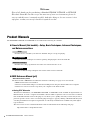
The DTX400K, DTX430K, and DTX450K are described in the following two manuals.
Owner’s Manual (this booklet)—Setup, Basic Techniques, Advanced Techniques,
and Reference sections.
Describes how to assemble your electronic drum kit and get it set up for playing.
Describes the basic techniques used when operating and playing the electronic drum kit.
Describes the setting of parameters and other more advanced modes of use.
Describes troubleshooting techniques and contains other reference materials.
MIDI Reference Manual (pdf)
* Not bundled with this product.
The drum module’s MIDI Reference Manual contains the following. See page 57 for more details.
• MIDI-related reference information
• Reference material that will prove useful when making music using the drum module and a computer
• Instructions on how to transfer songs from your computer to the drum module
Using PDF Manuals
The Reference Manual for your DTX400K, DTX430K, or DTX450K is made available in digital format as a
PDF document. As such, a computer and suitable software will be required in order to read it. We recommend
that Adobe® Reader® be used for this purpose as it allows you to quickly and easily search for keywords, to
print out specific sections, and to conveniently jump from page to page by clicking embedded links. Keyword
searching and link-based navigation in particular are extremely useful functions available only with digital-
type documents.
The most-recent version of Adobe® Reader® can be downloaded from the following web page.
http://www.adobe.com/products/reader/
Setup
Basic Techniques
Advanced Techniques
Reference

Setup
DTX400K/DTX430K/DTX450K Owner’s Manual
7
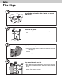
First Steps
1
2
3
4
Open the box and confirm that all parts are present
and correct.
Assemble the parts.
• The assembly process is described in detail on pages 8 through
18.
Make the necessary connections.
• Connect the pads to the drum module using the cables provided.
See page 18.
• Connect the power adaptor to the drum module and turn on the
module.
See page 19.
Play your electronic drum kit.
• Basic techniques used when operating and playing the electronic
drum kit are described in the Basic Techniques section (pages 23
to 39).
• More complex methods are described in the Advanced Tech-
niques section (pages 40 to 55).
Setup

Setup
DTX400K/DTX430K/DTX450K Owner’s Manual
8
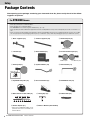
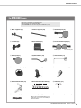
Package Contents
After opening up the package containing your electronic drum kit, please verify that all of the follow-
ing parts are present.
For DTX400K Owners
•Parts !6, !7, and !8 are contained in Box 1.
•Parts !0 and !1 are contained in Box 2.
• The DTX400K does not have any parts numbered u, o, or !3.
•Parts !4 and !5 are almost identical in appearance but are actually different. They can be told apart by the sticker on the base sec-
tion.
•Parts e and i are almost identical in appearance but are actually different. Part i has a wing bolt, but part e does not. In addi-
tion, the polystyrene foam packaging used for part e is marked “T” (tom); while the packaging for part i is marked “S” (snare).
q Base supports (x2) w Vertical supports (x2) e Third tom part (x1)
r Left arm (x1) t Drum module (x1) y First/second tom part (x1)
Third tom pad
First tom pad Second tom pad
i Snare pad (x1) !0 Cymbal holders (x2) !1 Hi-hat holder (x1)
Rear side
Wing bolt
!2 Cymbal/hi-hat pads (x3) !4 Hi-hat controller (x1) !5 KU100 Kick Unit (x1)
!6 Nine-channel snake cable (x1) !7 Tuning key (x1) !8 Cable bands (x3)
!9 Power adaptor (x1) @0 Owner’s Manual (this booklet)
* May not be included depending on your
particular area. Please check with your
Yamaha dealer.

Package Contents
DTX400K/DTX430K/DTX450K Owner’s Manual
9
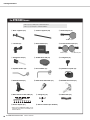
For DTX430K Owners
•Parts !6, !7, and !8 are contained in Box 1.
•Parts !0 and !1 are contained in Box 2.
• The DTX430K does not have any parts numbered u or o.
q Base supports (x2) w Vertical supports (x2) e Third tom part (x1)
t Drum module (x1) y First/second tom part (x1)
!0 Cymbal holders (x2) !1 Hi-hat holder (x1)
!2 Cymbal/hi-hat pads (x3) !3 KP65 Kick Pad (x1) !4 HH65 Hi-hat Controller (x1)
r Left arm (x1)
i Snare pad (x1)
!5 FP6110A Foot Pedal (x1) !6 Nine-channel snake cable (x1) !7 Tuning key (x1)
!8 Cable bands (x3) !9 Power adaptor (x1) @0 Owner’s Manual (this booklet)
* May not be included depending on your
particular area. Please check with your
Yamaha dealer.
Third tom pad
First tom pad Second tom pad

Package Contents
DTX400K/DTX430K/DTX450K Owner’s Manual
10
For DTX450K Owners
•Parts o, !6, !7, and !8 are contained in Box 1.
•Parts u, !0, and !1 are contained in Box 2.
q Base supports (x2) w Vertical supports (x2) e Third tom part (x1)
t Drum module (x1) y First/second tom part (x1)
!0 Cymbal holders (x2) !1 Hi-hat holder (x1) !2 Cymbal/hi-hat pads (x3)
!3 KP65 Kick Pad (x1) !4 HH65 Hi-hat Controller (x1)
r Left arm (x1)
!5 FP6110A Foot Pedal (x1)
!6 Nine-channel snake cable (x1) !7 Tuning key (x1) !8 Cable bands (x3)
!9 Power adaptor (x1) @0 Owner’s Manual (this booklet)
* May not be included depending on your
particular area. Please check with your
Yamaha dealer.
Third tom pad
First tom pad Second tom pad
i TP70S Snare Pad (x1) o S wing bolt (x1)u Hexagonal rod (x1)

Setup
DTX400K/DTX430K/DTX450K Owner’s Manual
11
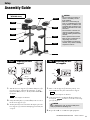
Assembly Guide
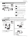
Preparing the base
supports
1. Take the two base supports (q) and the tuning key (!7)
from the package, and using the tuning key, securely
tighten the s key bolts (i.e., the key bolts labeled s in
the figure).
2. Using the tuning key, loosen the key bolt on each of
the two base supports (q).
3. Viewing from the front as shown in the figure, place the
base supports (q) at the left and right approximately 50
cm apart.
Attaching the verti-
cal supports
1. Take a vertical support (w) from the package, and
insert it fully into the joint on the left base support.
2. Using the tuning key, tighten the key bolt that you
loosened in in order to secure the vertical sup-
port (w) in place.
3. Repeat 1. and 2. to assemble the right upright bar.
Fully assembled drum kit
(DTX450K shown)
CAUTION
• Choose a flat, hard surface on
which to assemble your elec-
tronic drum kit.
• Take care to avoid mixing up
parts or assembling them in the
wrong direction. In addition, the
assembly steps should be com-
pleted one at a time in the order
described.
• The assistance of at least one
other person will be required
when assembling the electronic
drum kit.
• Once a piece has been assem-
bled, be sure to tighten the cor-
responding nuts or bolts.
• To disassemble your electronic
drum kit, carry out the assembly
sequence in reverse.
Step 5
Step 10
Step 8
Step 4
Step 7
Step 6
Step 11
Step 9
Step 3
Step 2
Step 1
The two base supports are identical.
Step 1
!7
q
q
50 cm
Front
NOTE
The two vertical supports are identical.
CAUTION
After completing this step, lay the assembly down
safely to prevent it from falling over.
Step 2
w
Joint
Left
Right
NOTE
Step 1

Assembly Guide
DTX400K/DTX430K/DTX450K Owner’s Manual
12
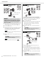
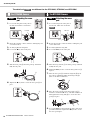
Attaching the third
tom part
1. Take the third tom part (e) from the package, and
using the tuning key, securely tighten the s key bolt.
2. Loosen the key bolt.
3. Slide the third tom part (e) onto the right vertical sup-
port and lower it to the center of the support or there-
abouts. Ensure that the third tom pad is oriented as
shown in the above figure at this time.
4. Tighten the key bolt to secure the third tom part (e)
in place.
Attaching the left
arm
1. Take the left arm (r) from the package, and using the
tuning key, securely tighten the s key bolt.
2. Loosen the key bolt.
3. Slide the left arm (r) onto the left vertical support and
lower it to the center of the support or thereabouts.
Ensure that the left arm is oriented as shown in the
above figure at this time.
4. Tighten the key bolt to secure the left arm (r) in
place.
Attaching the drum
module
1. Take the drum module (t) from the package and
loosen the
key bolt.
2. Slide the drum module (t ) onto the left vertical sup-
port and lower it to a position about 10 cm from the top.
The angle at which the module should be assembled is
shown in the figure.
3. Tighten the key bolt to secure the drum module (t)
in place.
IMPORTANT
The third tom part (e) and the snare part (i) from the
DTX400K are almost identical in appearance, and special
care should be taken to avoid mixing them up during the
assembly process. To tell them apart, look for the wing
bolt, which is only found on part i. See the figure on
page 8 for more details.
Care should be taken to avoid assembling the third tom pad
upside-down or back-to-front.
CAUTION
After completing this step, lay the assembly down
safely to prevent it from falling over.
The third tom pad will be rotated into place in .
Step 3
e
Rear of third tom pad
Right vertical support
NOTE
NOTE
Step 12
The joint shown in the figure is not part of the DTX400K.
CAUTION
After completing this step, lay the assembly down
safely to prevent it from falling over.
CAUTION
After completing this step, lay the assembly down
safely to prevent it from falling over.
Step 4
r
Joint
Left vertical
support
Step 5
t
10 cm
Left vertical support

Assembly Guide
DTX400K/DTX430K/DTX450K Owner’s Manual
13
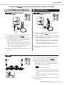
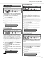
Attaching the first/second tom part
1. Take the first/second tom part (y) from the package,
and using the tuning key, securely tighten the s key
bolts.
2. Loosen the key bolts.
3. Slide the first/second tom part (y) onto the vertical
supports and move it down until the tops of the supports
are flush with the tops of the holes. Ensure that the tom
part is oriented as shown in the above figure at this time.
4. Tighten the key bolts to secure the first/second tom
part (y) in place.
The details of are different for the DTX400K, DTX430K, and DTX450K.
Attaching the snare
pad
1. Take the snare part (i) from the pack-
age and lightly tighten the wing bolt.
2. Place the snare part (i) on the left arm, which was
assembled in , and slide it back until the front
end of the arm is flush with the joint.
3. Securely tighten the wing bolt.
4. Loosen the key bolt located on the back of the snare
pad (i), and rotate the pad 180°, turning it over.
5. Tighten the key bolt to secure the snare pad (i) in
place.
Step 6
y
Rear of first tom pad
Rear of second
tom pad
Vertical supports
This part has two s key bolts, one each on the left and right.
This part has two
key bolts, one each on the left and right.
Care should be taken to avoid assembling the first and sec-
ond tom pads upside-down or back-to-front.
The tom pads will be rotated into place in .
NOTE
NOTE
NOTE
NOTE
Step 12
Step 7
For DTX400K Owners
Step 7
i
Wing bolt
Left arm
Joint
Step 4
i
180°
i

Assembly Guide
DTX400K/DTX430K/DTX450K Owner’s Manual
14
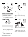
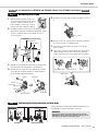
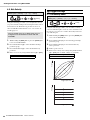
The details of are different for the DTX400K, DTX430K, and DTX450K.
Attaching the snare
pad
1. Loosen the wing bolt on the joint on
the left arm, which was attached in
.
2. Rotate the joint 90° counter-clockwise, making the joint
section horizontal.
3. Securely tighten the wing bolt.
4. Loosen the key bolt on the joint.
5. Take the snare pad (i) from the package and slide it
fully into the joint.
6. Tighten the key bolt to secure the snare pad (i) in
place.
Attaching the snare
pad
1. Loosen the wing bolt on the joint on
the left arm, which was attached in
.
2. Rotate the joint 90° counter-clockwise, making the joint
section horizontal.
3. Securely tighten the wing bolt.
4. Loosen the key bolt on the joint.
5. Take the hexagonal rod (u) from the package and slide
it fully into the joint.
6. Tighten the key bolt to secure the hexagonal rod (u)
in place.
7. Take the snare pad (i) and the S wing bolt (o) from
the package and lightly tighten the S wing bolt (o).
(Five or six turns is sufficient.)
8. Place the snare pad (i ) on the hexagonal rod (u),
which was attached in
6. above, and slide it fully back.
Then tighten the S wing bolt (o) to secure the snare
pad (i) in place.
9. Loosen the key bolt and adjust the angle of the snare
pad. When finished, retighten the key bolt to secure
the snare pad in place.
Step 7
For DTX430K Owners For DTX450K Owners
Step 7
Step 4
Left arm
Wing bolt
Joint
90°
i
i
Step 7
Step 4
Left arm
Wing bolt
Joint
90°
u
o
i
u
i
o

Assembly Guide
DTX400K/DTX430K/DTX450K Owner’s Manual
15
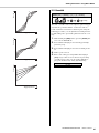
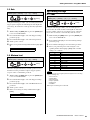
The details of are different for the DTX400K, DTX430K, and DTX450K.
Attaching the hi-hat
holder
1. Loosen the two key bolts on the joint on the snare-
pad part, which was attached in .
2. Take the hi-hat holder (!1) from the package and slide it
into the joint from the front as shown in the figure. Then
adjust the angle of the hi-hat holder.
• When correctly inserted, the tip of the hi-hat holder
(!1) will protrude slightly from the rear of the joint.
• When correctly oriented, the metal rod section at the
top of the hi-hat holder (!1) will be vertical.
3. Tighten the two key bolts to secure the hi-hat holder
(!1) in place.
Attaching the hi-hat
holder
1. Loosen the two key bolts on the joint on the left arm,
which was attached in .
2. Take the hi-hat holder (!1) from the package and slide it
into the joint from the rear as shown in the figure. Then
adjust the angle of the hi-hat holder.
• When correctly inserted, the tip of the hi-hat holder
(!1) will protrude slightly from the front of the joint.
• When correctly oriented, the metal rod section at the
top of the hi-hat holder (!1) will be vertical.
3. Tighten the two key bolts to secure the hi-hat holder
(!1) in place.
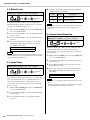
Attaching the cymbal holders
1. Loosen the four key bolts at the ends of the first/sec-
ond tom part, which was attached in .
2. Take the cymbal holders (!0) from the package and
insert them into the ends of the first/second tom part.
Then adjust the angles of the cymbal holders until they
are oriented as shown in the figure.
• When correctly inserted, the tips of the cymbal hold-
ers (!0) will protrude slightly from the bottom of the
tom part.
• When correctly oriented, the cymbal holders (!0) will
be as shown in the figure.
3. Tighten the four key bolts to secure the cymbal hold-
ers (!0) in place.
Step 8
For DTX400K and DTX430K Owners For DTX450K Owners
Step 8
!1
Snare pad
Joint
Step 7
Step 8
!1
Left arm
Joint
Step 4
Step 9
!0!0
The two cymbal holders are identical.
Step 6
NOTE

Assembly Guide
DTX400K/DTX430K/DTX450K Owner’s Manual
16
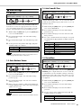
Attaching the hi-hat
Adjusting the position of the hi-
hat stopper pin
1. Using the tuning key, loosen the key bolt on the
stopper, which is located at the top of the hi-hat holder.
2. Adjust the position of the pin until, as shown in the fig-
ure, it is approximately 30° counter-clockwise from the
front-rear direction of the kit when viewed from above.
3. Tighten the key bolt to secure the stopper pin.
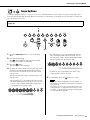
Assembling the hi-hat pad
1. Remove the wing nut, the washer, and the upper felt pad
from the hi-hat holder. (Do not remove the lower felt
pad.)
2. Take the hi-hat pad (!2; one of three) from the package
and place it on the hi-hat holder with the stopper pin
also passing through the hole provided.
3. Replace the felt pad removed in 1. above the hi-hat pad
(!2).
4. Replace the washer removed in 1. above the felt pad.
5. Tighten the wing nut to secure the hi-hat pad (!2) in
place. Ensure that the wing nut is firmly tightened.
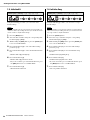
Assembling the cym-
bal pads
In this step, the two remaining cymbal/hi-hat pads (!2) are
assembled. Accordingly,
1. to 4. must be performed twice.
1. Remove the wing nut and the upper felt pad from the
cymbal holder. (Do not remove the lower felt pad.)
2. Place the cymbal pad (!2) on the cymbal holder, with
the holder passing through the central hole.
3. Replace the felt pad removed in 1. above the cymbal
pad (!2).
4. Tighten the wing nut to secure the cymbal pad (!2) in
place.
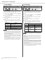
Rotating the tom
pads into place
applies to each of the three tom pads. Accord-
ingly,
1. to 3. must be performed three times.
1. Loosen the key bolt on the tom pad (e or y).
2. Rotate the tom pad to a position where it will be easy to
play. (If necessary, refer to the picture of the properly
assembled kit on page 11.)
3. Tighten the key bolt to secure the tom pad in place.
This figure shows the hi-hat holder correctly inserted in
the DTX450K. It is inserted from the front in the DTX400K
and DTX430K, and therefore, faces in the opposite direc-
tion.
All three of the cymbal/hi-hat pads (!2) are identical. One
of these is to be used as the hi-hat pad.
Step 10
Pin
30°
30°
Pin
Front
Stopper
Hi-hat holder
Front
!2
Wing nut
Felt pad
Felt pad
Hi-hat holder
Stopper
Washer
The two cymbal pads (!2) are identical.
Step 11
!2
Wing nut
Felt pad
Felt pad
Cymbal holder
NOTE
Step 12
e
y
Step 12

Assembly Guide
DTX400K/DTX430K/DTX450K Owner’s Manual
17
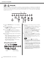
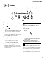
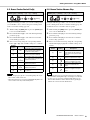
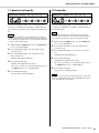
is only required for the DTX430K and DTX450K. Owners of the DTX400K should skip to .
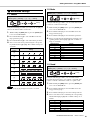
Assembling the kick pad
1. Take the kick pad (!3) from the pack-
age, remove the four wing bolts, spring
washers, and flat washers from the
kick pad holder, and arrange each set
nearby in the disassembled condition.
2. Assemble the base to the holder as shown below, and
then from the base side, assemble the wing bolts, spring
washers, and flat washers removed in
1. in order to
secure it in place.
3. Take the foot pedal (!5) from the package and insert the
beater into the hole in the holder as shown below.
4. Slide the beater rod into the hole until the tip protrudes
approximately 15 mm from the rear, and then tighten
the beater bolt using the tuning key.
5. Turn the foot pedal’s T-bolt counter-clockwise to loosen
it.
6. Fit the raised section at the front of the kick pad holder
into the foot-pedal’s assembly bracket.
7. Turn the foot pedal’s T-bolt clockwise to secure the
parts together.
8. Operate the pedal and confirm whether the beater head
strikes the kick pad near the center. If not, adjust the
length of the beater or move it left or right as required.
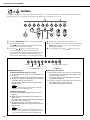
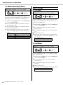
Positioning the hi-hat controller and kick drum
Arrange the hi-hat controller (!4) and the kick drum parts or
kick unit (!5) as shown in the figure on the left.
Step 13
Step 14
Step 13
!3
Wing bolt
Spring washer
Flat washer
Kick pad
Kick padBase
!5
Beater Tuning key
Holder
Connecting
rod
Connecting rod
Beater bolt
T- b o l t
Beater head
Assembly bracket Raised section T-bolt
Step 14
DTX400K
!4
!4
!5
DTX430K/DTX450K
Kick drum parts
IMPORTANT
The hi-hat controller (!4) and the kick unit (!5) from the
DTX400K are almost identical in appearance. They can be
told apart by the sticker on the base section.

Assembly Guide
DTX400K/DTX430K/DTX450K Owner’s Manual
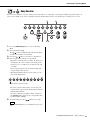
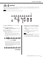
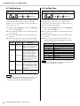
18
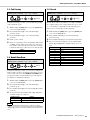
Fine-tuning the positions of the pads and the drum module
Sit on your stool and adjust the positions of the pads and the
drum module to your liking.
• To adjust the height of the snare pad, loosen the
key bolt.
• To adjust the height of the third tom pad, loosen the
key bolt.
• To adjust the height of the drum module, loosen the
s
key bolt.
• To tilt the drum module forwards or backwards, loosen the
key bolt.
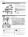
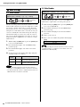
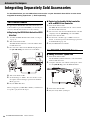
Connecting the pads to the drum module
1. Insert the mini plugs* at one end of the nine-channel
snake cable (!6) into the correct trigger input jacks
(SNARE to KICK/PAD) on the right side of the drum
module. (*: The smaller set of plugs.)
2. Insert the nine-channel snake cable’s standard plugs*
into the jacks in the corresponding pads. (*: The larger
set of plugs.)
3. Wrap the cables for the snare pad, the tom pads, and the
cymbal/hi-hat pads around the cable clips to prevent
them from being pulled out.
4. Using the cable bands (!8), secure the cables to the kit
rack at the positions in the figure above.
Congratulations—You have finished assembling
your electronic drum kit!
Step 15
Drum module
Snare pad
Third tom
pad
CAUTION
• Be sure to always retighten any key bolt after you have
finished adjusting the corresponding part.
• Before moving on to the next step, ensure that all key
bolts have been tightened.
• Refer back to if you wish to readjust the angle of the
snare pad.
• Refer back to if you wish to readjust the angles of the
tom pads.
NOTE
Step 7
Step 12
Step 16
RIDESNRHH
KICKHHCHHCRRIDETOM3TOM2TOM1SNR
TOM2TOM1CR TOM3 KICK HHC
RIDE
SNR
HH
KICK
HHC
TOM3
TOM2
TOM1
CR
KICK HHC
DTX400K
Right side of the drum module
Nine-channel snake cable
The sticker on each of the snake cable’s plugs indicates the
name of the corresponding pad.
NOTE
Excessive bending can damage the cables. Ensure, there-
fore, that they are not bent at an extreme angle when
wrapped around the clips.
NOTICE

Setup
DTX400K/DTX430K/DTX450K Owner’s Manual
19
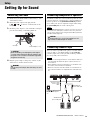
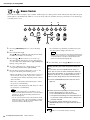
Setting Up for Sound
1. Ensure that your drum module is turned off (i.e., none
of the buttons are lit).
2. Insert the power adaptor’s DC plug into the
[] connector on the left side of the
module.
3. Hook the power adaptor’s cord around the cord clip to
prevent it from being accidentally pulled out.
4. Plug the power adaptor’s AC power cord into an AC
wall socket or another electrical outlet.
Your drum module does not have built-in speakers. In order
to hear it, therefore, you will need to connect headphones or
monitor speakers via the [PHONES/OUTPUT] standard
stereo-audio jack. You can adjust the output volume using
the [VOLUME] buttons on the control panel.
You can connect a portable music player or another similar
source of audio to your drum module via the [AUX IN]
(auxiliary input) stereo mini-jack. This makes it possible to
play along with your favorite tunes.
Connecting the Power
CAUTION
Excessive bending can damage the power adaptor
cord and create a fire hazard. Ensure, therefore, that
the power cord is not bent at an extreme angle when
wrapped around the clip.
WARNING
Use only the power adaptor that came with your drum
module.
Cord clip
Power adaptor’s cord
Connecting Headphones or Speakers
The [PHONES/OUTPUT] jack is a stereo connector. You can con-
nect a 1/4” mono-audio jack to it, but in such a case, please be
sure to set the output to mono using the Stereo/Mono parameter
from Menu Mode (page 53).
CAUTION
To prevent hearing loss, avoid using headphones at a
high volume for extended periods of time.
Connecting a Music Player
• Whenever connecting other devices, ensure that the cables you
use have plugs that match the input or output connectors on
those devices.
• Before making connections, furthermore, you should also turn
the volume on the other devices fully down.
• When all connections have been made, use each device’s vol-
ume controller to balance its output with that of the drum mod-
ule.
NOTE
NOTICE
1/8” stereo-mini
to stereo-mini
cable
Portable music player,
etc.
Standard 1/4”
mono-audio jack
Powered speakers
or
Standard 1/4”
stereo-audio jack
Headphones

Setting Up for Sound
DTX400K/DTX430K/DTX450K Owner’s Manual
20
1. If you have connected your drum module to other audio
devices such as powered speakers, ensure that the vol-
ume on all other devices is turned down fully.
2. Press the [ ] (Standby/On) button.
The drum module will turn on and its buttons will light up.
1. If you have connected your drum module to other audio
equipment, ensure that the volume on all other devices
is turned down fully.
2. Press the [ ] (Standby/On) button.
The drum module will turn off and all button lights will
go out.
The Auto Power-Off function automatically turns off the
drum module after a certain period of inactivity. This helps
to save energy should you forget to turn it off yourself.
Setting the Auto Power-Off Function
You can set the amount of time that the Auto Power-Off
function will wait before turning off the drum module. For
details, see the description of the Auto Power-Off Time
parameter from Menu Mode (page 53).
Quickly disabling Auto Power-Off
To quickly disable the Auto Power-Off function, turn on the
drum module while holding down the [TRAINING] button.
The function will remain off until you set a new Auto
Power-Off time.
Straight out of the box, your drum module already contains
a wide range of pre-programmed drum kits and songs.
These default settings—collectively known as the Factory
Set—can be conveniently restored at any time if you have
accidentally overwritten them or wish to delete all of your
own settings. To do so, use the Factory Set function as fol-
lows.
1. Press the [ ] (Standby/On) button and verify that the
drum module turns off.
2. Turn on the drum module while holding down the
[VOLUME+] button and the [VOLUME–] button.
The drum module’s lights will flash and the Factory Set
will be restored.
Turning On the Drum Module
Connect the hi-hat controller before turning on the drum
module. Please do not turn the drum module on with the hi-
hat controller depressed. The drum module can not identify
the type of pedal properly and it causes that the kick may
produce much smaller sound than expected.
Turning Off the Drum Module
CAUTION
When setting up the product, make sure that the AC
outlet you are using is easily accessible. If some trou-
ble or malfunction occurs, immediately turn off the
power switch and disconnect the plug from the outlet.
Even when the power switch is turned off, electricity is
still flowing to the product at the minimum level. When
you are not using the product for a long time, make
sure to unplug the power cord from the wall AC outlet.
The drum module automatically stores all current settings
before it turns off. For this reason, please do not unplug the
power adaptor until all button lights have gone out.
Auto Power-Off
The drum module automatically stores all current settings before
it turns off.
NOTE
NOTICE
NOTE
• In certain modes of operation, the Auto Power-Off function will
not turn off the drum module when the set time has elapsed. We
recommend, therefore, that you always turn off the drum module
manually when you are finished using it.
• If you expect the drum module to be inactive for a certain length
of time while connected to other audio equipment, we recom-
mend that you turn the volume on the other equipment fully
down. Alternatively, you can disable the Auto Power-Off function
to ensure that the drum module stays on.
• Settings for the Auto Power-Off function do not represent exact
times and there may be some variation.
• By default, the Auto Power-Off time is set to 30 minutes.
Restoring the Default Settings
(Factory Set)
When you restore the Factory Set as described below, any
changes you have made to parameters will be lost. Before pro-
ceeding, therefore, you should ensure that they contain no irre-
placeable settings.
NOTICE
NOTE
Hold
NOTICE
Hold
Страница загружается ...
Страница загружается ...
Страница загружается ...
Страница загружается ...
Страница загружается ...
Страница загружается ...
Страница загружается ...
Страница загружается ...
Страница загружается ...
Страница загружается ...
Страница загружается ...
Страница загружается ...
Страница загружается ...
Страница загружается ...
Страница загружается ...
Страница загружается ...
Страница загружается ...
Страница загружается ...
Страница загружается ...
Страница загружается ...
Страница загружается ...
Страница загружается ...
Страница загружается ...
Страница загружается ...
Страница загружается ...
Страница загружается ...
Страница загружается ...
Страница загружается ...
Страница загружается ...
Страница загружается ...
Страница загружается ...
Страница загружается ...
Страница загружается ...
Страница загружается ...
Страница загружается ...
Страница загружается ...
Страница загружается ...
Страница загружается ...
Страница загружается ...
Страница загружается ...
Страница загружается ...
Страница загружается ...
Страница загружается ...
Страница загружается ...
Страница загружается ...
Страница загружается ...
Страница загружается ...
Страница загружается ...
-
 1
1
-
 2
2
-
 3
3
-
 4
4
-
 5
5
-
 6
6
-
 7
7
-
 8
8
-
 9
9
-
 10
10
-
 11
11
-
 12
12
-
 13
13
-
 14
14
-
 15
15
-
 16
16
-
 17
17
-
 18
18
-
 19
19
-
 20
20
-
 21
21
-
 22
22
-
 23
23
-
 24
24
-
 25
25
-
 26
26
-
 27
27
-
 28
28
-
 29
29
-
 30
30
-
 31
31
-
 32
32
-
 33
33
-
 34
34
-
 35
35
-
 36
36
-
 37
37
-
 38
38
-
 39
39
-
 40
40
-
 41
41
-
 42
42
-
 43
43
-
 44
44
-
 45
45
-
 46
46
-
 47
47
-
 48
48
-
 49
49
-
 50
50
-
 51
51
-
 52
52
-
 53
53
-
 54
54
-
 55
55
-
 56
56
-
 57
57
-
 58
58
-
 59
59
-
 60
60
-
 61
61
-
 62
62
-
 63
63
-
 64
64
-
 65
65
-
 66
66
-
 67
67
-
 68
68


Yamaha DTX400K Инструкция по применению
- Категория
- Музыкальные барабаны
- Тип
- Инструкция по применению
Задайте вопрос, и я найду ответ в документе
Поиск информации в документе стал проще с помощью ИИ
на других языках
- English: Yamaha DTX400K Owner's manual
- français: Yamaha DTX400K Le manuel du propriétaire
- italiano: Yamaha DTX400K Manuale del proprietario
- español: Yamaha DTX400K El manual del propietario
- Deutsch: Yamaha DTX400K Bedienungsanleitung
- Nederlands: Yamaha DTX400K de handleiding
- português: Yamaha DTX400K Manual do proprietário
- dansk: Yamaha DTX400K Brugervejledning
- polski: Yamaha DTX400K Instrukcja obsługi
- čeština: Yamaha DTX400K Návod k obsluze
- svenska: Yamaha DTX400K Bruksanvisning
- Türkçe: Yamaha DTX400K El kitabı
- suomi: Yamaha DTX400K Omistajan opas
- română: Yamaha DTX400K Manualul proprietarului
Похожие модели бренда
-
Yamaha DTX452K Инструкция по применению
-
-
-
Yamaha DTX900M Инструкция по применению
-
-
-
-
-
Yamaha DD-65 Инструкция по применению
-
Yamaha FGDP-30 Руководство пользователя
