Indesit CG65SG1 X UA /HA Руководство пользователя
- Категория
- Аксессуары для кухни и посуды
- Тип
- Руководство пользователя
Это руководство также подходит для

English
Русский
Украінська
GB
RS
UA
Operating Instructions
COOKER AND OVEN
Contents
Operating Instructions,1
Description of the appliance-Overall view,2
Description of the appliance-Control Panel,3
Installation,4
Start-up and use,8
Precautions and tips,12
Care and maintenance,13
Assistance,13
Руководство по эксплуатации
КУХОННАЯ ПЛИТА С ДУХОВЫМ ШКАФОМ
Содержание
Руководство по эксплуатации,1
Описание изделия-Общий вид,2
Описание изделия-Панель управления,3
Монтаж,14
Включение и эксплуатация,18
Предосторожности и рекомендации,22
Техническое обслуживание и уход,23
Техническое обслуживание,24
Інструкціі з експлуатаціі
КУХНЯ
Зміст
Інструкціі з експлуатаціі,1
Опис установки-Загальнии вигляд,2
Опис установки-Панель управління,3
Встановлення,25
Включення і використання,29
Запобіжні засоби і поради,32
Догляд i технічне обслуговування,33
Допомога,33
RO
Românã
Instrucюiuni de folosire
ARAGAZ ЄI CUPTOR
Sumar
Instrucюiuni de folosire,1
Descrierea aparatului- Vedere de ansamblu,2
Descrierea aparatului-Panoul de control,3
Instalare,34
Pornire єi utilizare, 39
Precauюii єi sfaturi,42
Оntreюinere єi curгюire,43
Asistenюг,43
CG65SG5 UA/HA
CG65SG1 UA/HA
CG64SG1 UA/HA
CG65SG3 X UA /HA
CG64SG3 UA/HA

2
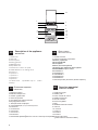
1 Hob burner
2 Hob Grid
3.Control panel
4.Sliding grill rack
5.DRIPPING pan
6.Adjustable foot
7.Containment surface for spills
8.GUIDE RAILS for the sliding racks
9.position 5
10.position 4
11.position 3
12.position 2
13.position 1
14. Glass Cover *(Available only on certain
models)
Description of the appliance
Overall view
GB
1 Газовые горелки
2 Рабочая поверхность
3 Панель управления
4 Решетка духовки
5 Противень или жарочный лист
6 Регулируемые ножки
7 Электрические конфорки
8
HAПPABЛЯЮЩИE для противеней решеток
9 Положение 1
10 Положение 2
11 Положение 3
12 Положение 4
13 Положение 5
14 Cтеклянная крышка (Имеется только в некоторых моделях.)
Описание изделия
Общий вид
UA
Опис плити
Загальнии вигляд
1. Газовий пальник
2. Піддон на випадок переливань
3.Панель управління
4.Полка РЕШІТKИ
5.Полка ДEКО
6.Лапка для налаштування
7.Пoверхня для збирання збiглoї piдини
8.HAПPABЛЯЮЧІ для полиць
9.положення 5
10.положення 4
11.положення 3
12.положення 2
13.положення 1
14.Скляна кришка (Є лише в деяких моделях.)
RS
1.Arzătoare pe gaz
2.Grătare plită
3.Panou frontal de control
4.Grătarul cuptorului
5.Tavă de coacere
6.Picioare reglabile
7.Plită
8.GHIDAJE alunecare rafturi
9.nivelul 5
10. nivelul 5
11.nivelul 5
12.nivelul 5
13.nivelul 5
14.Capacul din sticlă
(prezent doar la anumite modele)
Descriere aparatului
Vedere de ansamblu
RO
1
2
3
4
5
6
7
8
9
10
11
12
13
6
14

3
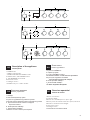
Description of the appliance
Control panel
GB
1.TIMER knob*
2.GRILL indicator light
3.OVEN AND GRILL CONTROL knob
4.OVEN LIGHT / ROTISSERIE button
5. Hob BURNER control knob
6.Electronic timer*
7 Analogue Timer*
*Available only on certain models
Описание изделия
Панель управления
UA
Опис плити
Панель управління
RS
1.Таймер*
2.Световой индикатор
гриль
3.Рукоятка управления духовкой и грилем
4.Кнопка включения/выключения освещения духовки
5. Рукоятки включения газовых конфорок
варочной панели
6. Электронный таймер *
7. Аналоговый таймер*
*Имеется только в некоторых моделях
1.Сукоятка ТАЙМЕРА*
2. Індикатор
гриль
3. Ручка ДУХОВКА й гриля
4.КНОПКА РОЖНА та ОСВІТЛЕННЯ ДУХОВКИ
5.Ручки для керування газовими
пальниками на варильній поверхні
6. Електронний таймер *
7. Аналоговий таймер*
*Є лише в деяких моделях
Descriere aparatului
Panoul de control
RO
1.Buton cronometru*
2.Indicator GRILL
3.Buton de comandã pentru cuptor i grill
4.Buton pentru activarea luminii din cuptor/ rotisserie
5.Butoane comandi ochiuri aragaz
6. Electronic Timer *
7 Analogic Timer*
*Prezent doar la anumite modele
J
2
3
4
56
2
3
4
51
2
3
4
57

4
GB
! Before operating your new appliance please read
this instruction booklet carefully. It contains important
information concerning the safe installation and
operation of the appliance.
! Please keep these operating instructions for future
reference. Make sure that the instructions are kept with
the appliance if it is sold, given away or moved.
! The appliance must be installed by a qualified
professional according to the instructions provided.
! Any necessary adjustment or maintenance must be
performed after the cooker has been disconnected
from the electricity supply.
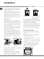
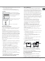
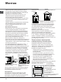
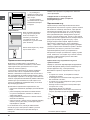
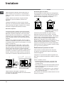
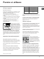
Room ventilation
The appliance may only be installed in permanently-
ventilated rooms, according to current national
legislation. The room in which the appliance is installed
must be ventilated adequately so as to provide as
much air as is needed by the normal gas combustion
process (the flow of air must not be lower than 2 m
3
/h
per kW of installed power).
The air inlets, protected by grilles, should have a duct
with an inner cross section of at least 100 cm
2
and
should be positioned so that they are not liable to even
partial obstruction (see gure A).
These inlets should be enlarged by 100% - with a
minimum of 200 cm
2
- whenever the surface of the
hob is not equipped with a flame failure safety device.
When the flow of air is provided in an indirect manner
from adjacent rooms (see gure B), provided that these
are not communal parts of a building, areas with
increased fire hazards or bedrooms, the inlets should
be fitted with a ventilation duct leading outside as
described above.
Adjacent room Room
requiring
ventilation
Disposing of combustion fumes
The disposal of combustion fumes should be
guaranteed using a hood connected to a safe and
efficient natural suction chimney, or using an electric
fan that begins to operate automatically every time the
appliance is switched on (see gure).
Installation
A
A B
! After prolonged use of the appliance, it is advisable to
open a window or increase the speed of any fans used.
! The liquefied petroleum gases are heavier than air
and collect by the floor, therefore all rooms containing
LPG cylinders must have openings leading outside so
that any leaked gas can escape easily.
LPG cylinders, therefore, whether partially or
completely full, must not be installed or stored in rooms
or storage areas that are below ground level (cellars,
etc.). Only the cylinder being used should be stored
in the room; this should also be kept well away from
sources of heat (ovens, chimneys, stoves) that may
cause the temperature of the cylinder to rise above
50°C.
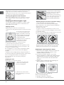
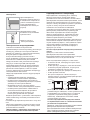
Positioning and levelling
! It is possible to install the appliance alongside
cupboards whose height does not exceed that of the
hob surface.
! Make sure that the wall in contact with the back of
the appliance is made from a non-flammable, heat-
resistant material (T 90°C).
To install the appliance correctly:
• Place it in the kitchen, dining room or the bed-sit (not
in the bathroom).
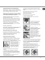
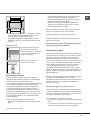
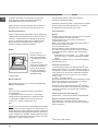
• If the top of the hob is higher than the cupboards,
the appliance must be installed at least 600 mm away
from them.
• If the cooker is installed underneath a wall cabinet,
there must be a minimum distance of 420 mm
between this cabinet and the top of the hob.
This distance should be increased to 700 mm if the
wall cabinets are flammable (see gure).
Ventilation opening
for comburent air
Increase in the gap
between the door and
the flooring
Fumes channelled
straight outside
Fumes channelled through
a chimney or a branched
flue system (reserved for
cooking appliances)
HOOD
420
Min.
min.
650
mm. with hood
min.
700
mm. without hood
mm.
600
Min. mm.
420
Min. mm.

GB
5
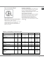
Levelling
If it is necessary to level the
appliance, screw the adjustable
feet into the places provided on
each corner of the base of the
cooker (see gure).
The legs* fit into the slots on the
underside of the base of the
cooker.
Electrical connection
Install a standardised plug corresponding to the load
indicated on the appliance data plate (see Technical
data table).
The appliance must be directly connected to the mains
using an omnipolar circuit-breaker with a minimum contact
opening of 3 mm installed between the appliance and the
mains. The circuit-breaker must be suitable for the charge
indicated and must comply with current national legislation
(the earthing wire must not be interrupted by the circuit-
breaker). The supply cable must be positioned so that it
does not come into contact with temperatures higher than
50°C at any point.
Before connecting the appliance to the power supply,
make sure that:
• The appliance is earthed and the plug is compliant with
the law.
• The socket can withstand the maximum power of the
appliance, which is indicated by the data plate.
• The voltage is in the range between the values
indicated on the data plate.
• The socket is compatible with the plug of the
appliance. If the socket is incompatible with the
plug, ask an authorised technician to replace it. Do
not use extension cords or multiple sockets.
! Once the appliance has been installed, the power
supply cable and the electrical socket must be easily
accessible.
! The cable must not be bent or compressed.
! The cable must be checked regularly and replaced
by authorised technicians only.
! The manufacturer declines any liability should
these safety measures not be observed.
Gas connection
Connection to the gas network or to the gas cylinder
may be carried out using a flexible rubber or steel hose,
in accordance with current national legislation and after
making sure that the appliance is suited to the type of gas
with which it will be supplied (see the rating sticker on
the cover: if this is not the case see below). When using
liquid gas from a cylinder, install a pressure regulator
which complies with current national regulations. To
make connection easier, the gas supply may be turned
sideways*: reverse the position of the hose holder with
that of the cap and replace the gasket that is supplied
with the appliance.
! Check that the pressure of the gas supply is
consistent with the values indicated in the Table
of burner and nozzle specifications (see below).
This will ensure the safe operation and durability of
your appliance while maintaining efficient energy
consumption.
Gas connection using a flexible rubber hose
Make sure that the hose complies with current national
legislation. The internal diameter of the hose must
measure: 8 mm for liquid gas supply; 13 mm for
methane gas supply.
Once the connection has been performed, make sure
that the hose:
• Does not come into contact with any parts that reach
temperatures of over 50°C.
• Is not subject to any pulling or twisting forces and
that it is not kinked or bent.
• Does not come into contact with blades, sharp
corners or moving parts and that it is not
compressed.
* Only in certain models
• Is easy to inspect along its whole length so that its
condition may be checked.
• Is shorter than 1500 mm.
• Fits firmly into place at both ends, where it will
be fixed using clamps that comply with current
regulations.
! If one or more of these conditions is not fulfilled
or if the cooker must be installed according to the
conditions listed for class 2 - subclass 1 appliances
(installed between two cupboards), the flexible steel
hose must be used instead (see below
Connecting a flexible jointless stainless steel pipe
to a threaded attachment
Make sure that the hose and gaskets comply with
current national legislation.
To begin using the hose, remove the hose holder on
the appliance (the gas supply inlet on the appliance is
a cylindrical threaded 1/2 gas male attachment).
• Do not position blinds behind the cooker or less than
200 mm away from its sides.
• Any hoods must be installed according to the
instructions listed in the relevant operating manual.

6
GB
! Perform the connection in such a way that the hose
length does not exceed a maximum of 2 metres,
making sure that the hose is not compressed and does
not come into contact with moving parts.
Checking the tightness of the connection
When the installation process is complete, check the
hose fittings for leaks using a soapy solution. Never
use a flame.
Adapting to different types of gas
It is possible to adapt the appliance to a type of gas
other than the default type (this is indicated on the
rating label on the cover).
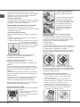
Adapting the hob
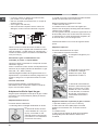
Replacing the nozzles for the hob burners:
1. Remove the hob grids and slide the burners off their
seats.
2. Unscrew the nozzles using
a 7 mm socket spanner (see
gure), and replace them with
nozzles suited to the new type
of gas (see Burner and nozzle
speci cations table).
3. Replace all the components
by following the above
instructions in reverse.
Adjusting the hob burners’ minimum setting:
1. Turn the tap to the minimum position.
2. Remove the knob and adjust the regulatory screw,
which is positioned inside or next to the tap pin, until
the flame is small but steady.
! If the appliance is connected to a liquid gas supply,
the regulatory screw must be fastened as tightly as
possible.
3. While the burner is alight, quickly change the position of
the knob from minimum to maximum and vice versa several
times, checking that the flame is not extinguished.
! The hob burners do not require primary air
adjustment.
Adapting the oven
Replacing the oven burner nozzle:
1. Open the oven door fully
2. Pull out the sliding oven
bottom (see diagram).
3. Remove the oven burner
after unscrewing the screws V
(see gure).
4. Unscrew the nozzle using a
special nozzle socket spanner
(see gure) or with a 7 mm
socket spanner, and replace it
with a new nozzle that is suited
to the new type of gas (see
Burner and nozzle speci cations
Adjusting the gas oven burner’s minimum setting:
1. Light the burner (see Start-up and Use).
2. Turn the knob to the minimum position (MIN)
after it has been in the maximum position (MAX) for
approximately 10 minutes.
3. Remove the knob.
4. Tighten or loosen the adjustment screws on the
outside of the thermostat pin (see gure) until the flame
is small but steady.
! In the case of natural gas, the adjustment screw must
be unscrewed by turning it anti-clockwise.
V
5. Turn the knob from the MAX position to the MIN
position quickly or open and shut the oven door,
making sure that the burner is not extinguished.
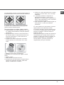
Replacing the Triple ring burner nozzles
1. Remove the pan supports and lift the burners out
of their housing. The burner consists of two
separate parts (see pictures).
2. Unscrew the nozzles using a 7 mm socket
spanner. Replace the nozzles with models that are
configured for use with the new type of gas (see
Table 1). The two nozzles have the same hole
diameter.
3. Replace all the components by completing the
above operations in reverse order.
• Adjusting the burners’ primary air :
Does not require adjusting.
• Setting the burners to minimum:
1. Turn the tap to the low flame position.

GB
7
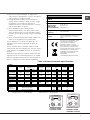
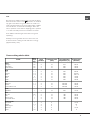
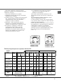
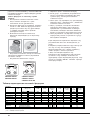
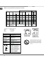
Table of burner and nozzle specifications
CG65SG5 UA/HA
CG65SG1 UA/HA
CG65SG3 X UA /HA
CG64SG1 UA/HA
CG64SG3 UA/HA
S
S
R
A
Table 1 Liquid Gas Natural Gas
Diameter
(mm)
Thermal Power
kW (p.c.s.*)
By Pass
1/100
Nozzle
1/100
Flow*
g/h
Nozzle
1/100
Flow*
l/h
Burner
Nominal Reduced (mm) (mm) *** ** (mm)
Fast
(Large)(R)
100 3.00 0.7 41 86 218 214 116 286
Semi Fast
(Medium)(S)
75 1.90 0.4 30 70 138 136 106 181
Auxiliary
(Small)(A)
55 1.00 0.4 30 50 73 71 79 95
Tripple Ring
(TC)
Oven - 2.60 1.0 52 78 189 186 119 248
Supply
Pressures
Nominal (mbar)
Minimum (mbar)
Maximum (mbar)
28-30
20
35
37
25
45
20
17
25
* At 15°C 1013 mbar-dry gas *** Butane P.C.S. = 49,47 MJ/Kg
** Propane P.C.S. = 50,37 MJ/Kg Natural P.C.S. = 37,78 MJ/m³
TECHNICAL DATA
Oven Dimensions
HxWxD
31x43,5x43,5 cm
Volume
58 l
Useful
measurements
relating to the
oven compartment
width 46 cm
depth 42 cm
height 8,5 cm
Voltage and
frequency
see data plate
Burners
may be adapted for use with any
type of gas shown on the data
plate.
EC Directives 2006/95/EC dated
12/12/06 (Low Voltage) and
subsequent amendments -
04/108/EC dated 15/12/04
(Electromagnetic Compatibility)
and subsequent amendments -
2009/142/EC dated 30/11/09 (Gas)
and subsequent amendments -
90/68/EEC dated 22/07/93 and
subsequent amendments. -
2002/96/EC.
1275/2008(Stand-by/Off-mode)
3. Having adjusted the flame to the required low
setting, while the burner is alight, quickly change
the position of the knob from minimum to
maximum and vice versa several times, checking
that the flame does not go out.
4. Some appliances have a safety device
(thermocouple) fitted. If the device fails to work
when the burners are set to the low flame setting,
increase this low flame setting using the adjusting
screw.
5. Once the adjustment has been made, replace the
seals on the by-passes using sealing wax
! If the appliance is connected to liquid gas, the
regulation screw must be fastened as tightly as
possible.
! Once this procedure is finished, replace the old
rating sticker with one indicating the new type of gas
used. Stickers are available from any of our Service
Centres.
! Should the gas pressure used be different (or vary
slightly) from the recommended pressure, a suitable
pressure regulator must be fitted to the inlet pipe (in
order to comply with current national regulations).
130 3.25 1,5 63 2x65 236 232 2x99 309
S
R
TC A
2. Remove the knob and adjust the adjustment
screw, which is positioned in or next to the tap pin,
until the flame is small but steady.

8
GB
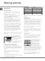
Using the hob
Lighting the burners
For each BURNER knob there is a complete ring
showing the strength of the flame for the relevant
burner.
To light one of the burners on the hob:
1. Bring a flame or gas lighter close to the burner.
2. Press the BURNER knob and turn it in an
anticlockwise direction so that it is pointing to the
maximum flame setting .
3. Adjust the intensity of the flame to the desired level
by turning the BURNER knob in an anticlockwise
direction. This may be the minimum setting , the
maximum setting or any position in between the two.
Several models are equipped with an ignition device
which is built into the knob; in this case the electronic
ignition device* is present (C) but the ignition button
is not. Simply press the BURNER knob and turn it
in an anticlockwise direction so that it is pointing
to the maximum flame setting, until the burner is lit.
The burner may be extinguished when the knob is
released. If this occurs, repeat the operation, holding
the knob down for a longer period of time.
! If the flame is accidentally extinguished, switch off the
burner and wait for at least 1 minute before attempting
to relight it.
If the appliance is equipped with a flame failure safety
device (X)*, press and hold the BURNER knob for
approximately 2-3 seconds to
keep the flame alight and to
activate the device.
To switch the burner off, turn
the knob until it reaches the
stop position
•.
Practical advice on using the burners
For the burners to work in the most efficient way
possible and to save on the amount of gas consumed, it
is recommended that only pans that have a lid and a flat
base are used. They should also be suited to the size of
the burner.
To identify the type of burner, please refer to the
diagrams contained in the “Burner and nozzle
specifications”.
! On the models supplied with a reducer shelf,
remember that this should be used only for the auxiliary
Start-up and use
burner when you use casserole dishes with a diameter
under 12 cm.
Using the oven
! The first time you use your appliance, heat the empty
oven with its door closed at its maximum temperature
for at least half an hour. Ensure that the room is well
ventilated before switching the oven off and opening
the oven door. The appliance may emit a slightly
unpleasant odour caused by protective substances
used during the manufacturing process burning away.
! Before operating the product, remove all plastic film
from the sides of the appliance.
! Never put objects directly on the bottom of the oven;
this will avoid the enamel coating being damaged.
Only use position 1 in the oven when cooking with the
rotisserie spit.
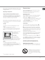
Lighting the oven
To light the oven burner, bring a flame or gas lighter
close to opening F (see gure) and press the OVEN
control knob while turning it in an anticlockwise
direction until it reaches the MAX position.
If the appliance is fitted with
an electronic lighting device*,
press the ignition button,
marked with the symbol
, then hold the OVEN
control knob and turn it in
an anticlockwise direction,
towards the MAX position, until
the burner is lit. If, after 15 seconds, the burner is still
not alight, release the knob, open the oven door and
wait for at least 1 minute before trying to light it again.
If there is no electricity the burner may be lit using a
flame or a lighter, as described above.
! The oven is fitted with a safety device and it is
therefore necessary to hold the OVEN control knob
down for approximately 6 seconds.
* Only available in certain models.
F
X
C
Burner ř Cookware Diameter (cm)
Fast (R) 24 - 26
Semi Fast (S) 16 - 20
Auxiliary (A) 10 - 14
Triple Crown (TC) 24 - 26

GB
9
*
Only available in certain models.
! If the flame is accidentally extinguished, switch off the
burner and wait for at least 1 minute before attempting
to relight the oven.
Adjusting the temperature
To set the desired cooking temperature, turn the
OVEN control knob in an anticlockwise direction.
Temperatures are displayed on the control panel and
may vary between MIN (150°C) and MAX (250°C).
Once the set temperature has been reached, the oven
will keep it constant by using its thermostat.
! If the flame is accidentally extinguished, switch off the
burner and wait for at least 1 minute before attempting
to relight the grill.
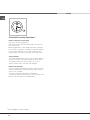
Turnspit
To operate the rotisserie (see diagram) proceed as
follows:
1. Place the dripping pan in position 1.
2. Place the rotisserie support in position 4 and insert
the spit in the hole provided on the back panel of the
oven.
3. Acitvate the function
by pressing the
TURNSPIT button.
Oven light
The light may be
switched on at any
moment by pressing the
OVEN LIGHT button.
Timer*
To activate the Timer proceed as follows:
1. Turn the TIMER knob in a clockwise direction for
almost one complete revolution to set the buzzer.
2. Turn the TIMER knob in an anticlockwise direction
to set the desired length of time.
Electronic timer*
This function displays the time and works as a timer
which counts down to zero.
! All functions will be implemented approximately 7
seconds after they have been set.
Resetting the clock
After the appliance has been connected to the power
supply, or after a power cut, the clock display will
begin to blink, showing the figure: 0:00
• Press button
and then buttons
-
and
+
to set the
exact time. Press and hold the buttons to quicken
the count upwards.
Any necessary modifications can be made by
repeating the above process.
Timer feature
This function may be accessed by pressing the
button, after which the display will show the symbol
. Every time the
+
button is pressed it corresponds
to a time increase of 10 seconds, until it reaches 99
minutes and 50 seconds. After this point, each press of
the button represents an increase of one minute, up to
a maximum of 10 hours.
Pressing the
-
button reduces the time.
After the time period has been set, the timer will begin
to count down. When the timer reaches zero, the
buzzer will sound (this may be stopped by pressing
any button).
The time may be displayed by pressing the
button,
and the
symbol indicates that the timer function has
been set. After approximately 7 seconds, the display
will automatically revert to the timer.
Cancelling a time that has already been set
Press the
–
button until the display shows 0:00.
Adjusting the buzzer volume
After selecting and confirming the clock settings, use
the – button to adjust the volume of the alarm buzzer.
WARNING! The glass lid can break in if
it is heated up. Turn off all the burners
and the electric plates before closing
the lid. *Applies to the models with glass
cover only.

10
GB
*
Only available in certain models.
Clock with Country Style timer *
How to reset the correct time
The oven must be plugged in.
Pull the knob and turn it anticlockwise until you set
the correct time.
! !
! !
! The programmer is electrically powered, therefore
in the event of a power shortage, it will stop working
for the entire duration of the same. Following this
power failure, the correct time will have to be reset.
Timer Feature
The timer feature allows you to enter a given amount
of time from which the timer begins to count down.
This feature does not turn the oven on or off; it
merely sounds when the time has elapsed.
How to set the timer
Turn the knob anticlockwise until the marker lines up
with the desired time (internal scale), which can be
seen in the “window”.
The time countdown will begin immediately.
To interrupt the timer buzzer, or to use only the clock
feature, set the marker to the ! symbol

GB
11
Oven cooking advice table
Grill
By turning the OVEN control knob in an anticlockwise
direction until it reaches the
position, the infrared
ray grill is activated. The grill enables the surface of
food to be browned evenly and is particularly suitable
for roast dishes, schnitzel and sausages. Place the
rack in position 4 or 5 and the dripping pan in position
1 to collect fat and prevent the formation of smoke.
! The GRILL indicator light shows when the grill is
operating.
! Always use the grill with the oven door shut; this
achieves better cooking results and saves energy
(approximately 10%).
Foods
Weig-
ht (in
kg)
Rack
position
Preheating time
(min)
Recommended
temperature (°C)
Cooking time
(minutes)
Pasta
Lasagne
Cannelloni
Gratin dishes
2.5
2.5
2.5
3
3
3
10
10
10
210
200
200
60-75
40-50
40-50
Meat
Veal
Chicken
Duck
Rabbit
Pork
Lamb
1.7
1.5
1.8
2
2.1
1.8
3
3
3
3
3
3
10
10
10
10
10
10
200
220
200
200
200
200
85-90
90-100
100-110
70-80
70-80
90-95
Fish
Mackerel
Dentex
Trout baked in foil
1.1
1.5
1
3
3
3
10
10
10
180-200
180-200
180-200
35-40
40-50
40-45
Pizza
Napolitan
1 3 15 220 15-20
Pies
Biscuits
Tart
Savoury pies
Leavened cakes
0.5
1.1
1
1
3
3
3
3
15
15
15
15
180
180
180
180
30-35
30-35
45-50
35-40
Grilled foods
Veal steak
Cutlets
Hamburgers
Mackerel
Toast
1
1.5
1
1
n.4
4
4
3
4
4
5
5
5
5
5
15-20
20
7
15-20
5

12
GB
Precautions and tips
! This appliance has been designed and manufactured
in compliance with international safety standards.
The following warnings are provided for safety reasons
and must be read carefully.
General safety
• The appliance was designed for domestic use inside
the home and is not intended for commercial or
industrial use.
• The appliance must not be installed outdoors, even in
covered areas. It is extremely dangerous to leave the
appliance exposed to rain and storms.
• Do not touch the appliance with bare feet or with wet
or damp hands and feet.
• The appliance must be used by adults only for
the preparation of food, in accordance with the
instructions outlined in this booklet. Any other
use of the appliance (e.g. for heating the room)
constitutes improper use and is dangerous.
The manufacturer may not be held liable for any
damage resulting from improper, incorrect and
unreasonable use of the appliance.
• The instruction booklet accompanies a class 1
(insulated) or class 2 - subclass 1 (recessed
between 2 cupboards) appliance.
• When the appliance is in use, the heating
elements and some parts of the oven door
become extremely hot. Make sure you don’t
touch them and keep children well away.
• Make sure that the power supply cables of other
electrical appliances do not come into contact with
the hot parts of the oven.
• The openings used for the ventilation and dispersion
of heat must never be covered.
• Do not close the glass hob cover (selected models
only) when the burners are alight or when they are
still hot.
• Always use oven gloves when placing cookware in
the oven or when removing it.
• Do not use flammable liquids (alcohol, petrol, etc...)
near the appliance while it is in use.
• Do not place flammable material in the lower storage
compartment or in the oven itself. If the appliance is
switched on accidentally, it could catch fire.
• The internal surfaces of the compartment (where
present) may become hot.
• Always make sure the knobs are in the
•
position
and that the gas tap is closed when the appliance is
not in use.
• When unplugging the appliance, always pull the plug
from the mains socket; do not pull on the cable.
• Never perform any cleaning or maintenance work
without having disconnected the appliance from the
electricity mains.
• If the appliance breaks down, under no
circumstances should you attempt to repair
the appliance yourself. Repairs carried out by
inexperienced persons may cause injury or further
malfunctioning of the appliance. Contact Assistance.
• Do not rest heavy objects on the open oven door.
• Do not let children play with the appliance.
• The appliance should not be operated by people
(including children) with reduced physical, sensory
or mental capacities, by inexperienced individuals
or by anyone who is not familiar with the product.
These individuals should, at the very least, be
supervised by someone who assumes responsibility
for their safety or receive preliminary instructions
relating to the operation of the appliance.
Disposal
• When disposing of packaging material: observe local
legislation so that the packaging may be reused.
• The European Directive 2002/96/EC on Waste
Electrical and Electronic Equipment (WEEE),
requires that old household electrical appliances
must not be disposed of in the normal unsorted
municipal waste stream. Old appliances must
be collected separately in order to optimise the
recovery and recycling of the materials they contain
and reduce the impact on human health and the
environment. The crossed out “wheeled bin” symbol
on the product reminds you of your obligation,
that when you dispose of the appliance it must be
separately collected.
Consumers should contact their local authority
or retailer for information concerning the correct
disposal of their old appliance.
Respecting and conserving the
environment
• You can help to reduce the peak load of the
electricity supply network companies by using the
oven in the hours between late afternoon and the
early hours of the morning.
• Always keep the oven door closed when using the
GRILL mode This will achieve better results while
saving energy (approximately 10%).
• Check the door seals regularly and wipe them clean
to ensure they are free of debris so that they adhere
properly to the door, thus avoiding heat dispersion.
If the cooker is placed on a pedestal, take the neces-
sary precautions to prevent the cooker from sliding
off the pedestal itself.
•

GB
13
Switching the appliance off
Disconnect your appliance from the electricity supply
before carrying out any work on it.
Cleaning the appliance
! Never use steam cleaners or pressure cleaners on
the appliance.
• The stainless steel or enamel-coated external parts
and the rubber seals may be cleaned using a
sponge that has been soaked in lukewarm water
and neutral soap. Use specialised products for the
removal of stubborn stains. After cleaning, rinse well
and dry thoroughly. Do not use abrasive powders or
corrosive substances.
• The hob grids, burner caps, flame spreader rings
and burners may be removed to make cleaning
easier; wash them in hot water and non-abrasive
detergent, making sure all burnt-on residue is
removed before drying them thoroughly.
• Clean the terminal part of the flame failure safety
devices* frequently.
• The inside of the oven should ideally be cleaned
after each use, while it is still lukewarm. Use hot
water and detergent, then rinse well and dry with a
soft cloth. Do not use abrasive products.
•
Clean the glass part of the oven door using a
sponge and a non-abrasive cleaning product, then
dry thoroughly with a soft cloth. Do not use rough
abrasive material or sharp metal scrapers as these
could scratch the surface and cause the glass to
crack.
• The accessories can be washed like everyday
crockery, and are even dishwasher safe.
• Do not close the cover when the burners are alight
or when they are still hot.
Inspecting the oven seals
Check the door seals around the oven regularly. If
the seals are damaged, please contact your nearest
Authorised After-sales Service Centre. We recommend
that the oven is not used until the seals have been
replaced.
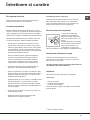
Replacing the oven light bulb
1. After disconnecting the
oven from the electricity mains,
remove the glass lid covering
the lamp socket (see gure).
2. Remove the light bulb and
replace it with a similar one:
voltage 230 V, wattage 25 W,
cap E 14.
3. Replace the lid and reconnect the oven to the
electricity supply.
Gas tap maintenance
Over time, the taps may become jammed or difficult to
turn. If this happens, the tap must be replaced.
! This procedure must be performed by a qualified
technician authorised by the manufacturer.
Assistance
! Never use the services of an unauthorised technician.
Please have the following information to hand:
• The type of problem encountered.
• The appliance model (Mod.).
• The serial number (S/N).
The latter two pieces of information can be found on
the data plate located on the appliance.
Care and maintenance
* Only available in certain models.

14
RS
! Важно сохранить данное руководство для его
последующих консультаций. В случае продажи,
передачи или переезда проверьте, чтобы данное
руководство сопровождало изделие.
! Внимательно прочитайте инструкции: в них
содержатся важные сведения об установке,
эксплуатации и безопасности изделия.
! Установка изделия производится в соответствии
с данными инструкциями квалифицированными
специалистами.
! Любая операция по
регуляции или техническому
обслуживанию должна производиться только
после отсоединения кухонной плиты от сети
электропитания.
Вентиляция помещений
Изделие может быть установлено в помещениях
с постоянной вентиляцией в соответствии с
действующими национальными нормативами. В
помещении, в котором устанавливается изделие,
должен быть обеспечен приток воздуха в объеме,
необходимом для оптимального горения газа
(расход
воздуха не должен быть меньше 2 м<+>3/
час на 1 кВт установленной мощности).
Вентиляционные отверстия, защищенные
решетками, должны иметь воздуховод площадью не
менее 100 мм
2
полезного сечения и распологаться
таким образом, чтобы их нельзя было закрыть, даже
частично (см. рисунок А).
Эти отверстия должны быть увеличины на 100% - то
есть иметь минимальную площадь 200 см
2
- если
варочная панель не оснащена предохранительным
устройством отсутствия пламени, и если воздух
в помещение поступает из смежных помещений
(см. рисунок В), которые не должны быть общими
зонами дома, пожароопасными помещениями
или спальнями, оснащенных вентиляционным
воздуховодом, выходящим на улицу, как описано
выше.
! После продолжительного использования изделия
рекомендуется открыть окно или
включить более
интенсивный режим вентиляторов.
Дымоудаление
Дымоудаление должно осуществляться через
вытяжной зонт, соединенный с эффективным
дымоходом с натуральной тягой, или посредством
электровентилятора, который автоматически
включается каждый раз при включении изделия (см.
рисунок).
! Сжиженные натуральные газы тяжелее воздуха,
застиваются внизу, по этой причине помещения
для хранения баллонов с СПГ должны иметь
внетиляционные отверстия у пола для вентиляции
возможных утечек газа.
Баллоны с СПГ, полные или частично
израсходованные, не дожны размещаться или
храниться в помещениях или хранилищах,
расположенных в подземных помещениях (подвалы,
и т.д.). Храните в помещении только рабочий
баллон, установив его вдали от источников тепла
(духовок, каминов, печей), которые могут
нагреть его
до температуры выше 50°C.
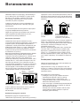
Расположение и нивелировка
! Изделие может быть установлено рядом с
кухонными элементами, высота которых не
превышает
поверхность
варочной
панели
.
! Проверьте, чтобы стена, к которой прилегает
задняя часть изделия, была из невозгораемого
материала и устойчивой к теплу (Т 90°C).
Правильный порядок монтажа:
• изделие может быть установлено на кухне, в
столовой или в однокомнатной квартире (
не в
ванной комнате);
• если варочная панель кухонной плиты выше
кухонных элементов, необходимо отодвинуть их
от плиты на расстояние не менее 600 мм.
• если кухонная плита устанавливается под
навесным кухонным шкафом, он должен
располагаться на высоте не менее 420 мм от
поверхности варочной панели.
Это расстояние должно быть 700 мм, если навесные
кухонные
шкафы выполнены из возгораемого
материала (см
.
рисунок);
Монтаж
A
Смежное
помещение
Вентилируемое
помещение
Вентиляционные
отверстия для притока
воздуха
Увеличение
зазора
между
дверью и полом
A
B
Прямой отвод
Дымоудаление через камин или дымоход
с медным покрытием (для кухонных
устройств для приготовления пищи)
HOOD
420
Min.
min.
650
mm. with hood
min.
700
mm. without hood
mm.
600
Min. mm.
420
Min. mm.
• не заправляйте
занавески за кухонную
плиту и
не приближайте
их на расстояние
меньше 200 мм.
• возможная кухонная
вытяжка должна
быть установлена в
соответствии
с
инструкциями,
приведенными в
техническом руководстве к
вытяжке
.

RS
15
*Имеется только в
некоторых моделях
• сетевая розетка должна быть рассчитана на
максимальную потребляемую мощность изделия,
указанную на паспортной табличке;
• напряжение и частота тока сети должны
соответствовать электрическим данным изделия;
• сетевая розетка должна быть совместима со
штепсельной вилкой изделия. В противном
случае замените розетку или вилку; не
используйте
удлинители
или
тройники
.
! Изделие должно быть установлено таким образом,
чтобы сетевой шнур и сетевая розетка были легко
доступны
.
! Сетевой шнур изделия не должен быть согнут или
сжат
.
! Регулярно проверяйте состояние сетевого шнура
и при необходимости поручайте его замену только
уполномоченным техникам.
! Фирма снимает с себя всякую ответственность в
случае
несоблюдения
вышеописанных
правил.
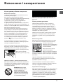
Подсоединение к газопроводу
Подсоединение к газопроводу или к газовому
баллону выполняется посредством гибкого
резинового или стального шланга в соответствии с
действующими национальными нормативами, после
проверки настройки изделия на тип используемого
газа (см. этикетку настройки на крышке: в противном
случае см. ниже). В случае использования
сжиженного газа из баллона необходимо
установить регуляторы давления, соответствующие
действующему
национальному нормативу. Для
облегчения подсоединения газовый патрубок
является ориентируемым*: поменяйте местами
крепежную блокировочную гайку на заглушку и
замените прилагающееся уплотнение.
! Для надежного функционирования, рационального
использования энергии и более длительного срока
службы изделия проверьте, чтобы давление подачи
газа соответствовало значениям, указанным в
таблице «Характеристики газовых конфорок и
форсунок» (см. ниже).
Газовое подсоединение посредством резинового
шланга
Проверьте, чтобы шланг соответствовал
действующим национальным нормативам.
Внутренний диаметр шланга должен быть: 8 мм для
сжижженного газа; 13 см для газа метана.
После подсоединения проверьте, чтобы шланг:
Электрическое
подсоединение
Установите на кабель электропитания
нормализованную штепсельную вилку, расчитанную
на нагрузку, указанную на паспортной табличке
изделия (см. табличку с техническими данными).
В случае прямого подключения к сети
электропитания между кухонной плитой и
сетью необходимо установить мультиполярный
выключатель с минимальным расстоянием
между контактами 3 мм, расчитанный на данную
нагрузку и соответствующий действующим
нормативам (
выключатель не должен размыкать
провод заземления). Сетевой шнур должен быть
расположен таким образом, чтобы ни в одной
точке его температура не превышала температуру
помещения более чем на 50°C.
Перед подсоединением сетевого шнура проверьте
следующее:
• сетевая розетка должна быть соединена с
заземлением и соответствовать
нормативам
;
Нивелировка
При необходимости
выровнять изделие вкрутите
в специальные отверстия по
углам в основании кухонной
плиты прилагающиеся
нивелировочные ножки (см.
рисунок).
Прилагающиеся ножки*
вставляются под основание
кухонной плиты.
• не касался частей, температура которых может
превысить 50°C;
• не был растянут,
перекручен, сжат или заломлен;
• не касался режущих предметов, острых углов,
подвижных предметов и не был сжат;
• был легко доступен для проверки по всей длине;
• не был длиннее 1500 мм;
• был прочно закреплен с обоих концов при
помощи хомутов, соответствующих действующим
национальным нормативам.
! Если одно или несколько из вышеописанных
условий
не будет соблюдено, и если кухонная плита
устанавливается в условиях класса 2, подгруппа
1 (изделие, встроенное между двух кухонных
элементов), необходимо использовать гибкий
стальной шланг (см. ниже).
Газовое подсоединение посредством шланга
из нержавеющей стали со сплошной оплеткой с
резьбовыми соединениями.
Проверьте, чтобы шланг и уплотнения соответствовали
действующим национальным нормативам.
Для подсоединения
шланга снимите блокировочную
гайку с изделия (патрубок подачи газа в изделие
имеет цилиндрическу резьбу Ѕ газ «папа»).
Крепление
шланга
Точка соединения
Точка соединения
Изолирующая
заглушка
Изолирующая
заглушка
Крепление
шланга
ГОРЯЧАЯ ПОВЕРХНОСТЬ

16
RS
V
3. восстановите на место все комплектующие,
выполняя операции в обратном порядке по
отношению к описанным выше.
Порядок регуляции минимального пламени
конфорок на варочной панели:
1. поверните рукоятку в положение минимального
пламени;
2. снимите рукоятку и поверните регуляционный
винт, расположенный внутри или рядом со стержнем
крана, вплоть до получения стабильного малого
пламени.
!
В случае использования сжиженного природного
газа винт регуляции должен быть отвинчен против
часовой стрелки;
3. проверьте, чтобы конфорка не гасла при резком
повороте крана из положения максимального
пламени в положение минимального пламени.
! Конфорки варочной панели не нуждаются в какой-
либо регуляции первичного воздуха.
Настройка духового шкафа
Порядок замены форсунки газовой горелки
духового
шкафа:
1. полностью откройте дверцу
духового шкафа;
2. выньте съемное дно духовки
(см. рисунок);
3. отвинтите крепежные винты
горелки и снимите горелку
духового шкафа, сняв винт V;
4. отвинтите форсунку горелки
при помощи специального
полого ключа для форсунок
(см. рисунок) или полого ключа
7 мм и замените форсунку
на новую, расчитанную на
новый тип газа (см. таблицу
Характеристики горелок и
форсунок).
Регуляция минимального пламени горелки
духового
шкафа
:
1. включите горелку (см. Пуск и Эксплуатация);
2. оставьте рукоятку примерно в течение 10 минут в
положении максимального пламени (МАКС), затем
поверните ее в положение минимального
! Длина подсоединяемого шланга не должна
превышать 2 метра при максимальном
растяжении.
Проверьте, чтобы шланг не касался подвижных
деталей, которые могут его сжать.
Проверка
уплотнения
По завершении подсоединения проверьте
прочность
уплотнения всех патрубков при помощи
мыльного
раствора, но никогда не пламенем.
Настройка на различные типы газа
Изделие может быть настроено на тип газа,
отличающийся от оригинального (указан на
этикетке
настройки на крышке).
Настройка варочной панели
Порядок замены форсунок конфорок на варочной
панели:
1. снимите решетки с варочной панели и выньте
горелки из своих гнезд;
2. отвинтите форсунки при помощи полого ключа 7
мм (см. рисунок) и замените
их на
форсунки, расчитанные
на новый тип газа (см.
таблицу
Характеристики горелок и
форсунок);
пламени (МИН);
3. снимите рукоятку;
4. поверните регулировочный винт, расположенный
внутри стержня термостата (см. рисунок), вплоть до
получения малого стабильного пламени.
! В случае использования сжиженного природного
газа винт регуляции должен быть отвинчен против
часовой
стрелки;
5. проверьте, чтобы горелка не гасла при резком
вращении рукоятки-регулятора из положения МАКС
в положение
МИН или при резком открывании или
закрывании дверцы духовки.
Замена форсунок тройной конфорки
1. снимите решетки и выньте горелки из своих
гнезд. Горелка состоит из двух отдельных
частей (см. схемы);
2. отвинтите форсунки полой отверткой 7 мм.
Замените форсунки на новые, пригодные для
нового типа газа (см. таблицу 1). Обе
форсунки имеют одинаковое отверстие.
3. восстановите на место все комплектующие,
выполняя операции в обратном порядке по
отношению к описанным выше.

RS
17
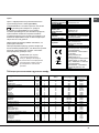
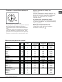
Таблица характеристик горелок и форсунок
* La 15°C єi 1013 мбар – gaz uscat
Пропан 50,37 МДж/Kg
Бутан 49,47 МДж/Kg
Природный газ 37,78 МДж/м
3
CG65SG5 UA/HA
CG65SG1 UA/HA
CG65SG3 X UA /HA
CG64SG1 UA/HA
CG64SG3 UA/HA
S
S
R
A
100 3,00 0,7 41 86 218 214 116 286 143 286
75 1,90 0,4 30 70 138 136 106 181 118 181
55 1,00 0,4 30 50 73 71 79 95 80 95
(TC)
- 2,60 1,0 52 78 189 186 119 248 132 248
28-30
20
35
37
25
45
20
17
25
13
6,5
18
Т
аблица 1
Сжиженный газ
Природный газ
Диаметр
(мм)
Тепловая мощность
кВт (p.c.s.*)
Байпас
1/100
форсунка
1/100
расход*
гр/час
форсунка
1/100
расход*
л/час
форсунка
1/100
расход*
л/час
Горелка
Номинал. Сокращ мм)
(мм)
*** **
(мм)
(мм)
Быстрая
(
Большая)(R)
П
олубыстрая
(
Средняя)(S)
В
спомогательн
а
я Малая А
уховка
Д
авление
п
одачи
Номинальное (мбар)
Минимальное (мбар)
Максимальное (мбар)
Потрiйна
корона
• Регуляция первичного воздуха горелок
Горелки не нуждаются в какой-либо регуляции
первичного воздуха.
• Регуляция минимального пламени
1. Поверните рукоятку-регулятор в положение
минимального пламени;
2. Снимите рукоятку и поверните регуляционный
винт, расположенный внутри или рядом со
стержнем крана, вплоть до получения
стабильного малого пламени.
3. Проверьте, чтобы при резком повороте
рукоятки
из положения максимального
пламени на минимальное, горелки не гасли.
4. В изделиях, оснащенных защитным
устройством (термопарой), в случае
неисправности этого устройства при
минимальном пламени горелок увеличьте
расход газа минимального пламени при
помощи
регуляционного
винта
.
5. По завершении регуляции восстановите
сургучные или подобные пломбы на
обводном газопроводе.
! В случае использования сжиженного газа
регуляционный винт должен быть
завинчен до
упора.
! По завершении операции замените старую
этикетку тарирования на новую,
соответствующую новому типу используемого
газа. Этикетку можно заказать в наших Центрах
Сервисного Обслуживания.
! Если давление используемого газа отличается
(или варьирует) от предусмотренного давления,
необходимо установить на питающем
газопроводе соответствующий регулятор
давления (согласно нормативам EN 88-1 и EN
88-2 «Регуляторы для канализированных
газов
»).
130 3.25 1.5 63
2x65
236 232
2x99
309
2x10⁷
309
S
R
TC A

18
RS
Эксплуатация варочной панели
Включение конфорок
Напротив каждого рукоятки КОНФОРКИ
закрашенным кружком показано положение данной
конфорки на варочной панели.
Порядок включения конфорки на варочной панели:
1. поднесите к конфорке зажженую спичку или
кухонную зажигалку;
2. нажмите и одновременно поверните против
часовой стрелки рукоятку КОНФОРКИ на символ
максимального пламени .
3. отрегулируйте нужную мощность пламени,
поворачивая рукоятку КОНФОРКИ
против часовой
стрелки: на минимум , на максимум или на
среднюю мощность.
ЕНекоторые модели оснащены устроиством
зажигания, встроенным внутри рукоятки. В этом
случае варочная панель оснащена электронным
устроиством зажигания* (см. рисунок), но не кнопкои
зажигания. Нажмите и одновременно поверните
против часовои стрелки рукоятку КОНФОРКИ
на символ максимального пламени
вплоть до
зажигания конфорки. Может случиться, что
конфорка погаснет в момент, когда вы отпустите
рукоятку. В этом случае повторите операцию
зажигания, удерживая рукоятку нажатои подольше.
! В случае внезапного гашения пламени выключите
конфорку и подождите примерно 1 минуту перед ее
повторным включением.
Если изделие оснащено предохранительным
устройством* (X)отсутствия
пламени, держите рукоятку
КОНФОРКИ
нажатой
примерно 2-3 секунды
для того, чтобы пламя
конфорки активировало это
устройство.
Для выключения конфорки
поверните рукоятку вплоть до гашения пламени
•.
Практические советы по эксплуатации газовых
конфорок
Для оптимальной работы конфорок и для экономии
газа следует использовать кухонную посуду с
плоским дном, с диаметром, соответствующим
конфорке, и с крышкой:
Для определения типа конфорки смотрите рисунки в
параграфе «Характеристики конфорок и форсунок».
Включение и эксплуатация
! В моделях, оснащенных дополнительной
решеткой, эта решетка может быть использована
только на вспомогательной конфорке с посудой
диаметром меньше 12 см.
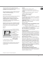
Эксплуатация духового шкафа
! При первом включении духового шкафа
рекомендуем прокалить его примерно в течение 30
минут при максимальной температуре с закрытой
дверцей. Затем выключите духовой шкаф, откройте
дверцу и проветрите помещение. Запах, который вы
можете почувствовать, вызван испарением веществ,
использованных для предохранения духового
шкафа.
! Перед началом эксплуатации необходимо снять
пленку, наклеенную с боков
изделия.
! Никогда не ставьте никаких предметов на дно
духового шкафа, так как они могут повредить
эмалированное покрытие. Используйте положение
1 настройки духового шкафа только для
приготовления на вертеле.
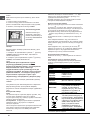
Включение духового шкафа
Для зажигания горелки духового шкафа поднесите
к отверстию F (см. рисунок) зажженную спичку
или кухонную зажигалку, нажмите и одновременно
поверните
против часовой
стрелки рукоятку ДУХОВКИ в
положение МАКС.
Если изделие оснащено
электронной системой
зажигания*, вначале
нажмите кнопку зажигания,
обозначенную символом
, затем нажмите
до упора и одновременно поверните против
часовой стрелки рукоятку КОНФОРКИ на символ
МАКСИМАЛЬНОГО пламени вплоть до зажигания
пламени. Если по прошествии 15 секунд горелка
не загориться, отпустите рукоятку, откройте дверцу
духового шкафа и подождите примерно 1 минуту
перед повторным зажиганием. В случае отсутствия
электропитания можно включить горелку от спички
или
кухонной зажигалки, как было описано выше.
F
*
Имеется только в некоторых моделях
X
C
24 - 26
Ãîðåëêà Äèàìåòð äíà ïîñóäû
(cì)
Áûñòðàÿÿ(R) 24-26
Ïîëóáûñ2ðàÿÿ(S) 16-20
Ä î ï î ë í è 2 å ë ü í à ÿ ÿ( A ) 1 0-1 4
Потрiйна корона ( )ТС

RS
19
* Имеется только в некоторых моделях.
! Когда вы используете гриль, необходимо оставить
дверцу духового шкафа полу-открытой, установив
между дверцей и панелью управления отражатель
D (см. рисунок), препятствующий нагреванию
рукояток.
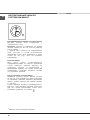
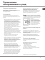
Вертел
Порядок включения
вертела (см. рисунок):
1. установите
противень на 1-ый
уровень;
2. установите
держатель вертела
на 4-ый уровень и
вставьте вертел в
специальное отверстие
в задней
стенке
духового шкафа;
3. включите вертел, нажав на кнопку ВЕРТЕЛ.
Освещение духового шкафа
Освещение духового шкафа может быть включено
в любой момент при выключенной духовке при
помощи кнопки.
! Духовой шкаф оснащен предохранительным
устройством, поэтому необходимо держать рукоятку
ДУХОВКИ нажатой примерно 6 секунд.
! В случае внезапного гашения пламени выключите
горелку и подождите
примерно 1 минуту перед ее
повторным включением духовки.
Регуляция температуры
Для получения нужной температуры приготовления
поверните против часовой стрелки рукоятку
ДУХОВКИ. Значения температуры указаны на
панели управления и начинаются с МИН (150°C)
до МАКС (250°C). По достижении заданной
температуры в духовке она будет поддерживаться
постоянной термостатом.
Электронный таймер*
Внимание*
Не разрешайте детям прикасаться к дверце
духового шкафа, так как она сильно нагревается в
процессе приготовления.
Показывает время и выполняет функцию таймера
с обратным отсчетом.
Примечание: все функции включаются примерно
через 7 секунд после их выбора.
Регуляция часов
После осуществления подсоединения к сети
электропитания или после отключения напряжения
на дисплее мигает значение: 0 00
• Нажмите кнопку и затем кнопки и
для установки точного времени. Для быстрой
регуляции держите кнопки нажатыми.
При необходимости откорректировать время
выполните вышеописанные операции.
Функция таймера
Эта функция включается при помощи кнопки n ,, и
на дисплее показывается символ “”. При каждом
нажатии кнопки t значение времени увеличивается
на 10 секунд вплоть до 99 минут и 50 секунд. Если
вы будете продолжать нажмете на эту кнопку,
значение времени будет увеличиваться на одну
минуту вплоть до 10 минут.
При помощи кнопки значение уменьшается.
После установки нужного отрезка времени,
начинается обратный отсчет. По истечении
заданного времени раздается звуковой сигнал,
погасить который вы можете, нажав любую копку.
Вы можете вывести на дисплей текущее время,
нажав на кнопку . Символ ” означает, что на
таймере был включен обратный отсчет времени.
Примерно через 7 секунд на дисплей автоматически
вернется визуализация таймера.
Порядок обнуления таймера
Нажмите кнопку вплоть до 0:00
Регуляция громкости звукового сигнала
После осуществления и подтверждения регуляции
часов при помощи кнопки можно отрегулировать
громкость звукового сигнала.
Таимер*
Порядок включения Таимера (часов):
1. поверните по часовои стрелке рукоятку
ТАИМЕР почти на один полныи поворот для завода
таимера;
2. поверните против часовои стрелки рукоятку
ТАИМЕР, выбрав нужное время.

20
RS
*
Имеется только в некоторых моделях.
ÍÅÎÒÄÅËÀÍÍÛÅ ×ÀÑÛ CÎ
ÑרÒ×ÈÊÎÌ ÌÈÍÓÒ
Êàê ïðàâèëüíî óñòàíîâèòü òî÷íîå âðåìÿ
Äóõîâêà äîëæíà áûòü ïîäêëþ÷åíà ê
ýëåêòðè÷åñêîé ñåòè.
Ïîòÿíèòå ðóêîÿòêó è ïîâåðíèòå å¸ ïðîòèâ
÷àñîâîé ñòðåëêè äî òåõ ïîð, ïîêà íå ïîÿâèòñÿ
òî÷íîå âðåìÿ.
! äàííûå ÷àñû ïèòàþòñÿ îò ýëåêòðè÷åñêîé
ñåòè, ïîýòîìó â ñëó÷àå èñ÷åçíîâåíèÿ
íàïðÿæåíèÿ â ñåòè ÷àñû îñòàíîâÿòñÿ è áóäóò
ñòîÿòü äî òåõ ïîð, ïîêà íå ïîÿâèòñÿ
íàïðÿæåíèå.
Ñ÷¸ò÷èê ìèíóò
Äëÿ ñ÷¸òà ìèíóò óñòàíàâëèâàåòñÿ
îïðåäåë¸ííîå âðåìÿ, îò êîòîðîãî íà÷èíàåòñÿ
îòñ÷¸ò íàîáîðîò. Äàííàÿ ôóíêöèÿ íå
ïîçâîëÿåò ñëåäèòü çà âêëþ÷åíèåì è
âûêëþ÷åíèåì äóõîâêè; îíà ñëóæèò òîëüêî äëÿ
îïîâåùåíèÿ ñ ïîìîùüþ çâóêîâîãî ñèãíàëà
îá èñòå÷åíèè âðåìåíè.
Êàê óñòàíîâèòü ñ÷¸ò÷èê ìèíóò
Ïîâåðíèòå ðóêîÿòêó ïðîòèâ ÷àñîâîé ñòðåëêè
äî òåõ ïîð, ïîêà óêàçàòåëü íå áóäåò óñòàíîâëåí
íà æåëàåìîå çíà÷åíèå âðåìåíè (âíóòðåííÿÿ
øêàëà); äàííîå çíà÷åíèå Âû ìîæåòå óâèäåòü
â “îêîøêå”.
Îòñ÷¸ò âðåìåíè íà÷í¸òñÿ íåçàìåäëèòåëüíî.
Äëÿ òîãî, ÷òîáû ïðåðâàòü çâóêîâîé ñèãíàë èëè
äëÿ òîãî, ÷òîáû èñïîëüçîâàòü òîëüêî ÷àñû,
óñòàíîâèòå óêàçàòåëü íà ñèìâîë
.
Страница загружается ...
Страница загружается ...
Страница загружается ...
Страница загружается ...
Страница загружается ...
Страница загружается ...
Страница загружается ...
Страница загружается ...
Страница загружается ...
Страница загружается ...
Страница загружается ...
Страница загружается ...
Страница загружается ...
Страница загружается ...
Страница загружается ...
Страница загружается ...
Страница загружается ...
Страница загружается ...
Страница загружается ...
Страница загружается ...
Страница загружается ...
Страница загружается ...
Страница загружается ...
Страница загружается ...
-
 1
1
-
 2
2
-
 3
3
-
 4
4
-
 5
5
-
 6
6
-
 7
7
-
 8
8
-
 9
9
-
 10
10
-
 11
11
-
 12
12
-
 13
13
-
 14
14
-
 15
15
-
 16
16
-
 17
17
-
 18
18
-
 19
19
-
 20
20
-
 21
21
-
 22
22
-
 23
23
-
 24
24
-
 25
25
-
 26
26
-
 27
27
-
 28
28
-
 29
29
-
 30
30
-
 31
31
-
 32
32
-
 33
33
-
 34
34
-
 35
35
-
 36
36
-
 37
37
-
 38
38
-
 39
39
-
 40
40
-
 41
41
-
 42
42
-
 43
43
-
 44
44


Indesit CG65SG1 X UA /HA Руководство пользователя
- Категория
- Аксессуары для кухни и посуды
- Тип
- Руководство пользователя
- Это руководство также подходит для
Задайте вопрос, и я найду ответ в документе
Поиск информации в документе стал проще с помощью ИИ